The field of unmanned aerial vehicles (UAVs) has gained increasing research interest in recent years. This is mainly because of their ability to effectively perform different tasks in a wide range of military and commercial applications. Currently, UAVs are being used in several applications such as search and rescue missions [1], power plant inspection [2], surveillance [3], agricultural services [4], and mapping and photography [4].
Four-rotor or quadrotor UAVs belong to a promising class of UAVs, and significant research progress has been achieved in the field in recent years. Because of their small size, low weight, and high maneuverability, they are suitable for both indoor and outdoor applications. The significant advantage of quadrotors is their ability to perform vertical take-off and landing, whereas their main disadvantage is their limited flight time.
A quadrotor is an underactuated helicopter with four input forces and six output coordinates with highly coupled dynamics; for this reason, controller design for quadrotors is a challenging issue. Currently, researchers are primarily focused on the design of linear controllers, such as proportional-integral-differential (PID) controllers [5] and linear quadratic regulators (LQregulators) [6], and nonlinear control methods, which include sliding mode controllers [7], backstepping control approaches [8], adaptive controllers [9], and model predictive attitude controllers [10]. Several studies have investigated the design of controllers for quadrotor stabilization during hovering [11], whereas others are dedicated to controller design for trajectory tracking [12]. This paper focuses on the design of a dynamic feedforward controller that improves the behavior of the UAV during the transition period when the flying mode changes from hovering to translational motion in the horizontal plane. A significant drop in altitude can occur in this period if linear controllers like PID or LQR are used. In this paper, a feedforward compensator that improves the performance of the altitude controller and does not require increased computational power is proposed. To further improve altitude control, a fuzzy logic controller is introduced into the control system.
The rest of the paper is organized as follows. In Section 2, we describe the quadrotor dynamic model. Section 3 describes the design of the proposed dynamic feedforward controller and fuzzy controller. Simulation results are presented in Section 4. We present our concluding remarks and outline out future work in Section 5.
In this section, we examine the dynamics of a quadrotor helicopter to gain the insight necessary for quadrotor controller design.
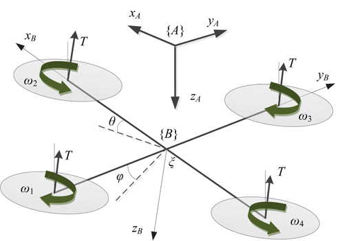
Quadrotors consist of four rotors attached to a rigid crossshaped airframe, as shown in Figure 1, with two opposing rotors rotating clockwise (1,3) and the other two rotating counterclockwise (2,4). The quadrotor is controlled by using the differential control of the thrust generated by each rotor. Vertical motion is accomplished by simultaneously increasing or decreasing the speed of all four rotors. Pitch motion is achieved by increasing the difference in the speed between the front and rear set of rotors. Roll motion is archived in the same manner using the left and right set of rotors. A quadrotor is an underactuated system, which means that the forward/backward and left/right motions are coupled with pitch and roll motions, respectively, and the quadrotor can be controlled through them. The remaining yaw motion can be realized by increasing the speed of the two rotors rotating in the clockwise direction and by decreasing the speed of the remaining two rotors.
The dynamics of quadrotor helicopters have been studied in detail by several groups [13, 14]. A rigid-body model of a quadrotor can be obtained using Newton’s equations [15], as given in Eq. (1):
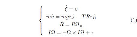
where
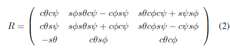
where
The total thrust and torques produced by the four rotors are denoted by

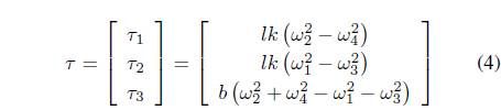
where
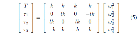
The rotor speeds required for the given values of thrust and moments can be found using Eq. (5) and the inverse of the constant matrix .
The model given in Eq. (1) is a simplified model that does not consider several aerodynamic effects such as vortex ring state, blade flapping, etc. [15]. However, it is reasonable to neglect these effects at low values of UAV speed for the sake of model simplicity.
3.1 General Control of Quadrotor
The control problem is challenging for several reasons. First, the system is underactuated: there are four inputs, whereas the workspace is six dimensional. Second, the aerodynamic model described above has been simplified. In addition, practical motor controllers must overcome the drag moments to generate the required speeds and realize the input thrust
This paper focuses on the design of a dynamic feedforward compensator incorporated into the position controller. Position control is achieved by means of conventional proportionaldifferential (PD) controllers, because low velocities are assumed.
3.2 Dynamic Feedforward Compensator Design
A quadcopter position controller can be separated into an altitude controller and a translational motion controller. In the hovering mode, only the altitude controller needs to operate; this controller is usually a PD-regulator with constant feedforward compensation for the gravity term. However, when the UAV changes the flight mode from hovering to translational motion, the performance of the altitude controller may deteriorate.
Quadrotor UAVs must change their roll and/or pitch angles to perform translational motion in the X- or Y-direction. Because the thrust provided by the propellers is always normal to the quadrotor plane, the vertical component of the thrust, which is required to maintain the altitude, can be significantly reduced as a result of quadrotor roll. This results in the UAV losing altitude, which is considered undesirable in most applications and may cause a collision between the vehicle and the environment.
As quadrotors are conventionally equipped with sensors monitoring the posture of the UAV, the values of pitch and roll angles are available to the control system. Using an accurate mathematical model, it is possible to compensate for the loss of thrust by employing a feedforward term, if the pitch and roll angles are known.
The equation for altitude dynamics can be derived as an extension of the second expression in Eq. (1).

Substituting the expression for

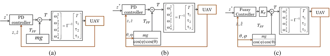
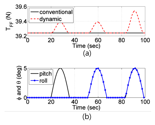
Normally, quadrotor control systems use static feedforward gravity compensators, as shown in Figure 3a. The compensation term
Therefore, we propose the use of a dynamic feedforward compensator term that will change with the roll and pitch angles according to
3.3 Design of Fuzzy Controller
To improve the performance of altitude control, the PD controller was replaced by a fuzzy logic controller. The proposed fuzzy logic controller provides a faster response with less overshoot by allowing different system parameters to exhibit their most advantageous features at different times. In the proposed fuzzy logic controller, the desired height value

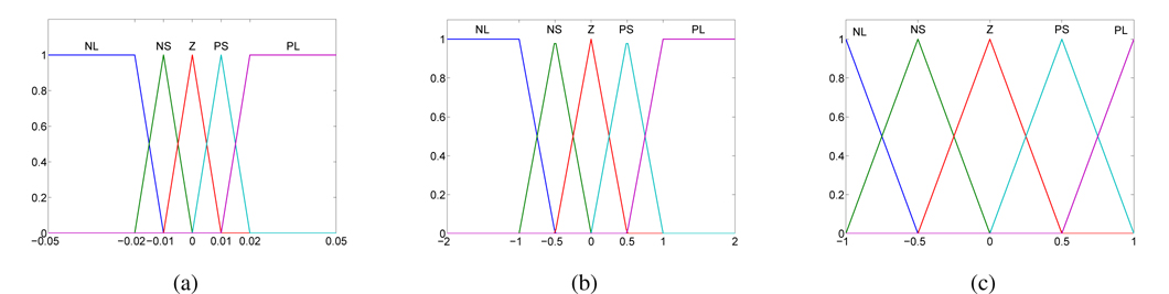
The inputs of the fuzzy controller are the position error
The fuzzy logic controller’s output indicates how much we need to add to the initial feedforward speed. The output thrust due to the height controller is calculated as need to add to the initial feedforward speed. The output thrust due to the height controller is calculated as

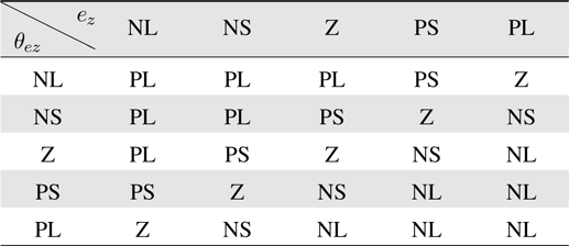
It should be noted that, in the proposed rules, “negative error” means that the value of the actual position is greater than that of the desired position. Therefore, in this case, we need to decrease the speed of all four motors so as to reduce the thrust force. On the contrary, ’positive error’ means that the value of the actual position is lower than that of the desired position; thus, the speed of the motors should be increased to create a larger thrust force. Using these restrictions, the rules of the fuzzy controller are shown in Table 1. Fuzzy inference generated using the Mamdani method is used. The method of defuzzification used is centroid.

Rule base
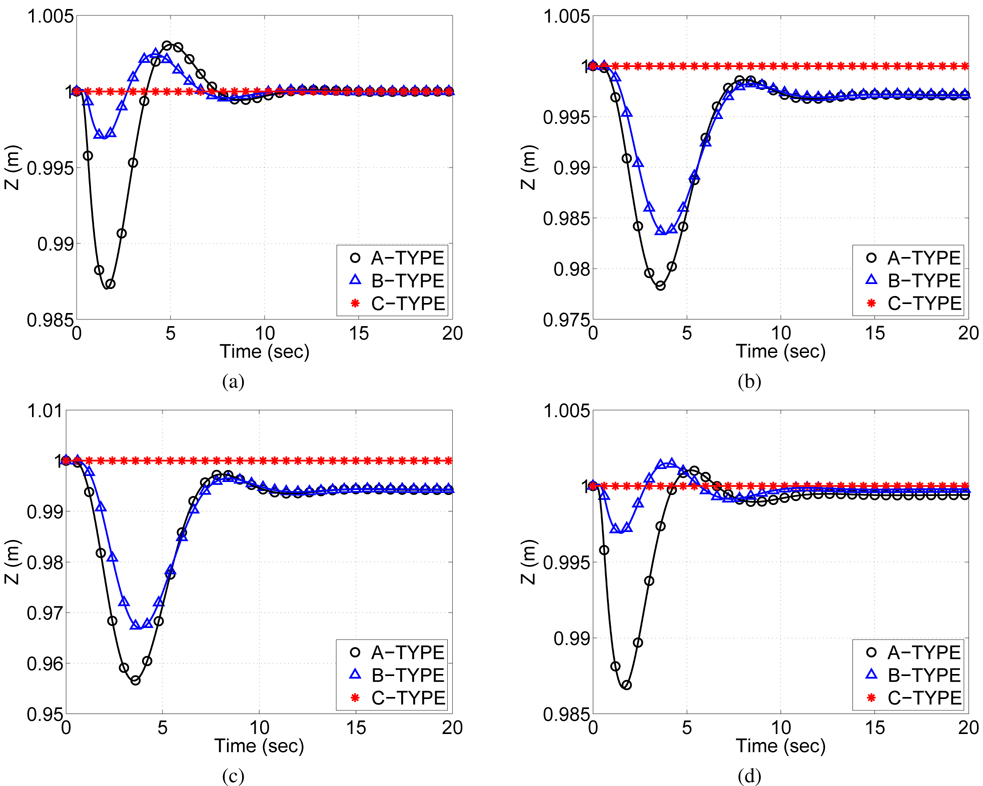
The effects of the proposed feedforward compensator and the proposed fuzzy logic controller on the UAV performance were investigated in a series of computer simulations. A MATLAB model of a quadrotor UAV was used, with the physical parameters of the quadrotor adopted from the model provided in robotics toolbox for MATLAB. In the four simulation cases, the UAV moves from its starting position (0,0,1)
to a given point along the X-axis (desired end point is (1,0,1))along the X-axis with a constant speed ( = 1 m/s)along the X- and Y-axis with a constant speed ( = 1 m/s, = 1 m/s)along a circular trajectory in the X-Y plane (x = cos 0.3t m, y = sin0.3t m).
In all simulation scenarios described above, the altitude of the UAV is required to remain constant.
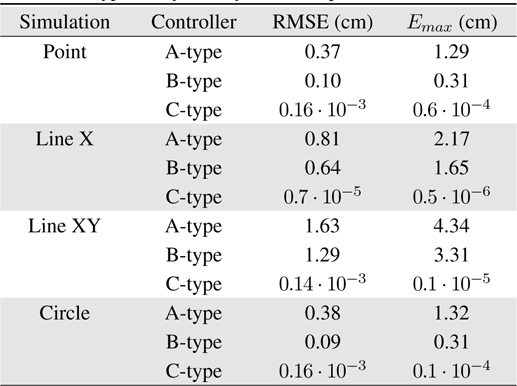
The simulation results are shown in Figure 6. In all of the simulation cases, the root-mean-square error (RMSE) and maximum error (

RMSE and maximum altitude drop (Emax) for a system with A-type (constant compensation), B-type (dynamic compensation), and C-type (fuzzy with dynamic compensation) controllers
It should be noted that the proposed feedforward controller improved the performance of the system in all simulation cases. The effect of the controller is more significant in the first and fourth scenarios, when the RMSE decreased from approximately 0.4 cm to 0.1 cm and the maximum error decreased from 1.3 cm to 0.3 cm, which corresponds to an approximately 75% reduction in the altitude drop. In the case of motion along a straight line (cases 2 and 3), implementation of the proposed controller resulted in a reduction in RMSE and maximum altitude error by approximately 21% and 24%, respectively. Implementation of the proposed fuzzy logic controller instead of the PD controller allowed further improvement in the performance of the system in all simulation cases. The effect of height drop is nearly canceled in all four scenarios as a result of the implementation of the proposed fuzzy logic controller. In addition, the RMSE decreased by a factor of 100, and the maximum error decreased by a factor of 104.
5. Conclusions and Future Work
In this paper, we proposed a dynamic feedforward compensator for altitude control of quadrotor UAVs. The main concept was to incorporate pitch and roll measurements into the feedforward term of the altitude controller so as to provide a higher thrust force when the UAV flight mode changed from hovering to translational motion in the horizontal plane. To further improve altitude control of the quadrotor UAV, we proposed a fuzzy logic based controller that was designed using expert knowledge and was more flexible than a PD controller. A series of numerical simulations were performed to analyze the performance of both controllers; they showed that the implementation of the proposed controllers led to improved results.
Future work will consider improvements to the proposed controller. Additionally, we intend to investigate the performance of the proposed algorithm in a hardware implementation. Conflict of Interest No potential conflict of interest relevant to this article was reported.
No potential conflict of interest relevant to this article was reported.