본 논문은 태양광 혹은 인공광이 존재하는 외부 환경에서 광필터를 적용한 실험적 실외 광무선 데이터 통신 시스템을 제안한다. 광잡음의 효과적인 차단을 위해 마이크로루버 필름을 사용한 광필터를 광다이오드에 직접 적용하였으며 잡음광이 광다이오드에 정면으로 입사하지 않는다는 가정하에 입사각 30도를 초과하는 잡음광을 차단하도록 설계하였다. 제안하는 시스템을 낮시간 실외에서 데이터 전송을 통해 검증하였는데 지정한 입사각 혹은 그 이상의 입사 잡음광에 대해 거의 완벽하게 차단할 수 있었으며 전송된 패킷데이터의 90%이상을 성공적으로 수신하였다. 본 제안 시스템은 향후 실외 자유공간 광무선 데이터 전송에 효과적으로 사용될 수 있을 것이다.
Visible light communications (VLC) use LEDs to transmit data using intensity modulation (IM) techniques. The intensity level detected at the receiver is converted into an electrical signal, thus being termed as direct detection (DD). These IM/DD methods are popular in VLC because they are relatively simple and also easy to implement. Visible light communication (VLC) is favorably considered in many applications, such as high-speed wireless data communications, intelligent transportation systems, etc. [1, 2]. The VLC systems can also be found attractive in many outdoor applications, such as vehicle safety functions and WPANs. However, for the outdoor applications, the VLC suffers from strong influence of ambient light noise. The majority of existing studies related to VLC has been focused on indoor environments [3]. A few reports have attempted to address the outdoor applications. Recently, Lourenco et al. [4] have demonstrated that the outdoor VLC in the presence of significant optical noise levels can be achieved using direct sequence spread spectrum. Lee et al. [5] have proposed an analytical model in the presence of daylight together with the selective combining technique.
Daylight is essentially an unmodulated source with average power much larger than the desired signal. Therefore, the effect of these ambient noise lights is so significant that the performance of outdoor optical wireless data communication systems can be highly susceptible. In view of this adverse effect from ambient-light noise, an outdoor optical wireless data communication needs to be investigated, while efficiently blocking or reducing the noise light for outdoor VLC data transmission.
This paper experimentally investigates an outdoor optical wireless communication system with an efficient optical filter in the presence of sunlight or any other artificial light.
In Section II, we describe the outdoor VLC system with optical filters. The experimental results from the proposed system are followed in Section III. Conclusions have been drawn in Section IV.
Ⅱ. Outdoor VLC System with Optical Filters
2.1. Measurements of Light Intensity
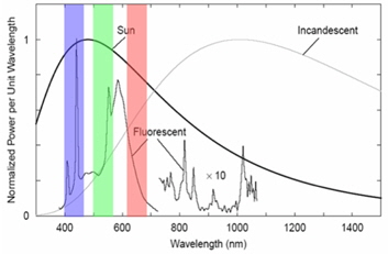
For visible light communications, we note that there exist various light noises as seen in Fig. 1.
In order to evaluate the effect of ambient light noises, we first conducted a measurement of light intensity in various indoor/outdoor environments.
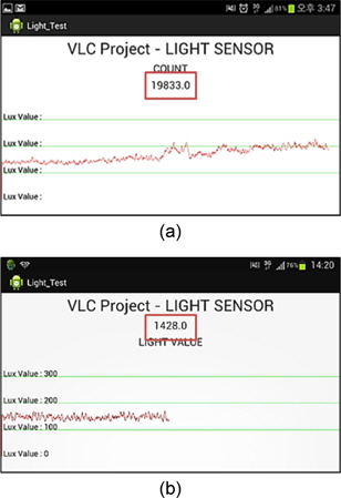
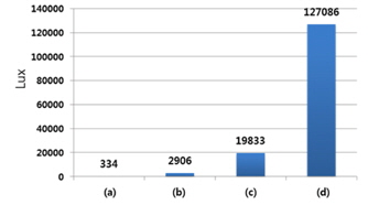
For easiness of light intensity measurement, we have developed an Android application on Jellybean 4.1.2 platform using Google Android SDK [6]. This application converts the light intensity measured through the light sensor into corresponding values in lux. Using this application, we have performed an experiment to measure the light intensity in indoor, outdoor-shaded, outdoor-obliquely incident (10° ≤ θ ≤ 30°) sunlight and outdoor-directly incident sunlight. 2 shows the light intensities of these four conditions. It can be seen that even when measured in the shaded outdoor environment, the intensity is approximately 9 times higher than in indoor environments. On the other hand, when measured outdoors, the signal becomes saturated, therefore being unable to detect the signals. That is, it is impossible to convey any symbols over VLC in an outdoor environment, unless specific compensation or avoidance methods are employed.
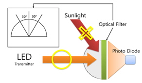
Following the analysis of the effect of light noise and the assumption that the VLC link does not establish on direct sunlight, we design the outdoor VLC data system to block obliquely incident lights via optical filtering. Furthermore, we aim to achieve similar intensities to indoor or outdoor-shaded by applying an optical filter. That is, the optical filter is designed to block unwanted light noise so that a desirable outdoor VLC environment would be made as if it were in indoor or outdoor-shaded environments. Fig. 3 illustrates the main principle of the optical filtering in outdoor environments.
2.2. Outdoor VLC with Optical Filters
For an efficient VLC data communication system, we first design an optical filter to block any artificial light or light noise for a VLC link outdoors. To this end, we have designed a light sensor module for receiving the LED light and subsequent data analysis. This module obviously includes a photo diode and consists of collimate lens on the top of the photo diode for the purpose of focusing incident light onto the photo diode. The optical filter is laid on this lens for blocking unwanted lights.
Within the module, we choose TSL252R as a light sensor. It is known that this light sensor passes up to 80% of input value for any lights incident between 0 and 30° [7]. It also responds well to the wavelength between 700 and 800nm. It is apparent that output voltage is directly proportional to the light intensity (irradiance) on the photodiode. The optical filter we employed is one of light control films that contain a special layer called microlouver [8]. One of the most important advantages of this film is that by varying the thickness and angle of the microlouver, the desired blocking performance can be achieved. For the current experiments, the louver angle is adjusted to 30°.
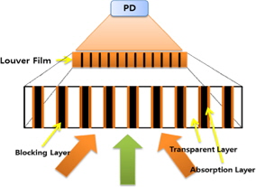
Fig. 4 shows the blocking effect of the filter in detail. The louver film consists of transparent layer, absorption layer and blocking layer. The film is designed such that the light incident from within the specified angle passes through via the transparent layer, whereas the light beyond that angle is first absorbed and eventually blocked via the absorption and the blocking layers. Therefore, the light incident within the specified angle impinges upon the light sensor.
2.3. Outdoor Visible Light Data Communication
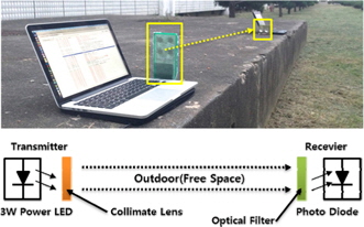
Following the purposely designed optical filter, we have built an experimental VLC data communication system. Fig.5 shows the experimental system.
The LED transmitter consists of a microcontroller unit (MCU) called Arduino UNO R3 [9] operating at 16MHz clock speed. A 3W white LED driven by 5V has been employed. It must be noted that this LED is popular for illumination as well as communication. For the convenience and flexibility of data analysis, we have used an Android device with dual-core Exynos based GT-N7000 [10] and the photo diode embedded in the Android device.
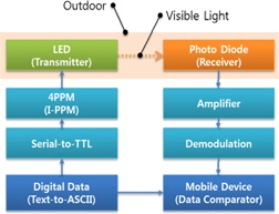
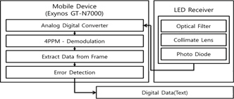
As mentioned previously, the experiment was conducted with the optical filter attached in outdoor environments. By varying the distance between the transmitter and receiver, the received data were recorded. The block diagram of the system is shown in Fig. 6.
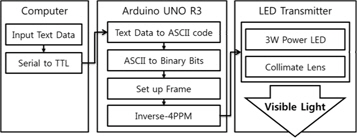
The transmitter is composed of three main parts: data conversion via computer, LED driver and LEDs. When the user data is received, the data is first sent to the controller via serial communications. The controller then converts the data (text) into binary data via ASCII codes. Then, this data is formed as a data frame. To drive a LED, inverse 4PPM modulation has been employed and the 3W Power LED transmits over free space. The collimate lens around the LED make the light focused. Fig.7 shows the block diagram of the transmitter.
The details of the receiver are described below.
The light transmitted first impinges upon the optical filter that would block unwanted light or other ambient light noise. Then, the light will pass through to the photo diode. The analog-to-digital converter is employed to convert back into the digital data. At this point, demodulation is performed to extract the data frame. The parity bit is evaluated for frame error occurrence. If the frame is in error, that frame is discarded, otherwise the data is extracted. As mentioned earlier, the data extraction is conducted using the Android device. The detailed operation of the receiver is shown in Fig.8.
2.3.3. Data Frame and Modulation
Data is framed as shown in Fig.9. The start of the frame is indicated by SOF, whereas EOF is used to signal the end of the frame. These two overhead are 16bits, while the payload occupies 16bits.
The SOF of 8bits includes PRE field that is essentially 8bits of alternating “1” and “0” and used to synchronize the data. For the detection of error occurrence, the even parity bit is included in the EOF field. Therefore, the frame size is 32bits.
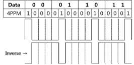
The modulation for the VLC transmission is the inverse 4PPM scheme. This scheme is shown in Fig.10. Although the PPM scheme can also be used, the inverse PPM is employed because of the illumination of LEDs. That is, the logic 0 state is regarded as pulse on state and the logic 1 state is pulse off state.
2.3.4. Data Frame and Modulation
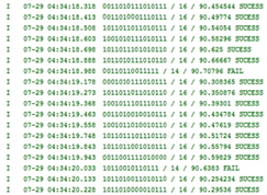
Fig.11 shows the received data extracted the frame. In other words, by removing the SOF and EOF, the data are recovered and frame error rate (or bit error rate) is computed.
Prior to the data transmission in the proposed VLC data system, we have first conducted the evaluation of the optical filtering. The experiment was conducted in broad daylight approximately at 2:00 p.m. on the campus. The distance between the transmitter and receiver is approximately 2m. We have compared light intensity before and after the optical filtering. It is shown in Fig.12 that the sunlight has been significantly reduced with the optical filter made of the microlouver film in terms of light intensity. Only 7.2 percentage point of the light was detected with the optical filter. This result verifies the effectiveness and significance of the optical filtering.
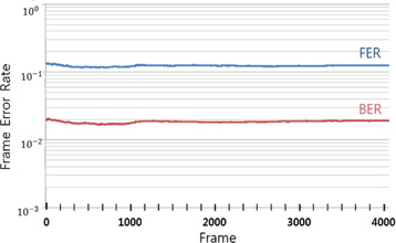
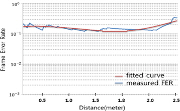
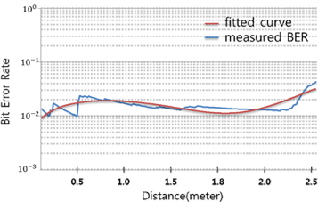
With this filter attached, we continued to experiment the proposed VLC data communication. By keeping approximately 1.5m between two points, 3,904 frames equivalent of 124,928bits are transmitted. The frame and bit error rates are measured and shown in Fig. 13. Further to the above measurements, it would be interesting to observe performance variation according to the distance between the transmitter and receiver. For this measurement, we measured the performance from 0m to 2.5m in terms of distance. Fig.14 and Fig.15 are shown the frame and bit error rates, respectively.
The bit error rates over distance appear to be nearly constant, although the measurements over a relatively short distance show slightly higher error rates. In other words, the error rates are approximately between 1% and 2% for a given number of frames transmitted. Therefore, the outdoor VLC transmission over a given distance can be said to be successful. The curve fitting for the bit error rate has been conducted and is found below.
where
It is important to note that the frame and bit error rates alike increase sharply at a distance of approximately 2.5m. This finding indicates that the VLC data transmission is reliable up to a certain distance, although the optical filter is employed, beyond which the LED intensity is not sufficiently strong to convey any data and thus light noise becomes dominant, thereby causing significant transmission errors.
It should be noted that due to the fact that relatively low-power LED (3W) with 9V/1A supply is employed, the distance we have achieved is approximately 2.5m. Also, for the same reasons, FER and BER are shown to be somewhat limited to 10-1 and 10-2, respectively. This power LED is applied usually for illumination as well as communication. However, the distance can be further increased and also the performance can be enhanced with more sophisticated and high power driven LEDs. We note that a laser LED (or laser diode [11]), which is more suited to communication rather than illumination, can be applied to extend the distance as the laser diode produces coherent radiation in which the waves are all at the same frequency and phase in the visible spectrum.
An experimental visible light data communication system has been presented. Based on the unique optical filter made of microlouver film, the proposed system is able to convey data over a certain distance. Thus, the experimental system combined with the optical filter offers a reliable and efficient outdoor VLC transmission. The VLC data link, however, shows a degree of vulnerability as the distance increases. This is due to the fact that the data-bearing intensity becomes weaker as the receiver moves away. An extended distance for the outdoor VLC data communication would be obtained with more advanced LEDs, such as laser diode. Even so, the proposed system manifests itself in presenting the viability of future outdoor free space VLC networks using already established infrastructure.