본 논문은 능동카메라가 장착된 이동로봇의 장애물 회피를 위한 퍼지추론방법 제시하였다. 영상센서를 이용하여 상황적 판단에 근거한 명령융합을 사용하여 미지의 환경에서의 목적지까지의 지능적인 탐색을 수행하도록 하였다. 본 연구를 검증하기 위하여 환경모델과 센서데이터에 기반 한 이동로봇의 경로생성을 위한 물리적 센서융합을 시도하지 않고, 환경에 따른 각각의 로봇의 주행행동을 제어하기 위한 명령융합 적용하였다. 주행을 위한 전략으로는 목적지 접근과 장애물 회피를 수행할 수 있도록 퍼지규칙 조합을 통해 판단하도록 수행하였다. 제안한 방법을 검증하기 위하여 영상데이터를 사용한 성공적인 주행 실험 결과를 제시하였다.
Autonomous mobile robot is intelligent robot that performs a given work with sensors by identifying the surrounded environment and reacts on the state of condition by itself instead of human. Unlike general manipulator in a fixed working environment [1], it is required intelligent processing in a flexible and variable working environment. And studies on a fuzzy-rule based control are attractive in the field of autonomous mobile robot. Robust behavior in autonomous robots requires that uncertainty be accommodated by the robot control system. Fuzzy logic is particularly well suited for implementing such controllers due to its capabilities of inference and approximate reasoning under uncertainty [2].
This requires formulation of a large and complex set of fuzzy rules. In this situation a potential limitation to the utility of the monolithic fuzzy controller becomes apparent. Since the size of complete monolithic rule bases increases exponentially with the number of input variables [2, 3], multi-input systems can potentially suffer degradations in real-time response. This is a critical issue for mobile robots operating in dynamic surroundings. Hierarchical rule structures can be employed to overcome this limitation by reducing the rate of increase to linear [4].
First, this paper briefly introduces the operation of each command and the fuzzy controller for navigation system in chapter 2. Chapter 3 explains about behavior hierarchy based on fuzzy logic. In chapter 4, experimental results to verify efficiency of system are shown. Finally, Section 5 concludes this research work and mentions possible future related work.
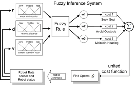
The proposed fuzzy controller is shown as follows. We define three major navigation goals, i.e., target orientation, obstacle avoidance and rotation movement; represent each goal as a cost function. Note that the fusion process has a structure of forming a cost function by combining several cost functions using weights. In this fusion process, we infer each weight of command by the fuzzy algorithm that is a typical artificial intelligent scheme. With the proposed method, the mobile robot navigates intelligently by varying the weights depending on the environment, and selects a final command to keep the minimum variation of the cost function [5, 6].
Seeking Goal command of mobile robot is generated as the nearest direction to the target point. The command is defined as the distance to the target point when the robot moves present with the orientation, 𝜃, the velocity,
where,
Avoiding obstacle command is represented as the shortest distance to an obstacle based upon the sensor data in the form of histogram. The distance information is represented as a form of second order energy, and represented as a cost function by inspecting it about all 𝜃 as shown in Eq. (2).
To navigate in a dynamic environment to the goal, the mobile robot should recognize the dynamic variation and react to it.
Maintain heading command is minimizing rotational movement aims to rotate wheels smoothly by restraining the rapid motion. The cost function is defined as minimum at the present orientation and is defined as a second order function in terms of the rotation angle, 𝜃 as Eq. (3).
The command represented as the cost function has three different goals to be satisfied at the same time. Each goal differently contributes to the command by a different weight, as shown in Eq. (4).
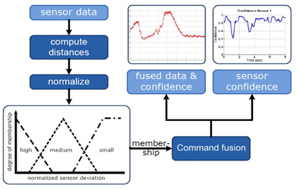
We infer the weights of the usual fuzzy if-then rule by means of fuzzy algorithm. The main reason of using fuzzy algorithm is that it is easy to reflect the human's intelligence into the robot control. Fuzzy inference system is developed through the process of setting each situation, developing fuzzy logic with proper weights, and calculating weights for the commands [6, 7].
Fig. 2 shows the structure of a fuzzy inference system. We define the circumstance and state of a mobile robot as the inputs of fuzzy inference system, and infer the weights of cost functions. The inferred weights determine a cost function to direct the robot and decide the velocity of rotation. For the navigation control of the mobile robot, the results are transformed into the variation of orientation and angular velocities by the inverse kinematics of the robot .
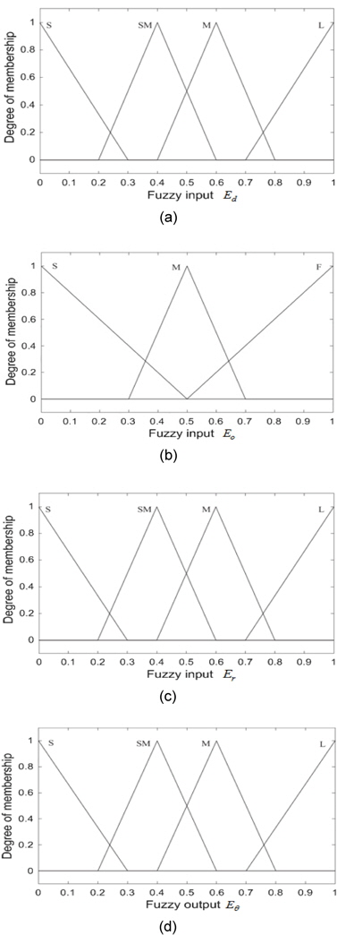
Fig. 3 shows the output surface of the fuzzy inference system for each weight fuzzy subsets using the inputs and the output. The control surface is fuzzy logic controller of seeing goal (a), fuzzy logic controller of avoiding obstacle (b), fuzzy logic controller of minimizing rotation (c), and fuzzy output (d).
A mobile robot moves by selecting a more secure path after recognizing the environment to navigate using image information. When we estimate the environments from the conditions of camera’s actuator[4, 8], there are many uncertainties. That is, environment informations estimated from the errors of camera angle 𝛼, 𝛽, link parameters
where Δ
Image information
Uncertainty of images, therefore, represented that of real distance information X, Y. PDF which presented uncertainty of X, Y about a transformation of Eq. 7 is given by
Where
and |
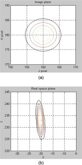
Fig. 4 shows the simulation results about uncertainties between image plane and real space plane on condition that 𝛼=15°, 𝛽=0°, j=160 and k=180. The longer X, Y image distance, PDF of x, y is lower. It meant that long distance information has lower trust.
This navigation method that includes the proposed algorithm is applied for mobile robot named as
This modified
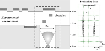
With the proposed method, we make an experiment on building environmental map. Parameter values used for experiment are shown in Table 1.
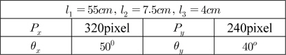
실험에 대한 파라미터 값
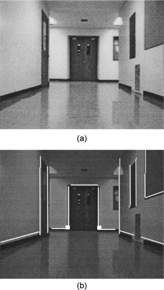
Fig. 6(a) is the image used on the experiment; Width of corridor is 2m and Joint angle parameter α, β of active camera are 11° and 0° respectively. After capturing the image, The ‘LOG’ operator is utilized to extract the edge elements. It is suitable for detecting edge element at corridor that appear noises (e.g.: Patterns of the bottom, wall) sensitively because it is difficult for edge detection in case of other edge operators which has the characteristic of high-pass filter.
The essential information to map building is edge information that meets with the bottom in the edge information extracted from LOG operation. Fig. 6(b) shows the image that the points meet with the bottom through the matching after LOG operation. We construct probability map by this informations [10].
Fig. 7(a) shows the map including the experimental environment. We exclude the information over 6m because that has low probability. Because we can estimate the reliability through the probability approach, the better map can be acquired.
Fig. 7(b) is the values resulted from matching after image processing which shows the estimated map over front 6m. The brightness presents the probability, and through the transformation, in case of having the area of the same distance in the image, the farther the point is, the smaller the probability is. Therefore the information which extracted image has low truth because it has wide probability density.
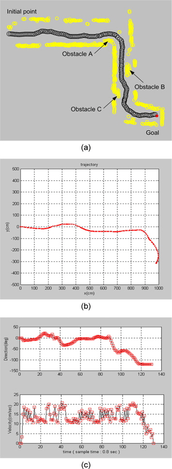
Fig. 7(b) shows that maximum matching error is within 4% of the dash-line area in Fig 7(a). Therefore, it can be seen that above vision system is proper to apply to navigation. The mobile robot navigates along a corridor with 2m widths and without obstacles and with some obstacles, respectively, as shown in Fig. 8. The real trace of the mobile robot is shown in Fig. 8(a).
Fig. 8 illustrates the navigation–obstacle avoidance strategy by proposed method. The experimental results exhibit that the mobile robot can start moving from an initial point, avoids the box-like obstacles, and reaches a goal point. Fig. 8(a) shows the case study of three obstacles. Based on the evaluation qualitative method of the obstacles configuration from the information of the vision sensor, the mobile robot succeeds to reach the goal point in an environment cluttered with obstacles.
It demonstrates that the mobile robot avoids the obstacles intelligently and follows the corridor to the goal. In Fig. 8(b) the mobile robot performs a wall following mission in a narrow dead-end corridor. In the extreme situation at the end of the corridor accurate control response is required to avoid collision. When approaching the two corners corridor, the frontal vision sensors detect the wall, doors and the mobile robot performs a fast right turn and left turn, respectively. The robot’s velocity is reduced accordingly (see Fig. 8(c)).
Finally, it should be pointed out that command fusion based fuzzy inference prove to be a satisfactory control strategy and has shown a good degree of robustness face to a large variability and uncertainty in the parameters. Overall, this project this project has served as a platform of a whole work dealing with mobile manipulation, where separation of tasks is considered.
A fuzzy control algorithm for both obstacle avoidance and path planning has been implemented in experiment so that it enables the mobile robot to reach to goal point under the unknown environments safely and autonomously.
First, a theoretical development of a navigation procedure of a mobile robot with active camera in unknown environment with obstacle has been described.
Second, we showed an architecture for intelligent navigation of mobile robot which determine robot's behavior by arbitrating distributed control commands, seek goal, avoid obstacles, and maintain heading. Commands are arbitrated by endowing with weight value and combining them, and weight values are given by fuzzy inference method. Arbitrating command allows multiple goals and constraints to be considered simultaneously. To show the efficiency of proposed method, real experiments are performed.
To show the efficiency of proposed method, real experiments are performed. The experimental results show that the mobile robot can navigate to the goal point safely under unknown environments and also can avoid moving obstacles autonomously.