CB Center of buoyancy CG Center of gravity FOWT Floating offshore wind turbine MSL Mean sea level RAO Response amplitude operator RNA Rotor nacelle assembly STL Spring tensioned leg TLP Tension leg platform UOU University of Ulsan
Recently, some floating offshore wind turbines (FOWT) have been developed and deployed in deep sea, while a large number of offshore wind turbines with fixed foundations have been installed in water depths less than 50
Several researches on FOWT have been made. Bulder et al. (2002) analyzed a tri-floater platform wind turbine; Lee (2005) studied a 1.5-
To produce electricity with higher efficiency at lower costs in deep sea, however, it is necessary to consider building wind farms with plenty of FOWTs, not a single FOWT. Then, FOWTs should require not only smaller foot prints to prevent mutual interferences among them, but also installation cost lower than those of existing FOWTs.
In this paper, a new substructure of FOWT satisfying both smaller foot prints and lower installation costs in 50
Model tests with a 1/128 scale ratio were carried out in the Ocean Engineering Wide Tank of UOU to predict the characteristics of motions of the FOWT platform in wind and waves. Comparisons are made between the inverted conical cylinder in 50
>
Floating offshore wind turbine model
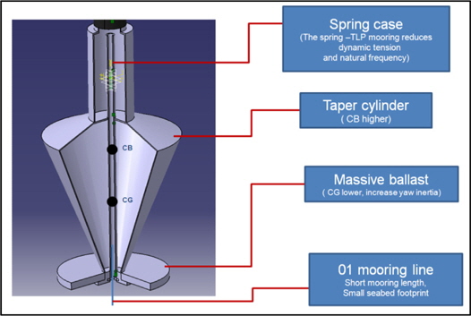
Based on the OC3-Hywind moored by a STL in 320
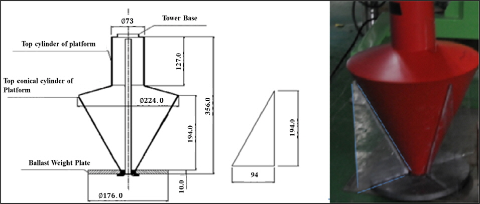
Fig. 2 illuminates its detailed drawing with a spring case inside. Principal particulars of the floating offshore wind turbine are given in Table 1.
[Table 1.] Principal particulars of FOWT.
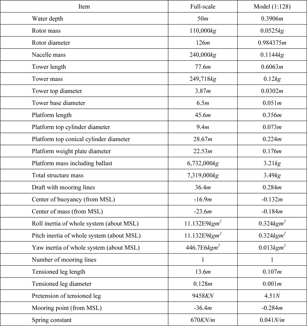
Principal particulars of FOWT.
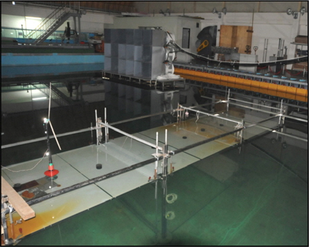
The model tests were performed in the Ocean Engineering Wide Tank, UOU (L × B × D × Dw = 30
Four passive makers were mounted on the tower of the model in Fig.1 to measure motions in six degrees of freedom by eight VICON cameras (Fig. 3). Before the model test, wind speed was measured by 12 anemometers at the position where the model would be installed. The wind generator produces mean wind speeds up to 10
The principal dimensions are shown in Fig. 4. Four triangle plates, which are made of light plastic material, were attached to the platform for reducing surge and pitch motions of the platform. These plates were used to get large drag forces at lower part of platform.
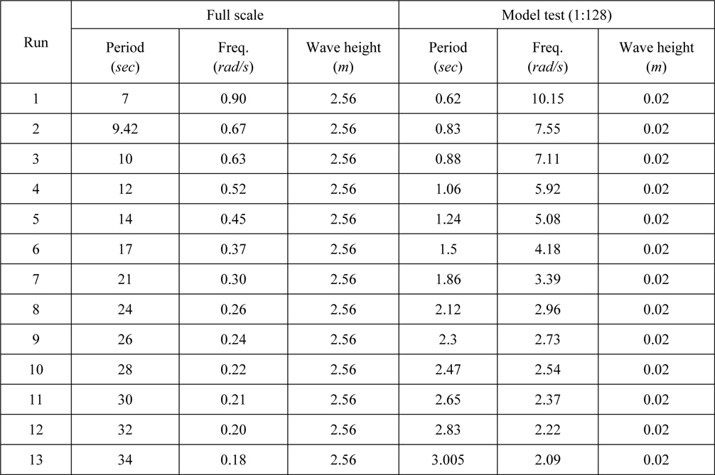
The model test was carried out in regular and irregular waves without/with wind and rotating rotor to obtain the response amplitude operator (RAO). Wave generator produces 13 regular waves and 4 irregular waves as shown in Tables 2 and 3. An electricity motor is used for driving the rotor. In this test, wind speed and rotor speed are based on the rate wind speed of the NREL 5-
Rotor speed of scale model = 136.9rpm Mean wind speed of scale model = 1.007m/s Two load cases are defined as follow: LC1: Regular waves, no wind, parked rotor LC2: Regular waves, mean wind speed and rotating rotor
[Table 2.] Regular waves for LC1 and LC2.

Regular waves for LC1 and LC2.
[Table 3.] Irregular wave conditions for LC3 and LC4.
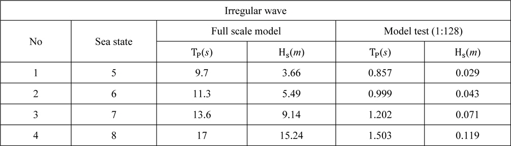
Irregular wave conditions for LC3 and LC4.
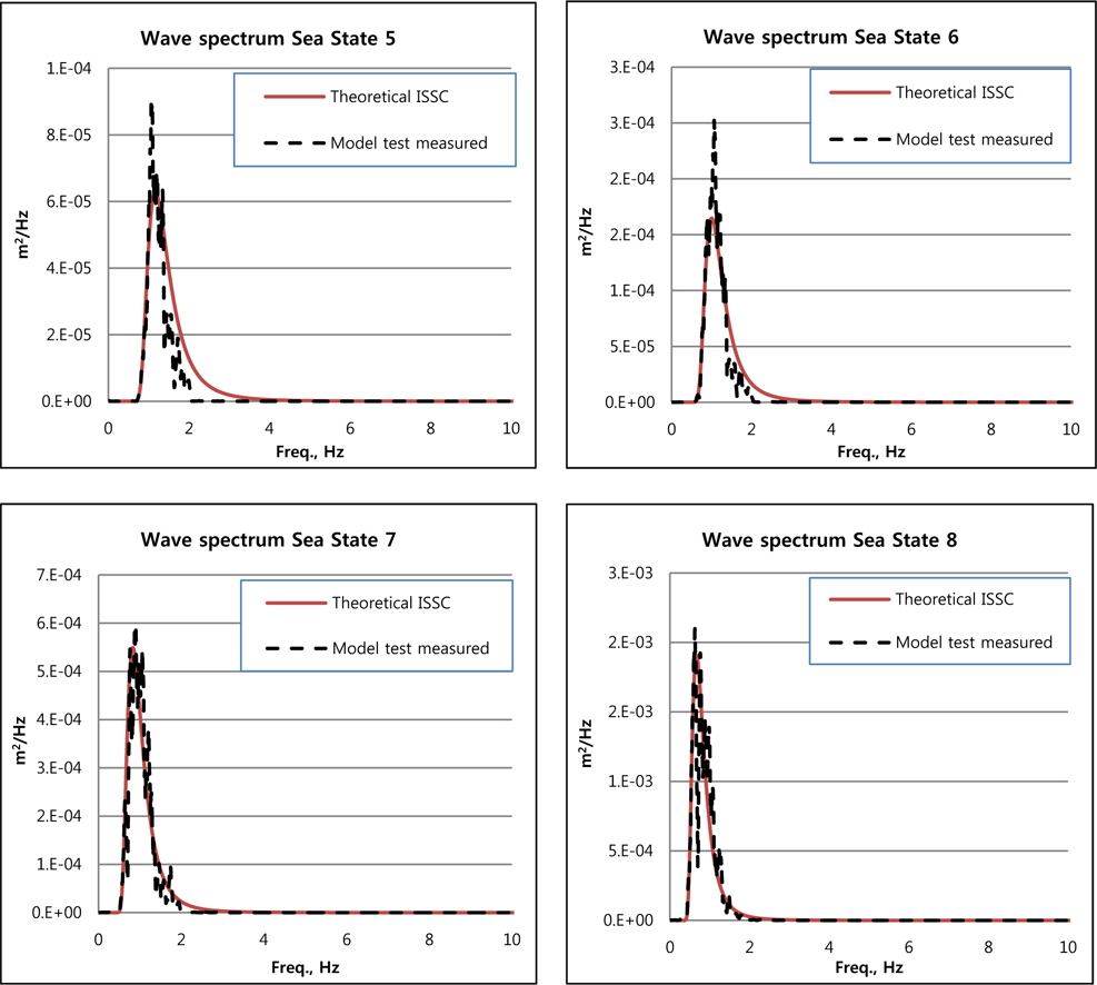
ISSC wave spectrum was applied to 4 irregular waves as in Table 3. Based on these waves, 2 load cases were defined as follows: LC3: Irregular waves, no wind, parked rotor LC4: Irregular waves, mean wind speed, rotating rotor
Where, Hs is significant wave height and Tp is peak-spectral wave period.
These irregular waves were produced during 256
>
RAO (Response Amplitude Operator)
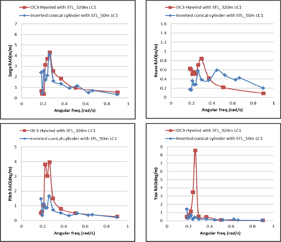
Fig. 6 shows the RAOs obtained from model tests of the OC3-Hywind moored by a long STL in 320
LC2 includes both wind and wave conditions. The scaling law for aerodynamic loads of FOWT has not been established and still be in dispute for application in basin model test. Froude scaling in this model test was applied to produce wind speed and the rotor-thrust might be underestimated. Both thrust and torque can be representative of those in full scale with both wind speeds and blade pitch angles controlled properly (Martin, 2011).
Due to wind and a rotating rotor, the platform drifts to a new equilibrium position and oscillates around the new position. As can be seen in Fig. 7, the inverted conical cylinder is drifted around 30
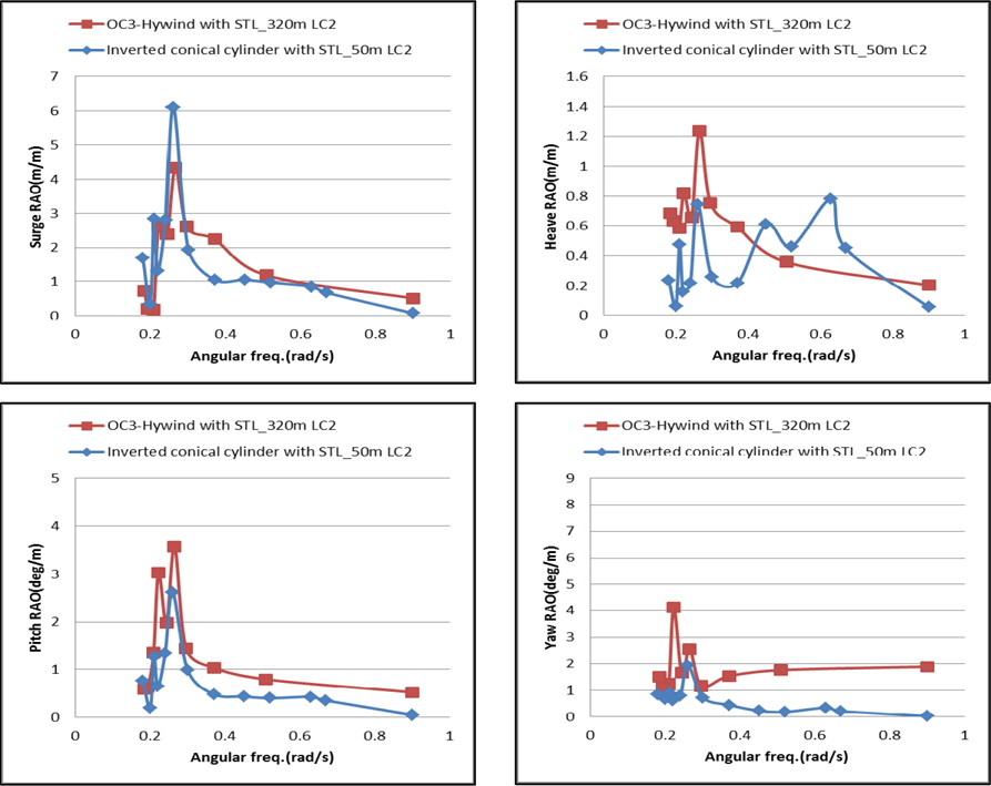
Fig. 8 presents the RAOs of two models in regular waves, mean wind speed and rotating rotor. Responses of the inverted conical cylinder moored by a short STL at 50
>
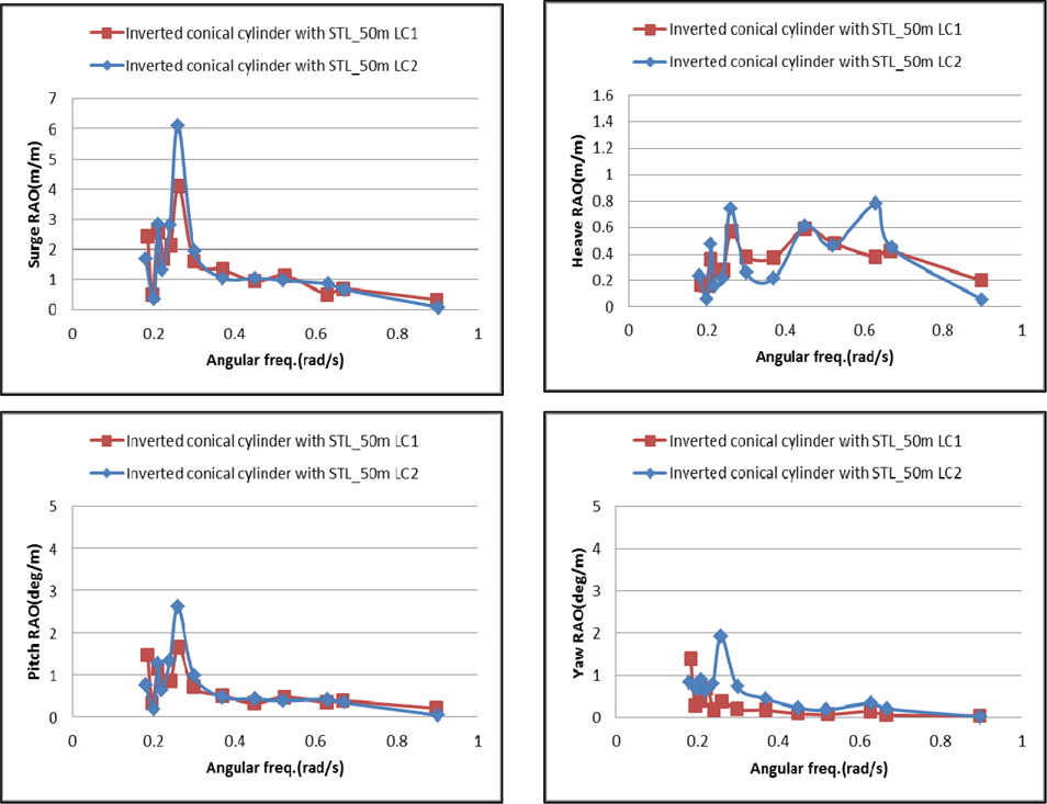
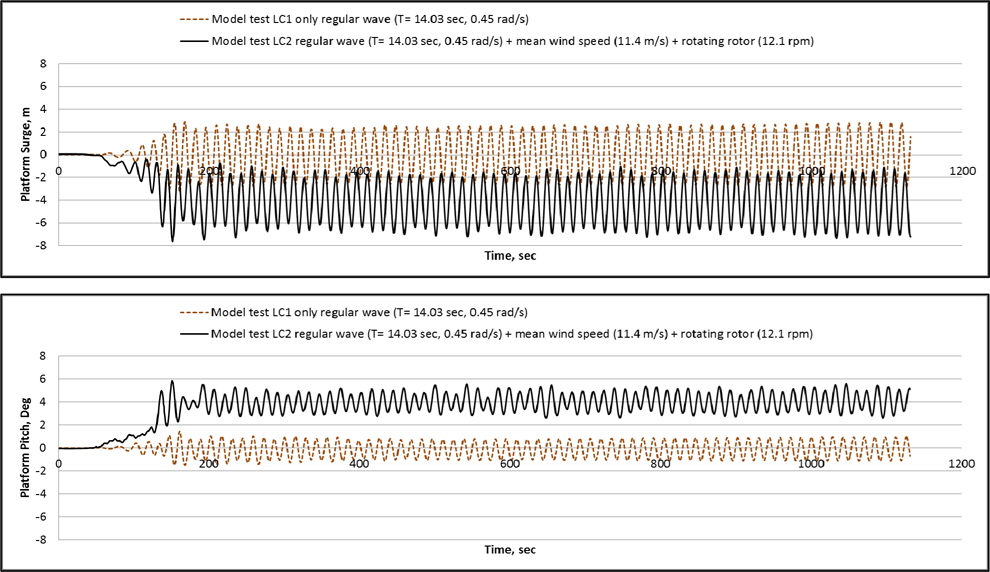
Comparison between LC1 and LC2
Fig. 9 shows comparison results between RAOs in LC1 and LC2. From that comparison, RAOs in LC1 and LC2 are similar in most of frequencies. But, RAOs in LC2 are higher than those in LC1 near natural frequencies. This phenomenon is caused by that damping near natural frequency are not adequately applied in model test. To verify this phenomenon, another model test with higher scale ratio should be performed.
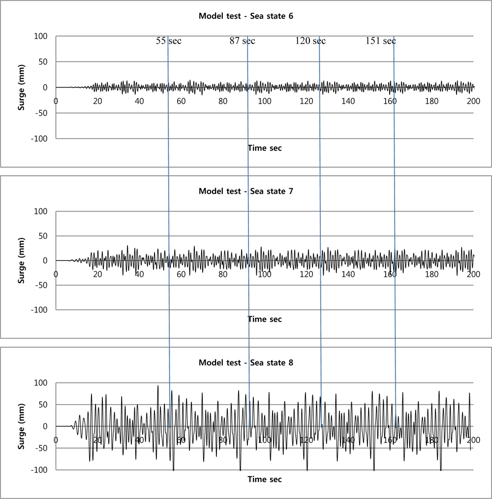
The behavior of offshore structures in irregular waves may be described in terms of significant amplitude of motion responses at specified sea states. In order to predict the significant amplitude of motion responses of the floating offshore wind Turbine, model tests were carried out in irregular waves (sea states 5~8). As shown in Fig. 10, from the captured motion response, the motion spectra were obtained and their significant heights were calculated.
There is a small static drift motion in irregular waves because of the second-order drift force. The maximum static drift motion is shown in sea state 8 as shown in Table 4 and Fig. 11.
[Table 4.] Static drift motion of 1:128 scale model in LC3 - only irregular waves.
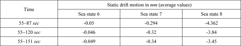
Static drift motion of 1:128 scale model in LC3 - only irregular waves.
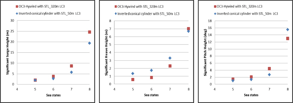
Fig. 12 shows the significant motion height of the inverted conical cylinder moored by a short STL in 50
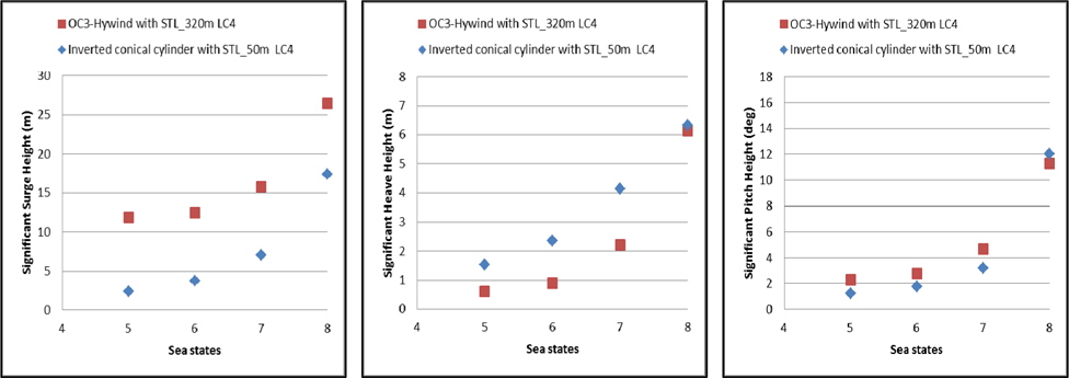
Fig. 13 shows the significant motion height of the inverted conical cylinder moored by a short STL in 50
A novel concept of FOWTs, the inverted conical cylinder moored by a STL at 50
Having the small responses and the small footprint, the inverted conical cylinder platform was designed with the ballast weight bottom plate for both low CG and large yaw inertia, the inverted conical cylinder for high CB, the STL with a spring case for both small dynamic tensions and the shift in natural frequency, and four triangle plates for small surge and pitch responses.
An inverted conical cylinder type FOWT shows decent motions in most of load cases compared with the OC3-Hywind spar model moored by a STL at 320
The inverted conical cylinder drifts in a new equilibrium position due to wind and/or a second order wave effect and oscillates around the new position. The thrust in basin model test was scaled in Froude number and may not be comparable to the one in full scale. In near future works, Reynolds number effects on the Froude scale FOWT should be clarified.
In both real sites and model basins, a torque-balanced laying construction for STL is needed to secure large yaw restoring moments as well as yaw controlling devices.