As the public communication network expands rapidly, there have been strong demands for secure personal communication. However, significant personal information is threatened to leak because of weaknesses of security systems. For this reason, information security of the public network has become a great issue. In an attempt to protect information from hacking or cracking, a number of electronic or optical cryptosystems have been proposed. One of the simple methods to ensure security is to consider all data as binary strings and to encrypt them using encryption algorithms such as DES (Data Encryption Standard) or AES(Advanced Encryption Standard) [1]. Encryption is the process of transforming a plain text to a cipher text with a security key. In order for an authorized user to decrypt the cipher text, the same correct security key has to be known to the authorized user. In conventional symmetric key cryptography, a public key is constructed previously and opened to all the users as a common key. Therefore, this type of algorithm has a weak point against data interception by an unauthorized user. Since the security key is the core of most data cryptosystems, the protection of the security key is also very important. An advanced algorithm such as 3DES or asymmetric key cryptography uses double key encryption to enhance security strength, but the sharing of the private key is needed. In general, the conventional electronic encryption methods treat binary data. However, these methods involve large amounts of computation and are not fast enough for massive-volume data [2]. On the contrary an optical processing system has the advantage of fast processing 2-D data in parallel, which makes optical systems suitable for massive data encryption. In recent years, there has been increasing interest in the use of optical encryption methods for security systems because optical systems have the merits of parallel processing and fast operation [3-12]. In each case the encrypted data is fully complex, and thus holographic recording may be required. This requirement makes it difficult to store and transmit the cipher data over digital communication networks. In order to solve this problem, optical encryption and decryption to record and reconstruct the complex values has been performed using a phase-shifting digital holographic technique [13-19]. Optoelectronic methods using digital logics are adequate for encryption. Some researchers reported XOR-based optical encryptions [20, 21].
In this paper, we propose a new optical implementation of a 3DES algorithm based on dual XOR logic operations for a cryptographic system, and show the performance of the proposed cryptosystem. The decryption can be carried out optically by using the same optical schematic. Section II is organized as four parts. In the first part, the conventional DES algorithm is overviewed. The second part explains the 3DES algorithm, and double encryption using two keys is described using XOR logic operation, in particular double encryption using private key exchanging is proposed and described. In the third part, a free-space interconnected optical logic gate method is introduced to implement the optical XOR logic operation. In the fourth part, we propose an optical architecture of 3DES and explain the encryption/decryption procedure in the proposed architecture. Computer experiments show results of the encryption and the decryption with the proposed method in Section III. Finally, conclusions are briefly summarized in Section IV.
The Data Encryption Standard (DES) which is also known as the Data Encryption Algorithm (DEA) was the first symmetric block cipher chosen and was first issued as a standard in 1977 by the American National Standard Institute (ANSI), and the National Institute of Standards and Technology(NIST) believes that DES provides adequate security for its intended unclassified information applications [1]. The algorithm specified in the DES is very complex. It encrypts plain text data in 64-bit blocks by using a 56-bit secret key. DES has been one of the most successful and widely used secret key cryptographic systems. However, some cryptographers have been arguing that its 56-bit key would not be sufficient to provide enough security strength ever since the DES was used for public cryptosystem. Therefore the DES algorithm and the key length have been controversial issues.
In the conventional digital cryptography for block encryption systems, the Electronic Codebook (ECB) mode is the simplest mode which transforms 64 bits of input to 64 bits of output. In this mode, blocks are encrypted sequentially,
where
where
The DES algorithm can be used in ECB mode, where the encryption and decryption schemes can be simply implemented by an exclusive-OR (XOR) logic function. Therefore, the operation of the encryption system is mathematically described by the XOR logic operation, that is, modulo two addition. Specifically, XOR-only encryption schemes will be perfectly secure if and only if the key data is perfectly random and never reused. The XOR-based encryption method can only be applied to binary data or images consisting of black and white pixels, and this method means independent encryption of each pixel separately. When we apply the XOR-based encryption method to the above DES algorithm in the ECB mode, Eqs. (1) and (2) can be expressed as follows.
Let
where symbol ⊕ represents the bitwise XOR operation.
To retrieve the original plain text from the cipher text,
Unfortunately, this method for DES does not give us much algorithm strength in the security system. 3DES is a kind of security enhancement method to strengthen DES by doubling the DES algorithm and increasing key length without diminishing encryption speed.
Ever since DES was released for public security, however, a lot of cryptographers have argued that the security of DES would be endangered in present days due to its short key length. In order to overcome this problem, many efforts were made to expand key size. Some of them are entire redesigning of DES to have more key bits, and some others are using the DES algorithm multiple times. Another method to increase key length is chaining two DES in parallel instead of serial application of DES. However, the security of DES is threatened by attackers in present days because of rapid processor speed, and some possible attacking methods are suggested. Recently, Triple DES (3DES) has been adopted as a temporary standard and is incorporated in several international standards. 3DES is known as Encrypt-Decrypt-Encrypt (EDE) and Triple DEA (3DEA). 3DES is the name now most often given one popular form of multiple DES applications. Most 3DES implementations use two security keys. If the total length of the two keys has 112 bits, then cryptanalysis requires triple computational efforts compared to DES with 56-bit key length. The resultant 3DES cipher text is much harder to break.
2.2.1. Double Encryption using Two Keys
A reasonable approach to lengthen the security key bit is to use two keys in succession. Let
To retrieve the original plain text from the cipher text
However, this method has a disadvantage that we must know both of two security keys for decryption.
2.2.2. Double Encryption using Private Key Exchanging : A Proposed Method
In order to avoid the key sharing of the double encryption with two keys, we suggest a triple encryption using two keys in special way. Let
To retrieve the original plain text from the cipher text
It is interesting that we can apply this algorithm to watermark verification. If we substitute a private key
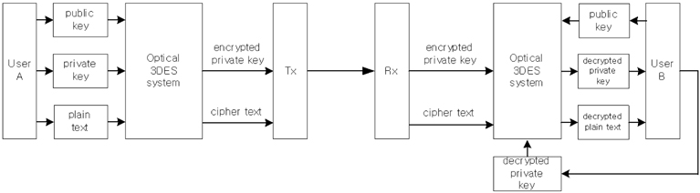
Figure 1 shows the block diagram of the proposed 3DES encryption/decryption procedure. We can modify this procedure to simultaneous watermark verification and data encryption by changing the private key with the watermark in this Fig. 1.
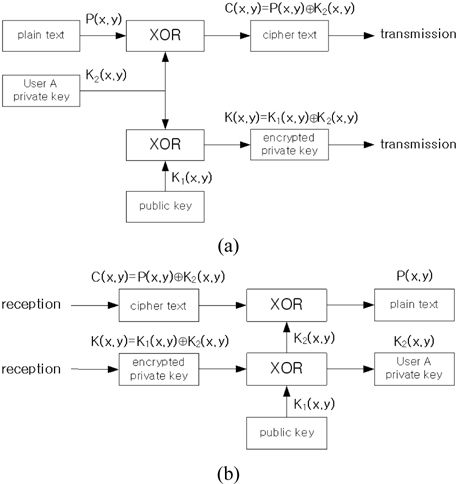
Figure 2 shows the flow chart of the encryption and decryption for the proposed 3DES. The box XOR in the figure means the exclusive-OR logic operation.
2.3. Optical XOR Operation using a Free-space Interconnected Optical Logic Gate Method
An optical logic gate processing concept can be regarded as a free-space interconnected gate with logic. The free-space optical interconnection is important not only in communication systems but also in massive digital optical computing because of its various advantages, such as its efficiency to implement logic functions and the complexity of the implementation system. In this paper, we apply a free-space interconnected optical logic gate method in order to implement an XOR logic operation in an optical way. The free-space interconnected optical logic gate method is probably a good breakthrough to solve the difficulties of input-output pattern match. In the type of data encoding, a bit of information is represented by the position of a bright spot rather than by its intensity or polarization. The advantage of the free-space interconnected optical logic gate method is that no cell coding-decoding process is required and the output has the same format as the input. In the optical configuration of a logic gate, binary input variables are spatially encoded by using two’s complement.
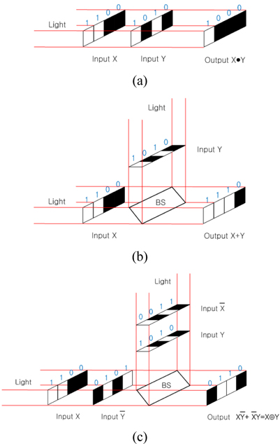
Figure 3 shows the optical schemes for bitwise logic operations using the free-space interconnected optical logic gate method, that is, the corresponding optical configurations for AND logic, OR logic, and XOR logic, respectively. Consider input variables
where symbol • represents AND logic operation. After inner production and addition are carried out pixel by pixel, the logic function on this scheme is given by
where symbols + and ⊕ represent OR and XOR logic operations, respectively.
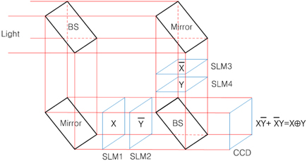
Figure 4 shows the proposed optical schematic architecture for implementing a page-oriented optical XOR operation by using the basic concept of Fig. 3. In Fig. 4, the last beam splitter is used for combining two lights passed through SLMs. Two input operands
2.4. Optical Implementation of Triple DES
The security of a symmetric cryptosystem is a function of the length of the key. The longer the key, the more resistant the security strength is. For this reason, the key length is chosen as the first parameter for specifying cryptographic algorithms. Assuming there is no better way to break the cryptosystem, other than to try every possible key with a brute force attack, the longer the key, the longer it will take to make the number of attacks necessary to find the correct key. In fact, every extra key bit generally doubles the number of possible keys and therefore increases the effort required for a successful brute force attack against most symmetric key algorithms. Generally, a key length of N bits means that 2N attempts are required. For example, there are 256 possible keys for the conventional DES and 2112 possible keys for the conventional 3DES. Even though two-key algorithm has more enhanced security strength, they require longer processing time of encryption or decryption when compared to one-key algorithm. Since the transmission technology advances, we need faster cryptosystems to catch up with the transmission speed.
In order to meet these requirements, in this paper we are going to propose a security enhancement method to strengthen 3DES algorithm. Basically, the optical system has an inherent advantage of two dimensional image data processing and fast parallel information processing time. The main idea of the proposed method is that the 3DES algorithm is implemented in an optical way and the key length is increased by expanding the key to a 2-D array. This 2-D expansion does not diminish encryption speed. With these properties, we suggest an optical implementation of XOR-based 3DES system which has 2-D page-typed plain text and security key input formats, resulting in the same 2-D cipher text output. If the 2-D key data consists of N×M pixels, then 2N×M attempts are required to find the correct key. However, the encryption speed using this XOR operation method is not affected by the data size because of parallel XOR operational processing. The symmetric encryption algorithm such as DES can be implemented optically with a bitwise XOR logical operator. Han et al. suggested optical image encryption based on XOR operation [20]. A two-input XOR gate was implemented very simply using two polarizers and two liquid crystal displays. This method can be used to implement a simple DES algorithm, but cannot be applied to the double encryption such as 3DES because of difficulty in implementing sequential optical XOR logic operations. However, our proposed method will solve the sequential XOR operations by using the free-space interconnected optical logic technique in implementing the XOR logic optically.
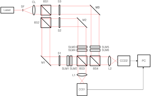
The main idea in the proposed optical 3DES method is to make a more secure cryptographic system, which is accomplished by encrypting and transmitting the individual private key and the plain text, and this encrypted private key is used to decrypt the original plain text. Referring to the block diagram of 3DES encryption and decryption procedure shown in Fig. 1, the optical 3DES system can be designed with optical components such as mirrors, beam splitters, lenses, and spatial light modulators (SLMs). Figure 5 shows the proposed optical implementation setup for 3DES using dual XOR logic operations, which is based on the free-space interconnected XOR logic operation architecture for binary data. Schematically, the optical setup contains two Mach-Zehnder type interferometers. Beam splitters BS1 and BS2 divide a collimated light into three plane waves and BS3 and BS4 combine these divided lights into two lights, resulting in records on CCDs. Also, this system is composed of six SLMs which are used for data input devices.
In order to investigate operating principles of 3DES, the flow charts shown in Fig. 2 are considered. First, let us consider the encryption procedure shown in Fig. 2(a). One plain text and two security keys are displayed on SLMs as free-space interconnected optical logic gates. Shutters S1, S2, and S3 are placed in the path of light to control encryption operations. In Fig. 5, with shutters S1, S2 open and S3 closed, the inner interferometer is used for encrypting the private key of the one user with the public(or common) key. The collimating light after being reflected by the mirror M1 illuminates the SLM1 which displays the binary private key (
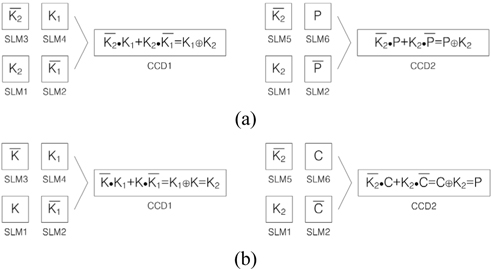
[FIG. 6.] Representations of input SLMs’ data and output CCDs’ data; (a) encryption, (b) decryption.
Second, the decryption procedure shown in Fig. 2(b) is explained as follows. In our proposed cryptographic system, the decryption can be accomplished by using the same optical 3DES system as shown in the Fig. 5. The decrypting technique is that the encrypted private key data, which is transmitted to and received by the other user, is used for decrypting the original private key of the one user. Again, this decrypted private key is used for decrypting the original plain text from the received cipher text. In Fig. 5, with shutters S1, S2 open and S3 closed, the inner interferometer is used for decrypting the private key of the one user with the known public key (
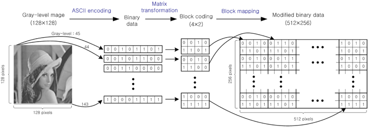
We show the performance of the proposed optical 3DES cryptographic method based on dual XOR logic operations by numerical simulations. In our method, input data to be encrypted must be binary bit data or a binary image. Therefore, a gray-level optical image to be encrypted must be converted to binary data in our proposed cryptosystem. In the previous papers [16-17], we use analog-to-digital ASCII encoding technique for converting a 256 gray-level image into the digitized 8-bits binary data. The 8-bits binary data corresponding to one gray-level value is arranged in a block having 4×2 pixels by block coding, and the converted data expands to 512×256 pixels in size by block mapping. Figure 7 shows the procedure of the proposed ASCII encoding and block mapping method for converting the 256 gray-level image into binary data.
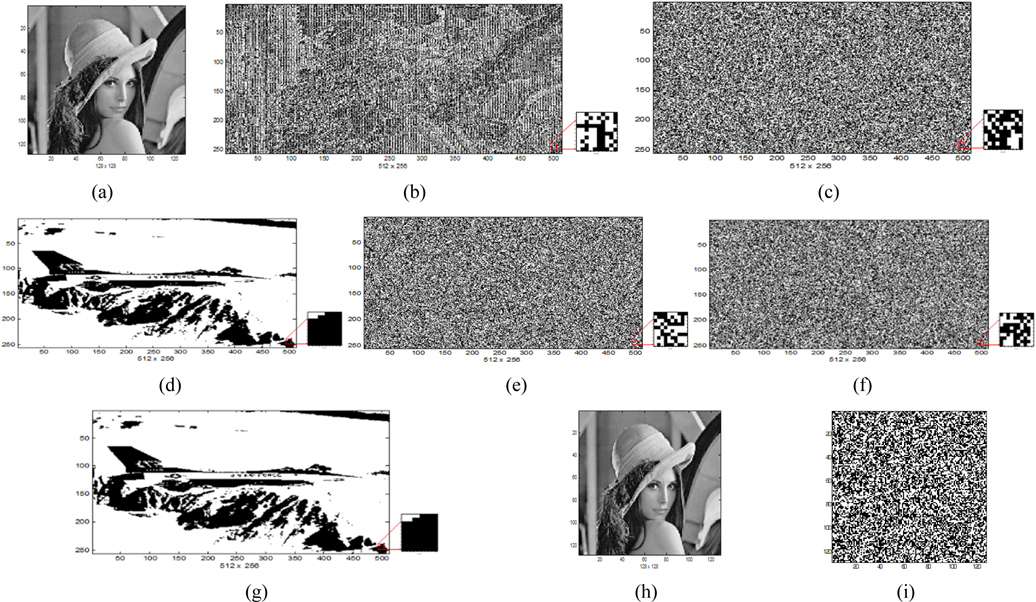
In this paper, a 256 gray-level Lena image of size 128×128 pixels shown in Fig. 8(a) is used as an input image to be encrypted. Figure 8(b) represents the converted binary data of the Lena image as the plain text to be encrypted, size of which is expanded to 512×256 pixels, where white areas have value of 1 and black areas are 0 numerically. Figure 8(c) shows a random generated binary bit code of size 512×256 pixels as a public key used for encryption and decryption, and a binary plane image of size 512×256 pixels shown in Fig. 8(d) is used as a user’s private key (or watermark) to be encrypted for key encryption. The data with 512×256 pixels in size is equivalent to (64×8)×(64×4) pixels, i.e., 64×2048 bits or 128×1024 bits. This means that our configuration has 2,048 DES blocks of data and each block uses its own random generated key to cipher block data. Because the 2-D optical system has a property of parallel processing, there is an effect that 2,048 DES blocks or 1,024 3DES blocks are encrypted simultaneously compared to similar DES operations in digital electronics. Note that this private key can be interpreted as user’s own watermark image for authentication application. Figure 8(e) and (f) show the encrypted private key by the public key and the encrypted binary data as the cipher text by the private key, respectively. These encrypted data which are recorded on CCDs have a form of randomness, and are transmitted to the other user. From the proposed optical 3DES cryptographic system, the decryption of the original private key is carried out by the correct public key and the original Lena image is decrypted by the correct decrypted private key and ASCII decoding successfully. Figure 8(g) and (h) show the exactly decrypted private key and Lena image. Figure 8(g) shows the exactly decrypted private key (or watermark) when the correct public key is used for the private key decryption, and Fig. 8(h) shows the exactly decrypted Lena image by the correctly decrypted private key. On the other hand, when we don’t know the private key information, we cannot decrypt the original Lena image. Figure 8(i) shows the decrypted false image by an incorrect private key.
We propose a novel optical implementation method of a triple DES algorithm based on dual XOR logic operations for a cryptographic system. The optical 3DES system is realized by dual XOR logic operations, where XOR logic operation is implemented by using a free-space interconnected optical logic gate method. The optical schematic of the proposed method has two Mach-Zehnder type interferometers simultaneously. The inner interferometer is used for encrypting a private key with a public key, while the outer interferometer is used for encrypting a plain text with the same private key. The suggested optical setup of the cryptosystem can also be used for the decryption process. The major merit of this optical implemented cryptography is that a vast amount of data can be processed in parallel very quickly and the encryption/decryption processing time is much faster than electronic methods. Also, the encryption/ decryption processing time does not diminish in spite of data expansion owing to the parallel processing property. The proposed system is convenient for exchanging the different private keys in the form of cipher and for decrypting the plain text only by the corresponding private key. This fact implies that our scheme can be applied to the OTP encryption if users create different private keys each time at their own discretion. Of course, the proposed dual XOR optical encryption method provides higher security strength to use double key encryption, and has an advantage of simple optical setup configuration. Our proposed method seems to perform 2,048 DES blocks or 1,024 3DES blocks cipher. Besides, because the key length is equal to 512×256 bits, 2 512×256 attempts are required to find the correct key. Computer experiments verified that the proposed method is perfect and suitable for cryptographic applications and secure communication system.