With the development of computer calculations and network connections, more and more threats and attacks are generated in information communication systems. Optical information security has attracted a lot of attention, which offers primarily two types of benefits; the first is an inherent capability for parallel and rapid processing, and the second is a concealment in any of several dimensions, such as phase or spatial frequency [1]. Optical systems have an excellent capability to encode information. In general, there are three main classes of cryptography for implementing optical image encryption. The first is encrypting an image to one stationary white noise-like ciphertext utilizing an encryption key. The second is multiple-image encryption (MIE) which encrypts multiple images to one ciphertext by taking advantage of different encryption keys. The double random phase encoding (DRPE) method and the iterative phase-retrieval algorithm are extensively utilized in both of those encryption methods. In this paper we call the third one (encrypting one image into multiple ciphertexts) splitencryption (SE) for simplicity.
Encryption utilizing the DRPE method includes both symmetric and asymmetric cryptographic algorithms because the decryption key could be identical to or the conjugate with the encryption key. Two random phase-only functions (POFs) are utilized in this method. The first POF improves the signal of a charge-coupled device (CCD), and the second POF is the encryption key in the system [2]. However, when the complex conjugate of the information obtained in the frequency domain is considered as the ciphertext, the decryption key must be identical to the second random POF so-called symmetric cryptography. When the information obtained in the frequency domain is considered as the ciphertext, the decryption key has to be the conjugate of the second random POF-asymmetric cryptography. Indeed, the DRPE method is used in different interferometries and transforms to implement optical information security. Refregier and Javidi first suggested the DRPE method [3] that has been exhaustively developed in recent decades. As phase-shifting interferometry is developed, Lee and Gil applied the DRPE method to four-step phaseshifting interferometry for implementing optical encryption [4]. Shen et al. applied the DRPE method to three-step phase shifting interferometry to implement optical encryption [5]. Jeon and Gil applied DRPE to two-step phase-shifting interferometry to accomplish optical encryption [6]. Moreover, it is also employed in the information-hiding technique [7] and watermarking [8]. The encrypted optical field can be transmitted electronically. But DRPE cryptography is vulnerable to attack if the second phase-only function in the encrypted processing is obtained.
MIE encrypts several images into one single ciphertext. This encryption technique can hide more information, so it is more complicated. Meanwhile, most algorithms are timeconsuming. The biggest problem is crosstalk, which means how to reconstruct every single image in high quality from the only one single ciphertext. Because of this, MIE is more suitable for binary images than gray images. Shi et al. employed cascade phase retrieval algorithms to hide three different images together in the Fresnel domain [9]. He et al. proposed an MIE scheme to encrypt two objects into one ciphertext by utilizing DRPE and phase-shifting methods [10]. The crosstalk problem was depressed by thresholding and binarization. Situ and Zhang introduced the wavelength multiplexing technique into a double randomphase encoding system to encrypt multiple images [11]. Liu and Liu proposed an encryption scheme, which simultaneously encrypts two images into a single image by of the four ciphertexts and crop them to a quarter of the original size. They subsequently combined the four new quarter-size ciphertexts into one new original-size ciphertext by placing them into each quadrant [13]. Chang et al. proposed a novel wavelength-multiplexing algorithm based on the cascaded phase-only function architecture and that scheme significantly reduced the crosstalk problem [14]. fractional Fourier transform with different fractional orders [12]. Liu et al. proposed a novel MIE method to overcome the crosstalk problem, which is to abandon all high frequencies
Optical image split-encryption has been growing rapidly since Zhang and Wang suggested it for the first time [15]. The authors modulated the optical field in the Fresnel domain to two phase-only masks (POMs) to be allocated to two authorized users. In the decryption processing, if and only if the authorized users get together, the reconstructed image can be obtained by an inverse Fresnel transform. Unlike DRPE, the SE scheme does not need an explicit key for the ciphertext. In the SE scheme, one ciphertext also plays a role of the key of another ciphertext. Similarly, unlike MIE, the SE scheme does not introduce any time-consuming iterative phase-retrieval methods. Therefore, the SE scheme is more efficient and more convenient to manipulate. But there is a serious silhouette problem in the SE scheme. The silhouette information of the original image is visible (when reconstructed) in both of the two POMs. Addressing this issue, Wang and Zhao introduced a third random POM for effectively eliminating the silhouette problem [16], but this scheme only focused on removing the silhouette problem when reconstructing a single POM. If the product of two specific POMs is reconstructed, the silhouette information will become visible. Kumar et al. inserted a chaotic algorithm jigsaw transform to postprocessing of the two POMs [17], which can also effectively solve the silhouette problem. Even though the number of encrypted images is less than the last scheme, it also involves first inverse jigsaw transform and then inverse Fresnel transform in the decryption processing, which is the inverse manipulation of the encryption procedure, and both encryption and decryption require one extra transform. It is complicated and not distinctive. All of the above papers concentrated on the Fresnel domain. Jia et al. proposed cryptography based on the object plane to convert the original image to two phase-only functions via manipulation [18]. This can remove the silhouette problem as well. Nevertheless, it is only suitable for binary images, and cannot work on gray images.
In this paper, we propose an optical image split-encryption scheme to overcome the flaws enumerated in all the papers above. During the encryption process, the original image uses a random phase-only function introduced to influence phase distribution of the preliminary ciphertexts. Then we obtain a new complex original image and convert it to two phase-only functions that are the preliminary ciphertexts. Next, the optical fields of these two phaseonly functions can be obtained by taking advantage of a two-step phase-shifting method. These two encrypted optical fields cooperate with each other to reconstruct the original image. This proposed scheme requires no extra iterative algorithms, chaotic algorithms and random POMs in the Fresnel domain. It can be applied not only to a binary image but also to a gray image. The most important characteristic is utilizing only two ciphertexts to completely eliminate the silhouette problem.
The principles of the proposed optical image splitencryption are introduced in Section 2. In Section 3, computer simulation is described to demonstrate the feasibility of the proposed SE scheme. Error analysis is described in Section 4. Concluding comments are shown in Section 5.
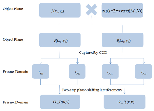
Fresnel transforms are based on Fourier transforms, and Fourier transforms obey the distributive law, so Fresnel transforms also obey the distributive law. This induces the proposed encryption scheme, whereby f (x0 , y0) is assumed to be the original image (real-valued data), which is multiplied by a random phase-only function to obtain a new image obj(x0 , y0) , represented mathematically as follows:
where M and N are sampling numbers along the x-axis and y-axis of the original image. The purpose of rand(M,N) is to generate an M × N random matrix distributed from 0 to 1. Throughout the remainder of this paper, the coordinates (x0 , y0) , (u,v) and (x, y) represent the object plane, frequency plane and reconstructed plane, respectively. The essential purpose of the random POF introduced in Eq. (1) is to widen the dynamic range of the phase in the two POFs, P1(x0 , y0) and P2(x0 , y0). The amplitudes of these two POFs are the constant 1. The rest of the required equations are as follows:
where obj _ in(x0 , y0) , and obj _ phase(x0 , y0) denote the intensity and phase of obj(x0 , y0), respectively. P1(x0 , y0) and P2(x0 , y0) are essentially two split POFs that will be modulated on the spatial light modulator, and abs() and arg() denote the modulus and phase, respectively, of the new image obj(x0 , y0) . Therefore, the new image obj(x0 , y0) consists of P1(x0 , y0) and P2(x0 , y0) .
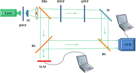
The ideal encryption system can approach both encryption and decryption manipulations in an optical manner, but just one process could be implemented optically. Most researchers investigate decryption optically owing to restrictions such as component limitations and difficulty in optical setup configuration, etc. We adopt optical encryption to obtain the final ciphertexts O_ P1(u,v) and O _ P2(u, v) in this proposed scheme. Intensity-sensitive devices, such as CCD cameras, can only capture the intensity portion and cannot capture the phase portion of an optical field. Therefore, two-step phase-shifting interferometry is needed to calculate the phase portion and subsequently accomplish the encryption manipulation of the proposed scheme. The schematic diagram of the setup is depicted in Fig. 1.
The mathematical expressions of the encryption process are described as follows:
where FrT denotes the Fresnel transform (Note: ∗ represents the complex conjugate). According to Euler’s formula cosθ = [exp(iθ) + exp(−iθ)] / 2 , we can obtain the result of Eq. (8). In addition, the more mathematical information is introduced specifically by Goodman [19]. AP1 , AP2 and φP1 , φP2 are assumed to be amplitudes and phases of O_ P1(u,v) and O_ P2(u,v) , respectively. Assume the reference beam r = R× exp( i ∗φr) , where R represents the constant amplitude and φr represents the constant phase. Then the quarter waveplate is tilted by π / 2 and the second hologram IP12 is captured. According to Eq. (10) we can calculate O_ P1(u,v) . DCP1 in Eq. (10) denotes the zero-order light of the hologram generated from P1(x0 , y0) , which consists of AP12 and R2 (DCP1 = AP12 + R2 ). DCP2 in Eq. (14) denotes the zero-order light of the hologram generated from P2(x0 , y0) , which is presented as DCP2 = AP22 + R2 . It was introduced specifically by Shen et al. [5]. And O_ P2(u,v) generated from P2(x0 , y0) , can be calculated in the identical manner. For the sake of simplicity, we assume the phase of the reference beam in the Fresnel domain φr is 0. The encryption flow chart is depicted in Fig. 2.
Here, the optical fields O_ P1(u,v) and O_ P2(u,v) that are generated from POFs P1(x0 , y0) and P2(x0 , y0) can be obtained from the above process. Therefore,
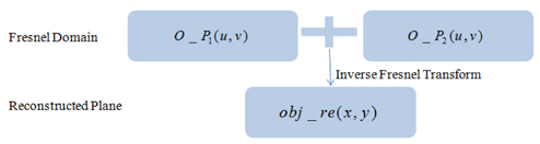
where IFrT denotes the inverse Fresnel transform. The intensity of obj _ re(x, y) is technically the reconstructed image.
The decryption flow chart represented in Eq. (15) is depicted in Fig. 3.
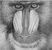
The feasibility of the proposed scheme was verified with a 256× 256 grayscale Baboon image (Fig. 4). The phase portions of the two POFs are depicted in Fig. 5(a) and Fig. 6(a), respectively.
No silhouette information of the original image can be seen in Fig. 5(c), which is the reconstructed image generated from O_ P1(u,v) in the analog. In addition, no silhouette information of the original image can be seen in Fig. 6(c), which is generated from O_ P2(u,v) in the analog. If and only if optical fields of O_ P1(u,v) and O_ P2(u,v) are added together, can the original image be reconstructed. Fig. 7 shows the reconstructed image, decrypted correctly, looks nearly identical to the original image (shown in Fig. 4) .
Relative error ( RE ) is introduced as the criterion of the reconstructed image’s quality and is expressed as follows [15]:
where R(m,n) denotes the intensity of the reconstructed image and O(m,n) denotes the original image. We see that RE is smaller, and the gray-scale value of the reconstructed image is closer to the original image in terms of Eq. (16). This also means the higher the RE value of the single reconstructed image, the more irrelevant between the original image and the reconstructed image. However, when RE > 0.2 , theoretically, one cannot distinguish the decrypted image with the naked eye [15].
The RE of the recovered image shown in Fig. 7 is 7.6061×10⁻³¹ . The recovered image generated from a single ciphertext is shown in Fig. 5(c) and 6(c). The RE values are both 0.6854. The two RE values are much more than 0.2, and the silhouette information is totally invisible.
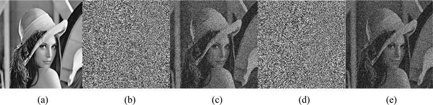
For comparison, the method of Wang and Zhao [16] was simulated again for this paper. Some of the results are shown in Fig. 8.
They introduced a random POF to split the complex amplitude of the optical field into POF1, POF2 and POF3; the RE value of the three images reconstructed from those three POFs is around 0.4. Silhouette information is invisible in the three reconstructed images, which have RE values that are still lower than our RE values of the single ciphertext. And the silhouette problem appears when reconstructing the product of the specific two ciphertexts, as seen in Fig. 8(c) and (e). The RE values of Fig. 8(c) and (e) are 0.1567 and 0.1898, respectively, both of which are less than 0.2; therefore, the silhouette problem shows up.
A digital hologram recorded on a CCD is quantized with 256 levels. So a gray-level error on CCD camera pixels can be generated due to a small intensity variation, which is the so-called quantization error [2]. If there is no error, the decryption equation expression should be like Eq. (7), Eq. (11) and Eq. (15). However, the error appears when the CCD camera captures the optical field O_ P1(u,v) and O_ P2(u,v) . This will introduce two amplitude errors and two phase errors, which are mathematically presented in the following equations:
Where O_ P1real and O_ P2real denote the real calculated encrypted optical fields, respectively. EP1 stands for the amplitude error distributed from 0 to 255, and eP1 stands for the phase error distributed from −π to π , which probably both appear in the encrypted optical field O_ P1(u,v) . EP2 and eP2 are the amplitude error and the phase error, which appear in the encrypted optical field O_ P2(u,v). EP1 , eP1 , EP2 , and eP2 will introduce the white noise into the decrypted image. However, AP1 and AP2 are not distributed in the range [0, 255]; they should first be reset in [0,255].
The purpose of the error analysis is to calculate what amplitude error range (AER) and phase error range (PER) the reconstructed image can tolerate for the naked eye. First, a toleration criterion should be determined. The different RE value and the corresponding reconstructed images are depicted as follows, where we calculated many different images. The results of the 256× 256 grayscale image Lena and the 256× 256 grayscale image Baboon are depicted in this paper for the investigation of the tolerated boundary RE value.
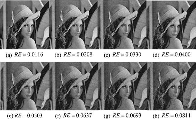
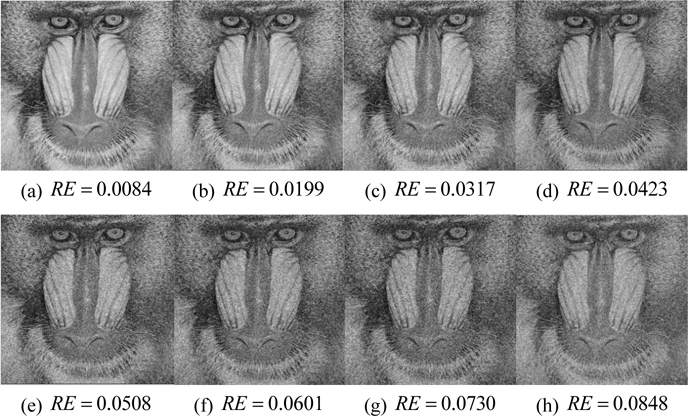
All of the images depicted in Fig. 9 are the reconstructed images from the optical fields with amplitude errors or phase errors, or both. For example, the RE value is equivalent to 0.0116 in Fig. 9(a). The RE value is equivalent to 0.0811 in Fig. 9(h). The noise increases from Fig. 9(a) to (h). Still acceptable to the naked eye is Fig. 9(g), although the dimension of the noise has increased; the image quality worsens in Fig. 9(h). In addition, all of the attached images are 43% of the original size. Therefore, the noise in Fig. 9(h) cannot be tolerated.
The results in Fig. 10 are similar to those in Fig. 9. The noise is acceptable to the naked eye from Fig. 10(a) to (f). However, the noise increases suddenly between Fig. 10(g) and (h), as seen in the nose of the Baboon images. Therefore, RE=0.07 is determined as a boundary criterion. The other verified images also give uniform results.
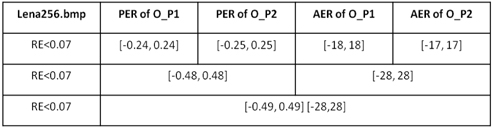
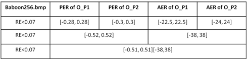
Here, the Lena and Baboon images are both utilized to analyze the AER and PER with RE < 0.07 . However, only the curve graphs of the Baboon image are included in this paper.
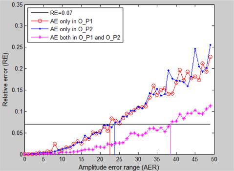
In Fig. 11, the full black line represents the threshold line RE = 0.07 . AE means amplitude error, and O_P1, O_P2 stand for single ciphertext O_ P1(u,v) and single ciphertext O_ P2(u,v) , respectively. The red line with circles represents errors that only happened in the amplitude portion of O_ P1(u,v) , which shows the tolerated AER is [-22.5, 22.5] with RE < 0.07 . The blue line with dots represents errors that only happened in the amplitude portion of O_ P2(u,v) , which shows the tolerated AER is [-24, 24] with RE < 0.07 . The magenta line with asterisks represents errors that happened in the amplitude portion of both O_ P1(u,v) and O_ P2(u,v) , which shows the tolerated AER extends to [-38, 38] with RE < 0.07 .
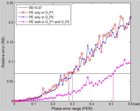
In Fig. 12, the full black line represents the threshold line RE = 0.07 . Phase error (PE) is in rads. O_P1, O_P2 represent single ciphertext O_ P1(u,v) and single ciphertext O_ P2(u,v) , respectively. The red line with circles represents errors that only happened in the phase portion of O_ P1(u,v) , which shows the tolerated PER is [-0.28, 0.28] with RE < 0.07 . The blue line with dots represents errors that only happened in the phase portion of O_ P2(u,v) , which shows the tolerated PER is [-0.3, 0.3] on condition RE < 0.07 . The magenta line with asterisks represents errors that happened in both phase portions of O_ P1(u,v) and O_ P2(u,v) , which shows the tolerated AER extends to [-0.52, 0.52] with RE < 0.07 .
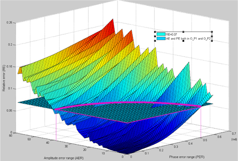
In Fig. 13, the plane represents the threshold plane RE = 0.07 . The curved surface represent the PE and AE that happen in both O_ P1(u,v) and O_ P2(u,v) . When these four kinds of errors happen at the same time, the tolerated PER and AER form a closed area surrounded by the closed magenta line.
The data in Table 1 illustrate Fig. 11, Fig. 12, and Fig. 13. It is worthwhile to note that the maximum AER and PER are taken from Fig. 13, assuming there is no influence from other different categories of errors. In these three figures, the last point not exceeding the black line is taken into account. In addition, although the RE curves increase tortuously as AER or PER expands, the shapes of the curves rise steadily in the long term.
We conducted the same process with the Lena image, and the results are depicted in Table 2. According to Table 1, Table 2 and other data not listed in this paper, different images have different tolerated PERs and AERs. However, if both of the phase errors of the optical field work together, the tolerated PER will increase to almost twice that seen when PE happens in a single optical field. If both of the amplitude errors (AEs) of the optical field work together, the tolerated AER will increase to almost twice when AE happens in single ciphertext. It means the PE in O_ P2(u,v) and PE in O_ P1(u,v) influence each other in a promotive way, as does AE in O_ P1(u,v) and AE in O_ P2(u,v) . However, if the four kinds of errors happen at the same time, the phase error and the amplitude error influence each other antagonistically, as seen from the thick magenta line in Fig. 13.
The proposed optical image split-encryption scheme focuses on the optical information encryption for converting original plaintext to multiple ciphertexts. It requires no complicated iterative algorithms or chaotic transforms. Moreover, fewer phase-only functions need to be split. It can be applied to gray images, and introduces only one random POF for influencing subsequent encryption. The encryption procedure is to split the original image into two POFs mathematically, subsequently obtain two authorized ciphertexts generated from those two POFs by taking advantage of a two-step phase-shifting method. The original image can be reconstructed with an extremely small relative error RE = 7.6061×10⁻³¹ , if and only if these two ciphertexts are combined. During the verification process, no silhouette information can be seen with the naked eye in either reconstructed image generated from a single POF. In addition, both RE values of the reconstructed image generated from a single POF are around 0.68, which is much better than previous SE schemes. We also demonstrate that solo phase errors or amplitude errors in two ciphertexts can influence each other in a promotive way, but when the four kinds of errors happen at the same time, PE and AE influence each other antagonistically.