A telescope for space exploration requires numerous types of technology. In particular, the imaging system is one of the most essential components for scientific research. Generally, astronomical space telescopes and satellite cameras use a reflecting optical system with conic mirrors because the conic surface can be very precise, and the radiation tolerance is much higher than that of refracting lens material [1, 2]. There are many types of space optics with one or two mirrors used for low-resolution imaging or spectroscopic observation [3, 4]. Recent imaging sensor technology also allows us to design a wider field of view and achieve higher resolution in space imaging with various satellite platforms. In this paper, we present the optical design of a small reflecting telescope for a 3U CubeSat platform.
CubeSat is a class of nano-satellites initially developed at Stanford University and California Polytechnic State University at San Louis Obispo to facilitate low-cost access to space [5]. The CubeSat platform is a standardized configuration, consisting of one to three 10 cm × 10 cm × 10 cm units (1, 2, or 3 “U”s) arranged in a row, where 1U has a mass of 1.33 kg [6, 7]. It is launched as a piggyback secondary payload on a large launch vehicle using the Poly-Picosatellite Orbital Deployer (P-POD). There are many kinds of 3U CubeSat missions for scientific research and technical experiments [8, 9]. Imaging satellites based on CubeSat have mostly been implemented for Earth-observing missions.
Most imaging CubeSats have refraction lens mount optics because it is difficult to fit a reflecting telescope into a CubeSat. Lens mount optics has disadvantages such as the darkening effect caused by space radiation and, misalignment and fragility caused by vibration and thermal effects.
In this paper, we design the optics of a reflecting telescope for a CubeSat unlike previous missions. A major objective is to acquire high-quality images of the Earth’s surface with our new, small reflecting telescope.
II. BASIC REQUIREMENTS FOR THE CUBESAT TELESCOPE
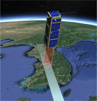
This research involves the design of a conventional imaging camera system with a small reflecting telescope for a CubeSat mission. We estimate a ~700 km altitude in sun synchronous orbit with a standard CubeSat platform. Figure 1 shows the conceptual operation of the push-broom imaging mode to scan or shoot the Earth’s surface as the CubeSat moves along its orbit. In this section, we describe the fundamental requirements for designing the reflecting telescope for a 3U CubeSat mission (10 cm × 10 cm × 34 cm).
2.2. Mechanical Design Requirements
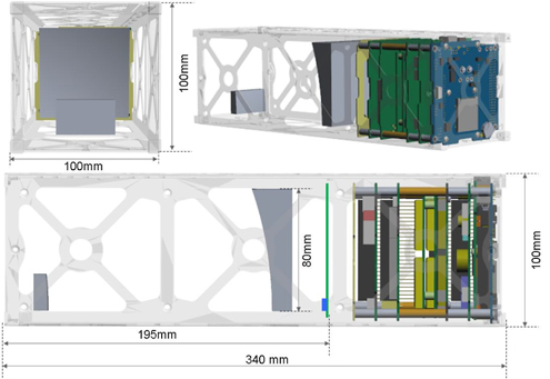
The main constraint of the optical design is the space allowance in CubeSat. There should be no interference in the optical path within the limited CubeSat dimensions. The CubeSat should have avionic electronics and basic structures. Therefore, the telescope space is limited by these constraints. In this design, the minimum space for avionics electronics is 10 cm × 10 cm × 10 cm, and other structural parts require 10 cm × 10 cm × 5 cm. Therefore, the maximum allowed space for the telescope is 10 cm × 10 cm × 19 cm. However, the telescope optics should be installed within a space of 8 cm × 8 cm × 19 cm in order to allow for installation of a support structure for the telescope optics and satellite structure. For this reason, we configured the optics within a space of 8 cm x 8 cm x 19 cm, as shown in Fig. 2.
The main purpose of this telescope optics system is a fine resolution image of Earth’s surface with the CubeSat application. In the case of the CubeSat mission, we can easily find an imaging instrument with a refraction lens mount within this platform because reflecting telescope optics is difficult to fit into a tiny space [7]. In this paper, we design a reflecting telescope optics system unlike the refraction lens design.
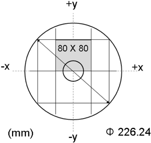
The telescope design parameters take into account several volume limitations. Two-mirror optics is a primary consideration; hence, a short focal length is also prioritized. In this case, the dimensions of the primary mirror must be within 8 cm × 8 cm, to fit into the CubeSat envelope. The field of view (FOV) is small in two-mirror optical telescopes; for example, the FOV for the Ritchey-Chretien optical system, which has the largest FOV, is only a few minutes [10]. Therefore, we aim to increase the diameter to achieve a larger FOV compared to that in the Ritchey-Chretien system. Thus, the primary mirror shape becomes a square, which cuts off the edges from a round mirror, as shown in Fig. 3. The idea is based on the off-axis segmented technique in astronomical telescope applications. We set the focal image plane area to 5 mm diameter because the CMOS image sensing area cannot exceed 4.5 mm. Table 1 shows the optical design parameters for our design. In this table we estimate the ground resolving distance based on the geometrical resolution, without diffraction. In the optical design process the diffraction effect should be of concern, since the detectors can be chosen scientifically so that more energy is collected each instant by every pixel in the FOV. [11].
[TABLE 1.] Design specifications of the telescope
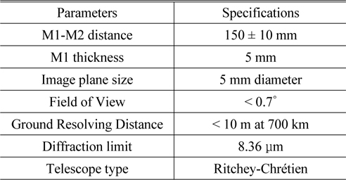
Design specifications of the telescope
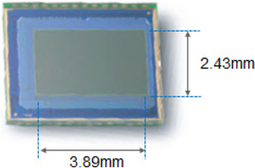
There are many kinds of sensors used to acquire an image. A CCD device is commonly used for astronomical observations due to its many advantages, such as a large full-well capacity, 100% fill factor, and low readout noise compared to a CMOS image sensor. In this study, however, we choose a CMOS image sensor because it has various pixel sizes and windowing readout mode, and low power consumption, unlike the CCD image sensor. In particular, windowing readout mode is very useful for Earth observation, to overcome the image blur produced by the satellite sweep speed during exposure. Our observation target is the day-time Earth surface, which is bright enough to allow collection of images with CMOS image sensors in the designed telescope. For our optical design, we choose the CMOS image sensor OV9712 produced by Omnivision. The pixel size is 3 μm × 3 μm and the pixel array is 1280 × 800. Table 1 describes the CMOS image sensor used in our design.
III. OPTICAL DESIGN AND ANALYSIS
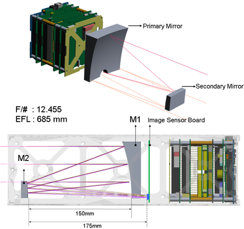
The telescope is a conventional two-mirror telescope. We used part of a 226.24 mm diameter mirror as the telescope’s primary mirror. It is a modified off-axis segmented method, as in astronomical observation. The primary and secondary mirrors are rectangular with dimensions of 80 mm × 80 mm and 41 mm × 24 mm, respectively. The rectangular shape maximizes captured light in the rectangular CubeSat body. Figure 5 shows the design layout in which the focal plane is located behind the primary mirror. Table 3 shows the data sheet for the optical design.
[TABLE 2.] Imaging sensor specifications
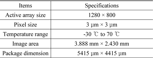
Imaging sensor specifications
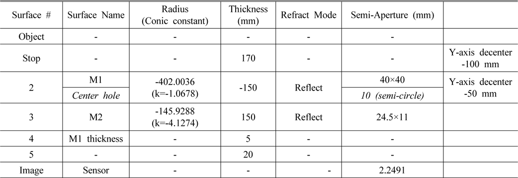
Lens data sheet
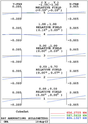
3.2. Optical Performance Analysis
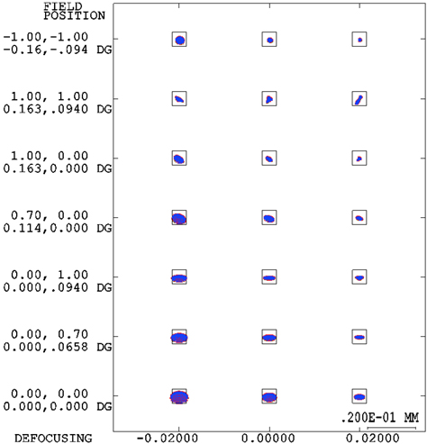
The analysis was carried out with the Code-V optical design program. Figure 6 shows a spot diagram that includes the size and shape of the spot for all visible wavelengths. The spot size indicates that the outermost field (0, 0.094°) and optical axis are 2.3
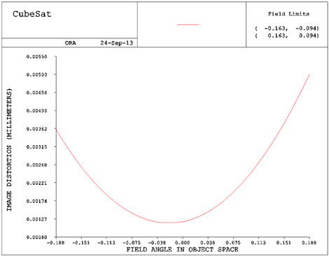
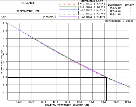
This size is slightly larger than 2 pixels. We also investigated astigmatism and distortion; the field curve is presented in Fig. 7. The distortion is no greater than 2 pixels in scale around the full field, and there is no chromatic aberration due to the reflecting mirror system. We identified the astigmatism from the MTF diagram as shown in Fig. 8, where the solid line is the MTF value of the radial component of the curve, and the dashed line is the tangential component of the curve. The camera resolution is represented by Eq. (1) in the color image array sensor.
We observe that the minimum MTF value appears over 0.3 at the 82.26 lp/mm. This is the diffraction MTF. In this case, the tangential and sagittal MTF are a little bit different. On the other hand, this design shows a small amount of fifth-order coma and large-angle astigmatism, and presents a field curvature effect that is relatively much larger than others, as shown in Fig. 9.
In this paper we present the optical design of a small reflecting telescope for a CubeSat application. This research considers issues pertaining to the assembly and manufacture of the rectangular mirror, which is designed within a space limitation. We chose a reflecting mirror to obtain high resolution with a small focal length and EPD in a 3U CubeSat.
A recent CMOS image sensor with tiny pixel size and large array also enables us to design the reflecting telescope in this study. It uses a Ritchey-Chrétien optical system, and its MTF is expected to be about 0.3 with a 3.2 mm × 2.8 mm image area. The results show that theoretically it can take images of a ~4 km × ~2.3 km area of the Earth’s surface at 700 km altitude. This telescope shows a reasonable design to obtain a more detailed image with a CubeSat. These results will be used in space exploration with CubeSat missions.