Three-dimensional (3D) imaging techniques have been considered as an important issue in the computer vision, target tracking, object recognition, and so on [1-5].Various methods for capturing and visualization of 3D objects in space have been studied [6-14] including integral imaging, synthetic aperture integral imaging (SAII) and axially distributed image sensing (ADS). Among them, the extended version of ADS was reported called axially distributed stereo sensing (ADSS) which is implemented using a stereo camera [14]. In this method, a stereo camera is translated along its optical axis to obtain multiple image pairs and the computational reconstruction is implemented by the uniform superposition of the resized elemental image pairs. This can solve the problem that the collection of 3D information is not uniform across the sensor in the conventional ADS system.
Recently, the resolution analysis methods for various 3D imaging systems under the equally-constrained resources have been reported [15-18]. In 2012, the
In this paper, we propose a new framework for performance evaluation of ADSS systems under the equally-constrained resources. The evaluation parameters are a fixed number of pixels, a fixed moving distance, a fixed pixel size, and so on. For the resolution analysis of the proposed ADSS framework, we use the two point sources resolution criterion [15]. We evaluate the depth resolution through the Monte Carlo simulations.
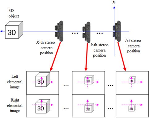
In general, the ADSS method is composed of a pickup part and a digital reconstruction part [14]. Figure 1 shows the total system structure of the ADSS. In the pickup part of the ADSS as shown in Fig. 1, we record an elemental image pair using stereo cameras with different distances. And, the distance between the two cameras is
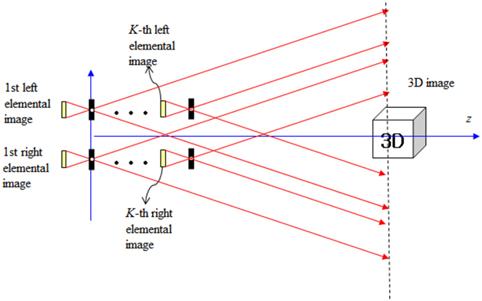
With the recorded multiple elemental image pairs, we can generate 3D sliced images in the digital reconstruction part of the ADSS which is shown in Fig. 2. The digital reconstruction process of 3D objects is the same with the inverse process of ADSS pickup. It can be implemented on the basis of an inverse mapping procedure through a virtual pinhole model as shown in Fig. 2.
Let us assume that the first pinhole is located at
where
In fact, the conventional ADS system cannot capture the correct 3D information near the optical axis. However, the ADSS system can overcome this problem by generating 3D images near the optical axis.
III. RESOLUTION ANALYSIS FOR ADSS SYSTEM
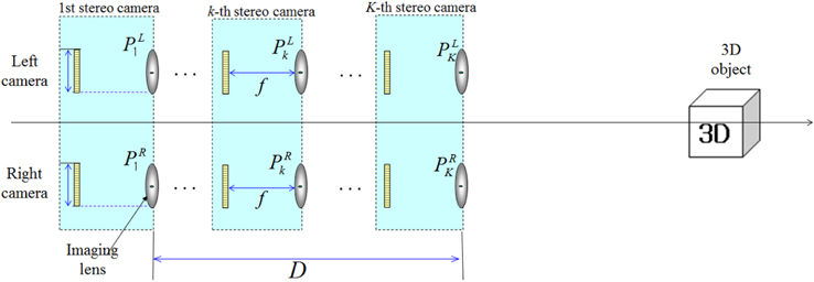
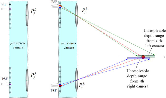
Figure 3 shows the general framework of ADSS system with stereo camera located at
In the ADSS framework as shown in Fig. 3, we can vary the positions of the stereo camera by
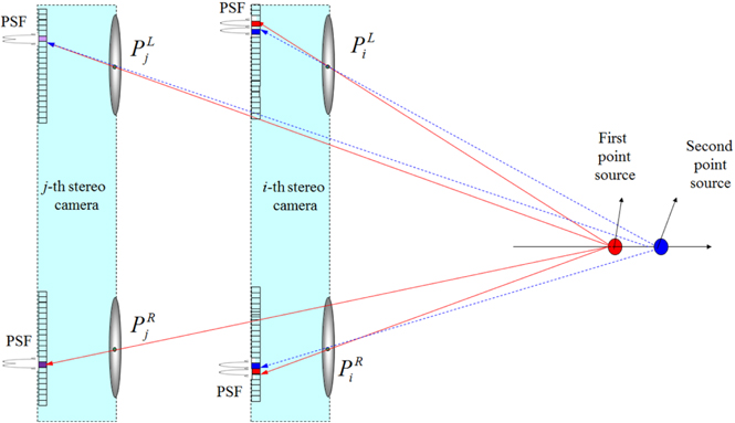
In this paper, we want to analyze the resolution performance for the ADSS framework as shown in Fig. 4. To do so, the resolution analysis method based on two point sources resolution criteria is utilized [15]. We modified this analysis method into stereo camera case in this paper.
For simplicity, we present one-dimensional notation. We assume that there are two close point sources in space as shown in Fig. 4. We first find the mapping pixel index for the first point source located at (
where
where⌈.⌉is the rounding operator.
Next, we calculate the unresolvable pixel area for the mapping pixels. The unresolvable pixel area means that two point sources cannot be separated within a single pixel. When the position of the second point source is located close to the first point source, we can resolve two point sources if the second point source is registered by at least one sensor so that it is on a pixel that is adjacent to the pixel that registered the first PSF. But, if the second PSF falls on the same pixel that recorded the PSF of the imaging lens for the first point source, we cannot resolve them. Based on this unresolved area, we can calculate the depth resolution.
Now let us consider the second point source located at (
where
Then, we want to find the unresolvable pixel area for the left and right cameras. The unresolvable pixel area of the second point source for the mapping pixel is calculated by using ray back-projection into the plane of two point sources as shown in Fig. 5. They are given by the following equations, respectively.
Finally, to calculate the depth resolution, we will find the common area for the unresolvable pixel areas calculated from all stereo cameras. The depth resolution can be considered as the common intersection of all unresolvable pixel ranges. Thus, the depth resolution for ADSS system becomes
IV. MONTE CARLO SIMULATIONS AND RESULTS
For the proposed framework of the ADSS system, the Monte Carlo simulations were performed by computer. We calculated the depth resolution statistically using the two point sources resolution analysis method. In our Monte Carlo simulation, two point sources were located longitudinally far from the stereo camera as shown in Fig. 4. We selected the random position of the first point source. And the second point source is moved in the longitudinal direction. Table 1 shows our experimental conditions of the Monte Carlo simulation for the proposed ADSS system.
[TABLE 1.] Experimental conditions for Monte Carlo simulation
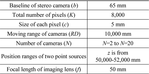
Experimental conditions for Monte Carlo simulation
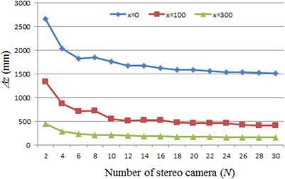
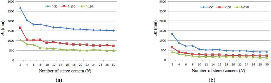
We selected the random locations of two point sources with 4,000 trials for the Monte Carlo simulations. The depth resolutions for this experiment were calculated as the sample mean. For the several parameters, we carried out the simulations in terms of the depth resolution for ADSS frameworks. First experiment is the calculation of depth resolution according to the number of cameras. The result is shown in Fig. 6. According to the distance (
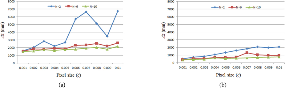
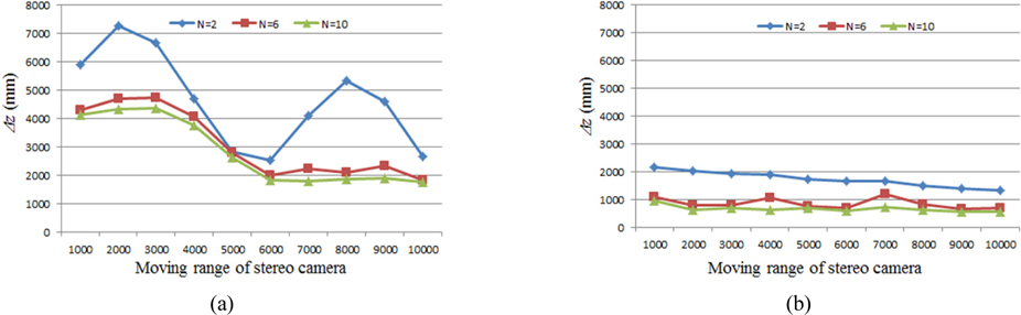
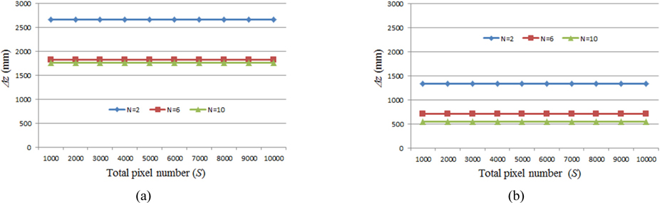
Figure 7 shows the depth resolution results according to the number of cameras and focal length of imaging lens when
In conclusion, we have analyzed the depth resolution for various ADSS frameworks under fixed-constrained resources. To evaluate the system performance of ADSS, we have considered system parameters including the number of cameras, the number of pixels, pixel size, and focal length. From the computational simulation, it is seen that the depth resolution in ADSS system can be improved with the large number of cameras and the large distance between optical axis and point source plane. The proposed analysis method may be one of a promising tool to design a practical ADSS system.