The regenerative optical amplifier has attracted intense interest for its advantages of achieving high-stability, highpeak- power amplification for ultra short optical pulses. In the amplification of an optical pulse train with high repetition rate, a regenerative amplifier can achieve high gain as well as maintaining low waveform distortion and low noise. Regenerative amplifier systems have been demonstrated as preamplifiers for high power laser systems and operation in a wide wavelength region has been reported by applying different gain media including neodymium glass [1-2], Nd:YLF [3], Cr:LiSAF and Ti:sapphire [4-5]. The rareearth doped fiber lasers and amplifiers have developed fast due to their compact size, good stability and outstanding thermo-optical properties [6-8].
There are two kinds of regenerative fiber amplifiers reported in the past. The first kind is based on a fiber loop amplifier without any optical switch [9-12]. This kind of design has simpler structure and also has the potential to support the amplification of the pulse train with high repetition rate. The pump power is under the self-lasing threshold. The second kind has an optical switch in the amplifier [13-16]. The usage of an optical switch provides some flexibility to amplify high-repetition-rate pulses.
Many works on the first kind of regenerative amplifier for CW signals have been reported. The first regenerative fiber amplifier had been demonstrated in 1999 [9]. The gain medium of this amplifier is erbium-doped fiber. It has been reported that the CW signal regenerative amplifier has higher gain and lower noise over the conventional singlepass configuration. Saturation characteristics of regenerative Erbium-doped fiber amplifier and gain characteristics of different pump structure were also discussed by Teyo [10-11]. The further dynamic characteristics of the regenerative erbium-doped fiber ring amplifier were discussed by B.P. Singh [12]. It was found that a low optical feedback level will lead to improvements in the gain and noise performance of the optical amplifier. But the pulses amplification of this type of regenerative amplifier was not demonstrated. So it is necessary to investigate the pulses amplification of this kind of regenerative amplifiers.
Later, the second kind of regenerative amplifier for Q-switched pulses with low repetition rate and nanosecond pulse width have also been investigated [13-16]. In contrast to the first kind, the second kind of regenerative amplifier is of optical switch, such as AOM. The structure of regenerative amplifiers is different from the regenerative amplifiers described in ref 9-12. In 2006, Yang demonstrated an all-fiber-based ring-cavity Q-Switched regenerative Erdoped amplifier that achieved 40 dB gain and 30nJ output pulse energy at 1.53 μm [13]. In 2009, a photonic crystal fiber-based regenerative amplifier at 1078 nm was reported [14]. The gain medium of the experiment is a low-NA, single-mode, Yb-doped polarizing photonic crystal fiber. The gain of 69 dB was reached when the input signal pulse energy is 20pJ in a 12ns pulse at a 3 kHz repetition rate. In 2011, a Yb-doped all-fiber regenerative amplifier at 1053 nm was demonstrated. Nanosecond optical pulses were amplified at pulse energy level of 15pJ to 240nJ and gain of 42 dB was achieved [15]. A negative-feedback system was employed in the fiber regenerative amplifier to control the cavity dynamics and stabilize the output pulse energy [16]. However, there has been no work ever reported on the regenerative amplification of the pulse train with high repetition rate and picosecond pulse width. In fact, this kind of regenerative fiber amplifier has difficulty in realizing the high repetition rate pulses amplification because a pulse must circulate through the fiber many times before the saturation. A high-repetition-rate picosecond pulse train is usually generated either in mode-locked fiber lasers or by optical modulation in optical communication systems. Amplification of these pulse trains has significant importance for applications including optical communication, sensing and material processing, etc.
In this paper, the first kind of Er-doped regenerative fiber amplifier was adopted to amplify the high repetition rate picosecond pulses. The reasons were as follows: 1) Compared with the second kind, the first kind of regenerative amplifier does not need any optical switch, which means the structure of the first kind is simpler and therefore more cost effective. 2) The first kind of regenerative amplifier can support the amplification of a high repetition-rate pulse train whereas the second kind can only support a very low repetition rate. The 16 dB gain is obtained for an input pulse train with an input power of -30.4 dBm, a center wavelength of 1563.4 nm, a duration of 815 fs and a repetition rate of 15.3 MHz. To our knowledge, this is the first time that a regenerative fiber amplifier system for pulse trains with high repetition rate and picosecond pulse width is demonstrated. The output properties of signal pulses with different center wavelength are also discussed.
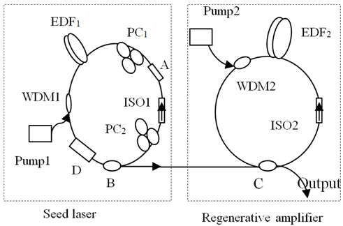
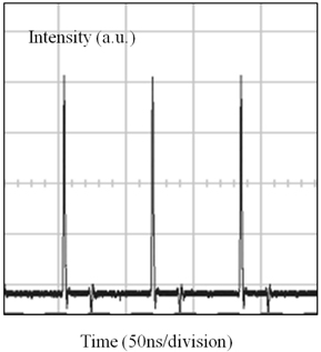
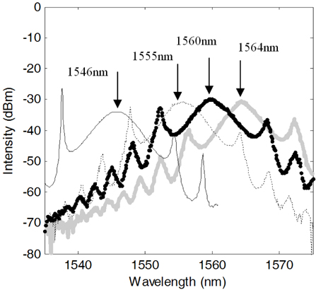
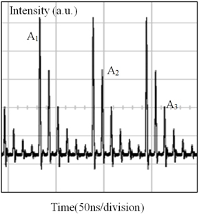
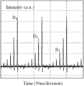
The system setup of the Er-doped regenerative fiber amplifier is shown in Fig. 1. A homemade mode-locked fiber laser based on the nonlinear polarization rotation (NPR) technique is adopted as the seed laser [17], as shown in the left part of the figure. The seed laser has a ring cavity and is pumped by a 980 nm laser diode. The gain media is Erbium doped fiber (LIEKKI Er80 8/125). The seed laser outputs pulses with a repetition rate of 15.3 MHz. The output optical spectrum of the seed laser can be tuned from 1546 nm to 1564 nm by adjusting the polarization controller in the laser cavity, as shown in Fig. 2. The seed laser is operated at the fundamental mode locking region with a single pulse output each round trip. The output pulses from the seed laser are fed into the regenerative amplifier, shown as the right part in Fig. 1 The pulses circulate in the fiber loop of the amplifier and are extracted by a 50% coupler. The length of EDF2 of the regenerative amplifier is 0.8m. The backward pump is adopted. The total length of the ring cavity of the amplifier is about 13m. If the length of the seed laser cannot be matched, the amplification cannot be realized. Fig. 3 shows the oscilloscope trace of a typical output pulse train of the seed laser detected by a 2 GHz photodetector. The small pulses accompanying the main pulses are due to the reflection caused by the photodetector. Figure 4 shows that the length of seed laser is 2 meter shorter than the length of the ring amplifier.The input of one pulse was analyzed as following. When one pulse A was fed into the regenerative amplifier, the pulse A1 was output first; the other part of the pulse A was amplified by the amplifier. When it circulates in the fiber loop of the amplifier, the pulses A2 and A3 were output in succession. Figure 5 shows that the length of the seed laser is 2 meter longer than the length of the ring amplifier. As the analysis of the above, when the pulse B was fed into the amplifier, the pulses B1, B2 and B3 were output in succession. The change of spacing between two adjacent pulses is about 10 ns, which corresponds to a delay generated by 2 m fiber. These waveform were measured when the total length of the ring cavity of amplifier remain unchanged. The output would be different under different matching conditions.
By analyzing the waveform, we can adjust the length of ring cavity of the regenerative amplifier. After getting the suitable fiber by adjusting the optical delay-line if the difference of the length is too close, the pulse amplification can be like that of Fig. 3 when the time has been matched. The repetition rate of signal pulse is 15.3 MHz. If the difference of the two ring cavity length is large, complicated pulses can be observed. This question will not appear for CW amplification with regenerative amplifiers. The adjustable range of optical delay-line is from 0 to 12 cm. The relative accuracy of time is 17 fs because the accuracy of adjustment is 5 μm. So it is easy to meet adjustment precision of 815 fs duration pulses trains amplification.
As we can see, the most important part in the amplification is to match the length between seed laser and regenerative amplifier. We first measure both two cavity lengths with a ruler to provide coarse adjustment. Then we adjust the optical delay-line while monitoring the trace on the oscilloscope to realize fine adjustment of the length. With this method, a good match can be obtained.
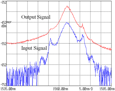
Figure 6 shows the spectrum of input and output signal pulse. When input signal power is -23.27 dBm and pump drive current is 122 mA, the spectrum width of input signal is 4 nm and the spectrum width of output signal is about the same as the input signal. The width of input pulse duration is about 815 fs. This pulse width of input pulses was measured by an autocorrelator directly from the mode-locked laser source. The pulse shape was confirmed to be a soliton. The pulse width of output pulses cannot be measured by the autocorrelator due to the low output power. Meanwhile, it can be seen that the power of the wing of the spectrum has been increased due to the existence of spontaneous emission. It should also be noted that the pump drive current is fixed at 122 mA (corresponding to a pump power of 35.5 mW) because further increase of pump power will lead to self-oscillation of the amplifier cavity.
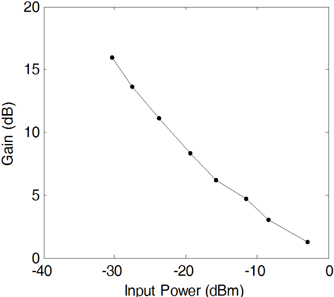
Figure 7 shows the output power change when the signal input power changes from -30.4 dBm to -2.9 dBm. Gain of 16 dB has been obtained when the signal power is -30.4 dBm and the pump power is 35.5 mW. In order to change the launching power, an adjustable attenuator was inserted between the coupler B and the coupler C. In fact, the gain decreases with increasing launching signal power owing to gain saturation effect.
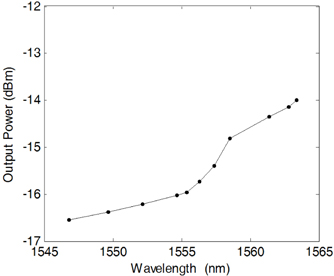
It is also observed that the output power of the amplifier varies with the center wavelength of the input pulse train. Figure 8 describes the output power change with the signal wavelength when launching signal power is -23.25 dBm. The pump drive current is also 122 mA. It was found that the output power increases when the signal wavelength changes from 1546.8 nm to 1563.4 nm.The gain of 1563.4 nm is about 2.5 dB higher than the gain of 1546.8 nm.The reason is the gain spectrum peak is about 1563 nm, the signal gain will be lower if the signal wavelength is far from the gain peak.
Considering that two connectors were adopted at the end of signal input and output in the experiment, with loss of about 2 dB, the actual gain would 2 dB higher than the measurement. In fact, the interval time of the adjacent input signal pulse was equal to the time when one pulse runs in the regenerative amplifier once in this experiment. But the output pulses will be interesting if the interval time of the adjacent input pulses is a multiple of the round trip time that a pulse travels in the regenerative loop.
In practical applications, however, the optical delay-line should insert in the ring fiber amplifier to amplify different repetition rate laser pulses although the optical delay-line will increase about 2 dB loss in the regenerative amplifier. As the next step, we will change the ratio of coupler and optimize the Er-doped fiber length in order to get higher gain or output power.
The pulses with 815 fs duration and 15.3 MHz repetition rate have been demonstrated to be amplified by a regenerative Er-doped fiber amplifier. This kind of regenerative amplifier runs under the threshold of self-lasing. A gain of 16 dB is realized at the power level of -30.4 dBm of input signals. It is also found that the performance of a regenerative amplifier for pulses is very different from that for CW signals. Pumping above a certain threshold can lead to self-oscillation in the amplifier. This kind of regenerative amplifier can easily achieve the high repetition rate pulse regenerative amplification relative to the other kind of regenerative amplifier that has an optical switch in the amplifier like ref 13-16. This type of regenerative amplifier technique can also be applied to the other rare-doped fiber amplifier systems such as Yb and Tm.