The compact laser transmitter, delivering an infrared (IR) light beam, has attracted considerable attention in a variety of applications, such as free-space optical communications, laser machining, laser-assisted welding and surgery, and a multiple integrated laser engagement system, which serves as a cost-effective military training system and makes extensive use of IR light beam transmitters to emulate a projectile [1-7]. For some long-range applications of the transmitter, the generated beam must travel hundreds of meters while maintaining a constant effective detectable width, which hinges upon a predefined threshold intensity level associated with a receiver [8-10]. However, previous approaches mostly focused on the alignment of the IR beam with the launching apparatus, by virtue of a visible monitoring beam used to track the main IR beam [11-13]. The conventional approaches inevitably suffer from the undesirable pseudo-miss issues caused by severe variations in the effective detectable width, which are seen particularly in the vicinity of the transmitter. In this paper, a portable, lightweight IR laser transmitter featuring a highly uniform detectable beam width has been proposed and constructed, incorporating a flexible beam shaper that is composed of a perforated diffuser sheet and a pinhole, considering that a diffusing element may be potentially useful in facilitating beam formation [14-16]. The intensity profile of the generated IR beam was practically observed in an outdoor feasibility test, and the detectable beam width for a given threshold level was confirmed to be satisfactorily uniform, both theoretically and experimentally.
II. PROPOSED UNIFORM BEAM TRANSMITTER AND ITS DESIGN
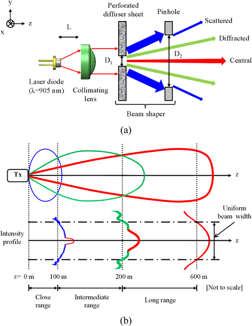
The aim of this work was to develop a miniature IR beam transmitter that delivers a highly uniform detectable width throughout an operation range beyond 600 m. As schematically illustrated in Fig. 1(a), the proposed transmitter consists of a laser diode (LD) as the light source, a collimating aspheric lens, and a beam shaper, which takes advantage of a perforated diffuser sheet in conjunction with a pinhole serving as a spatial limiter. The IR beam emitted by the LD is initially collimated by the lens to impinge upon the beam shaper, which appropriately tailors the profile of the incoming collimated elliptical beam. Figure 1(b) shows the contours of intensity distributions for the scattered, diffracted, and central beams with respect to a given threshold detection level. Three of the representative intensity profiles belonging to the particular uniform IR beam are also shown in Fig. 1(b), in the close, intermediate, and long ranges. The detailed process to obtain a highly uniform IR beam can be described as follows. First, part of the incoming beam passing through the aperture of the perforated sheet diffuser produces a strong Gaussian-like circular beam, which is loaded with weak side lobes of Fraunhofer diffraction patterns around the edge. As shown in Fig. 1(b), for a given threshold detection level the welldefined central beam is anticipated to generate inherently a progressively increasing effective beam trajectory, in the course of traveling in the close and intermediate ranges from about z=0 to 100 m and 100 to 200 m, respectively. However, it is predicted that, as a result of the gradual spreading of the Gaussian-like main beam, a fairly uniform trajectory can still be obtained in the long range from z=200 to 600 m. Second, the ring-shaped side lobes surrounding the central beam, which are attributed to the slight diffraction mediated by the aperture of the perforated diffuser, are added to the main central beam in the intermediate range, so that the corresponding detectable beam width can become equivalent to that of the long range. Third, the outermost portion of the incident collimated light has been deliberately scattered via the sheet diffuser to generate a drastically diverging beam in the close range, leading to an enlarged uniform beam width comparable to that of the intermediate and long ranges. Accordingly, the blind spot in the immediate vicinity of the transmitter has been almost eliminated. It should be stated that a pinhole was specifically introduced as a spatial limiter alongside the perforated diffuser sheet, with the aim of preventing the scattered light from excessively broadening the beam. Consequently, as implied from the beam-forming process described in Fig. 1(b), the proposed beam shaper was regarded as playing a pivotal role in adaptively modifying the incident collimated beam, rendering the IR beam with a noticeably uniform detectable width over a long distance.
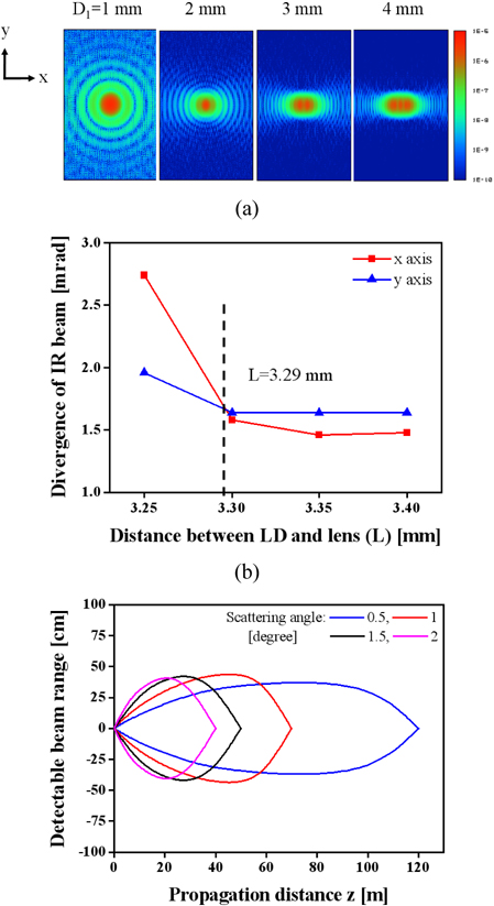
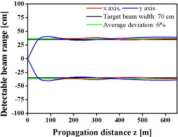
The uniform IR transmitter was designed and analyzed with the simulation tool ZEMAX from Radiant Zemax. An LD at λ=905 nm, emitting an IR beam with divergence angles of 23.8 and 6.8 degrees along the x and y axes respectively, was primarily taken into account. We first determined the aperture size (D1) of the perforated diffuser sheet, considering that the aperture influences the formation of the ring-like side lobes that reside outside the central beam. In the intermediate range the intensity profile of the beam, exhibiting the Fraunhofer diffraction pattern [17, 18], was inspected at z=200 m from the transmitter while D1 was varied from 1 to 4 mm at 1 mm intervals, as shown in Fig. 2(a). In order to realize widths that are as equivalent as possible along both x and y axes, the ring patterns associated with the side lobes were intended to be symmetric, which was optimally satisfied for the case of D1=1 mm. It is noted that the beam size at long range is fundamentally dependent upon the divergence angle, which is determined by the distance L between the LD and collimating lens. As plotted in Fig. 2(b), we thus examined the divergence angle in terms of the distance L, searching for the optimum value of L that leads to equal divergence along the two axes. The divergence angles were discovered to be approximately the same at 1.7 mrad for L=3.29 mm. After dealing with the beam at the long and intermediate ranges, we investigated the beam profile at close range, considering a beam shaper drawing upon a sheet diffuser linked with a pinhole acting as spatial limiter. As shown in Fig. 2(c), the effective trajectory, exhibiting the detectable width of the scattered beam from the diffuser along the propagation direction, was observed when the scattering angle of the diffuser sheet changed from 0.5 to 2 degrees. In order to efficiently cover the close range, the diffuser sheet was set to have a scattering of 0.5 degrees. With a view to ensuring that the diffused beam would not be unacceptably expanded in the close range, the pinhole was chosen to have a diameter of D2=1.6 mm. As presented in Fig. 3, the transmitter was devised to yield a constant detectable beam width of 70 cm for an optical intensity threshold level of 10-8 W/mm2 , entailing an average deviation of as little as 6%. The detectable beam width was observed to remain highly constant over the operational distance of 600 m.
III. DEVICE FABRICATION AND EXPERIMENTAL RESULTS
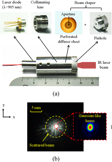
The small IR beam transmitter was manufactured via a cost-effective assembly process, as described in Fig. 4(a). An aluminum tube was used to accommodate a collimating lens as well as a perforated holographic diffuser sheet (Model #65-883 from Edmund Optics) with a mechanically drilled aperture. The diffuser sheet has a scattering angle of 0.5 degrees, a transmission efficiency of 90%, and a thickness of 0.73 mm. The LD was then precisely aligned with the lens as well as the diffuser sheet. A pinhole acting as a cover was inserted into the tube from the front face, in order to secure the diffuser sheet. For the assembled IR transmitter, which is merely 4.7 cm long, the beam profile was first monitored at a position of z=1 m, as depicted in Fig. 4(b). The bright circular spot at the center was revealed to represent a Gaussian-like beam, whose divergence angles were approximately 2 and 2.2 mrad along the x and y axes, respectively. The central beam was observed to be surrounded by a scattered beam. The slope efficiency for the generated IR beam, defined as the ratio of the output optical power of the transmitter to the applied drive current, was found to be 0.39 mW/mA, The demonstrated slope efficiency translates into an optical coupling efficiency of 36%, which is in good agreement with the calculated efficiency of ~38%.
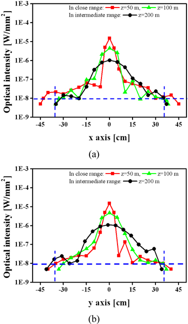
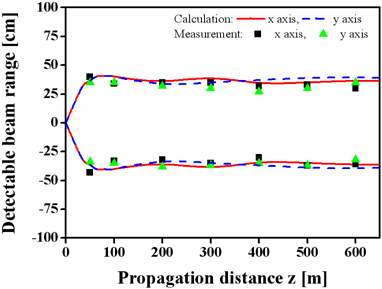
In an outdoor feasibility test, the manufactured IR light transmitter was chiefly evaluated with respect to the evolution of the intensity distribution of the generated IR beams, and the resulting effective detectable beam widths. The transmitter was initially driven by a pulse signal with a repetition rate of ~3 kHz, and the output pulsed light was detected with an energy sensor (Model PD 10-Pj from OPHIR), thereby mapping the optical intensity profile at several locations along the propagation direction. In order to verify the effect of the proposed beam shaper in the close and intermediate ranges, the intensity profiles were scrutinized at z=50, 100, and 200 m along the x and y axes, as plotted in Figs. 5(a) and (b), respectively. The IR beam was observed to be successfully expanded to a nearly constant width of ~70 cm, due to the scattered light produced by the sheet diffuser as well as the diffractioninduced side lobes resembling ring patterns. For a receiver with a threshold intensity level of 10-8 W/mm2, the corresponding detectable beam width was readily estimated for the entire travel distance, ranging up to 600 m. Figure 6 shows the measured and calculated trajectories that are made up of the detectable beam width as a function of the propagation distance. As a whole, the effective beam width was stably maintained at 70 cm along the two axes, exhibiting a substantially uniform circular cross-section of ~70 cm in diameter. The achieved width may be suitable to cover a human body, as might be targeted by a projectile in a typical simulated engagement system. The IR beam width slightly fluctuated within about 4 cm, translating into a small deviation of 6% on average. It should be mentioned that good agreement between the theoretical and experimental results was clearly attained, as presented in Fig. 6.
In summary, a miniature IR laser transmitter featuring a highly uniform detectable beam width was constructed by taking advantage of flexible beam forming, which is made possible by a perforated holographic diffuser sheet integrated with a pinhole acting as a spatial limiter. The beam shaper was used to tailor the incoming light flexibly via both scattering and diffraction, to equalize the effective beam width over a long distance. By monitoring the optical intensity profile of the generated IR beam over a long distance, the realized transmitter was validated to provide a remarkably uniform effective beam width of 70 cm, with a small average deviation of 6% throughout an effective range of 600 m. In order to extend the propagation range, we will develop a laser transmitter incorporating a high-power laser source such as pulsed LDs, taking into consideration its power level and beam profile. A beam shaper based on multiple diffuser sheets will be also attempted to more delicately tailor the output beam profile.