합성가스를 생산하기 위한 부분산화, 이산화탄소 리포밍, 메탄에 의한 산화CO2 리포밍 공정들은 니켈 하이드로탈사이트(Ni0.5Ca2.5Al) 촉매를 이용하여 수행되었고 안정한 이중층 구조를 형성시키기 위한 금속지지체(Mg, Ca)의 영향에 대해서도 다양한 연구가 진행되었다. 지지체전구물질(Mg, Ca)에 따라 메탄 리포밍의 안정성은 활성니켈이온과 지지체금속이온 사이의 결합강도차이에 의해 영향을 받는다. Ni-Mg-Al 구성체는 가장 안정한 하이드로탈사이트 이중층 구조이지만 Ni-Ca-Al 구성체는 그렇지 않다. 이산화탄소 리포밍 장기테스트에서 Ni-Mg-Al 촉매는 약 100시간 동안 80%의 효율을 유지하면서 탁월한 안정성을 보였지만 Ni-Ca-Al 촉매는 반응초기에 불활성화됨을 확인할 수 있었다. 활성금속 Ni과 지지체 Mg-Al 사이의 결합강도를 확인하기 위해 승온 환원(temperature-programmed reduction, TPR) 분석을 시행하였다. 이를 통해 Ni-Mg-Al 촉매가 Ni-Ca-Al 촉매보다 Ni의 환원온도가 더 높음을 확인할 수 있었다. Ni0.5Ca2.5Al 촉매는 가장 높은 초기반응성을 보였지만 코크형성으로 인해 반응성이 빠르게 감소하였다. 결론적으로 Ni0.5Ca2.5Al 촉매가 코크형성에 대한 강한 저항성을 갖고 있기 때문에 다른 촉매들보다 높은 반응성과 안정성을 갖는 것으로 보여진다.
In recent years, the replacement of fossil fuels has received much attention as a result of various environmental issues as well as the limited amount of resources[1]. Therefore, the utilization of natural gas (mainly CH4) for useful energy applications in transportation, such as methanol, hydrogen, or synthesis gas, is an attractive technology. There are many approaches to develop of highly resistant catalysts for the CH4 reforming process and improve simultaneously the lifetime of the catalysts. One of the most common active metal components is Ni supported by stable materials (i.e.; Al2O3). Supported Ni catalysts are the typical choice for methane reforming, with Ni metal being an active component in CH4 dissociation[2-4]. Typically, supported Ni catalysts are prepared by the wet-impregnation method. However, the catalysts prepared by wet-impregnation are often not fully capable of reduction by H2 and the active Ni metal is often not homogenously distributed on/in the catalyst [5]. Additionally, Ni particles typically sinter during reformation reactions at high temperatures[6], and the larger Ni particle sizes promote carbon formation. Under reforming conditions, catalyst deactivation also leads to a reduction in pressure due to the build-up of carbonaceous species[4,7,8]. A catalyst with a homogeneously distributed active sites would therefore be more resistant to sintering and coke formation under extreme conditions[9-12]. Hydrotalcite (HT)-like compounds, a class of layered double hydroxides (LDHs), contain 2+ and 3+ metal ions randomly distributed throughout the layered structure. The Mg-Al HT precursors, based on [Mg1-x2+Alx3+(OH)2]x+(CO3-x)⋅
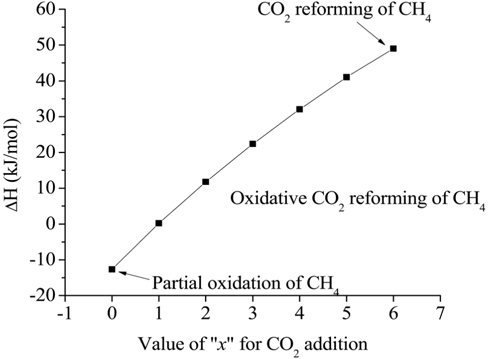
Eq. (1) represents the general expression of the combined partial oxidation reaction where CO2 reforming is converted to CH4, where x represents the amount of CO2 added. The stoichiometric amount of oxygen can then be determined by the amount of CO2 present. If


As described above, a variety of catalysts have been previously employed in steam reforming, partial oxidation, and dry reforming to produce synthesis gas. However, most of these studies did not include long-term experiments to determine the stability of the HT-type catalyst. In this study, a typical Ni-Mg/Al HT-type catalyst was used for synthesis gas production. Additionally, the effects of various cations on the formation of the HT-type catalyst were evaluated with respect to stability.
Two co-precipitated catalysts (Ni0.5Mg2.5Al and Ni0.5Ca2.5Al) were prepared. The preparation procedure for both catalysts was identical, with either Mg or Ca nitrates being used as the precursors. For the preparation of the Ni0.5Mg2.5Al catalyst, 30 mL of a 1 M Ni nitrate (Ni(NO3)2⋅6H2O, Puratronic®, 99.9985%) aqueous solution, 150 mL of a 1 M Mg nitrate (magnesium nitrate hexahydrate, Alpha-Aesar, ACS grade 98.0-102.0%) aqueous solution and 60 mL of a 1 M Al nitrate (Al(NO3)3⋅9H2O, Alpha-Aesar, ACS grade 98.0-102.0%) aqueous solution were prepared and mixed. The mixed nitrate solution was then added drop-wise into 240 mL of a 0.50 M Na2CO3 aqueous solution at room temperature under vigorous stirring (400 rpm). A 3.0 M NaOH aqueous solution was simultaneously added drop-wise to maintain the pH at 10.0±0.1. The resulting precipitate was aged in the mother liquor at 120 ℃ for 12 h. The aged precipitate was then cooled to room temperature and held for 1 h. The precipitate was then washed and filtered with distilled and de-ionized water until the residual Na+ in the aged precipitate was removed (pH -7). The washed precipitate was then dried at 120 ℃ for 12 h. The Ni0.5Ca2.5Al catalyst was prepared in the same manner using a mixture of 30 mL of 1 M Ni nitrate, 150 mL of 1 M Ca nitrate (Ca(NO3)2⋅4H2O, Alpha-Aesar, ACS grade 98.0-102.0%), and 60 mL of 1 M Al nitrate. In preparing the 10 wt% Ni/Al2O3 catalyst, -75 mL of distilled water was heated to 80 ℃ while stirring, and γ-Al2O3 powder (Alpha-Aesar, 99.97% (metal basis)) was then added to the distilled water. 1 M Ni nitrate was added drop-wise, until the target 10 wt% of Ni relative to the Al2O3 was obtained. For all catalysts, water was evaporated under continuous stirring at 80 ℃. The resulting residue was then heated in an oven at 120 ℃ for 12 h, and the dried precipitate was crushed to powder form. The powder precipitates were calcined at 850 ℃ in air for 5 h to produce an oxide-phase catalyst. The calcined catalysts were pelletized to attain a particle size of 354-500 µm.
2.2. Catalyst characterization
The catalyst crystal structures of the fresh and spent catalysts were characterized using X-ray diffraction (XRD). Powder XRD patterns were measured on a Rigaku D/Max-III C using standard Bragg-Brentano geometry with Ni-filtered Cu Kα radiation (λ1 =1.5406 Å, λ2 =1.5444 Å) and 40 kV/100 mA X-ray radiation. The XRD data were collected in the range of 5° to 80° 2θ range using a step size of 0.01 and a count time of 1s. The diffraction patterns were identified upon comparison with spectra in the JCPDS data base (International Centre for Diffraction Data, USA). Catalyst surface areas were measured using a Micromeritics Gemini 3 2375. Approximately 100 mg of the pelletized catalysts (particle size in the range 354-500 µm) was loaded and the surface area was measured at -196 ℃, using liquid nitrogen as the adsorbate. Eleven points within the P/P0 range of 0.05 and 0.3 were collected and used to produce the BET plot and subsequently calculate the surface area. The BET surface areas of the Ni0.5Mg2.5Al, Ni0.5Ca2.5Al, and Ni/Al2O3 catalysts after calcination and reduction are listed in Table 1 and compared to some reference values. After reduction in 10% H2/N2 at 720 ℃ for 1 h, the surface areas increased, which implied re-construction of the catalyst surfaces. The Ni0.5Ca2.5Al catalyst had the highest increase in surface area after reduction.
[Table 1.] Catalyst surface areas after calcimation and reduction
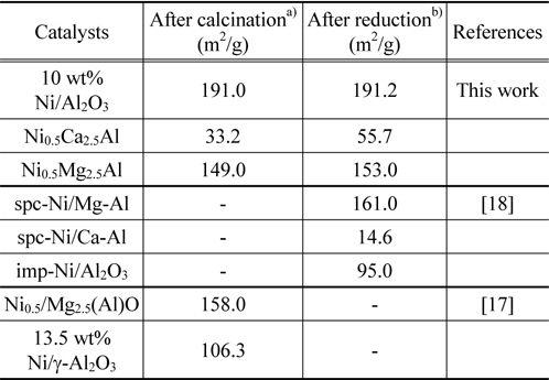
Catalyst surface areas after calcimation and reduction
The catalyst morphology was examined using scanning electron microscopy (SEM). A Leo FESEM 1530 SEM was utilized in this investigation, and the vacuum pressure was less than 1.5 ×10⁻⁵ mbar. TPR and TPO were also used to characterize the catalysts. For the TPR test, 100 mg of the calcined catalyst was placed in a quartz tube and the temperature was ramped at 10 ℃/min from 25 to 800 ℃ in the presence of a 10% H2/N2 reducing gas mixture flowing at 30 mL/min. A thermal conductivity detector (TCD) was then used to measure the amount of H2 consumption. The amount of coke produced during the CO2 reforming of CH4 was determined by TPO in a Hiden Catlab micro-reactor system. 25 mg of the spent catalyst was placed in the quartz tube and a 30 mL/min 10% O2/He gas mixture was utilized. The sample temperature was increased from 25 ℃ to 850 at 10 ℃/min.
A fixed-bed reactor was designed to examine the catalyst performances. The catalyst bed resided in a 10 mm I.D. quartz tube with a highly porous quartz frit to support the catalyst. A thermocouple located at the top of the catalyst bed was used to control the furnace temperature. Before the reaction tests, the effects of the external and internal mass transfer limitation at a constant GHSV of 240,000 cm3/g-h were examined. For the external mass transfer, a fixed residence time (W/F=0.015) through a variety of feed velocities (50, 100, 150, 200 and 250 mL/min of total feed) at 700 ℃ was chosen. The internal mass transfer was evaluated using a feed mixture composed of CH4/ CO2/N2 =1/1/3 at 700 ℃ for various sizes of catalysts (average 303, 427, and 605 μm). When the CH4 consumption rate was unchanged for the external and internal mass transfer limitations, the reaction can then be controlled by the reaction limitation instead of the diffusion limitation. The activation energy of CH4 and CO2 consumption was determined by the Arrhenius plot. For each reaction test, 50 mg of the calcined catalyst with a particle size between 354-500 µm was diluted with 400 mg of SiC (422-599 µm). The SiC was used to prevent an increase in pressure due to coke formation and subsequently improve the thermal dispersion throughout the catalyst bed. The catalysts were reduced

The resulting gases were collected and sampled using a gas chromatography (GC) column (Varian CP-3800 with a Carboxen-1000) to quantify the components of the product gases. The CH4 conversion rate (Eq. (5)) and the synthesis gas ratio, H2/ CO, (Eq. (6)) were calculated from the concentrations measured by GC, which were then converted into molar flow rates. The activation energy of CH4 and CO2 were calculated from the Arrhenius plot (Eq. (7)).


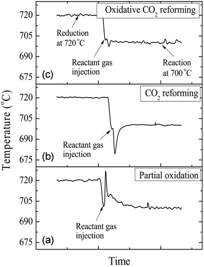
For the pre-treatment, the catalysts were reduced at 720 ℃ in 10% H2/N2 for 1 h. The three reactions-partial oxidation, CO2 reforming, and oxidative CO2 reforming of CH4-were carried out with a GHSV=240,000 cm3/g-h at 700 ℃ for 20 h during the first set of experiments.
3.1.1. External and internal mass transfer limitation
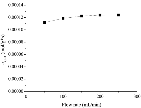
Reliable kinetic data could be obtained when the mass transfer limitation (external and internal) was negligible. The effects of the feed flow rate and catalyst particle size on the reaction rate were experimentally determined using a feed mixture composed of CH4/CO2/N2 (1/1/3) at 700 ℃. For the external diffusion, a constant rate (W/F=0.015 g*s/mL) was applied in order to maintain the amount of contact time. The effects of the flow rate with a consistent amount of contact time are shown in Figure 1. It is clear that the rate of CH4 consumption increased until the flow rate was 200 mL/min. This result indicated that up to the flow rate of 200 mL/min, the external mass transfer had some influence on the overall reaction rate. However, when the flow rate exceeded 200 mL/min, the rate of CH4 consumption remained constant. Therefore, experiments with a flow rate of 200 mL/min are adequate to obtain reaction data that are not masked by the external transport limitation.
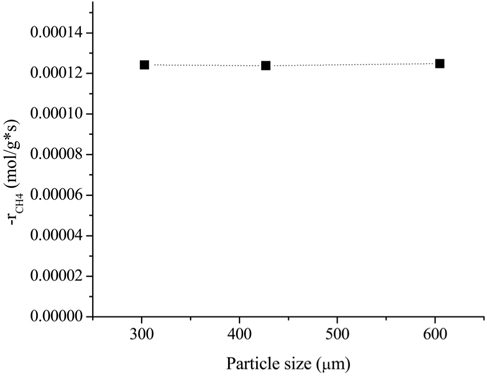
In order to investigate the possible effects of internal diffusion limitation, three different particle sizes were tested: (i) 251-354 μm (average 303 μm), (ii) 354-500 μm (average 427 μm), and (iii) 500-710 μm (average 605 μm). The flow rate was chosen to be 200 mL/min based on the external limitation. The effects of the particle size on the rate of CH4 consumption is shown in Figure 2. It was clear that the rate of CH4 consumption was independent of the average diameter of the particles. This result indicated that particle sizes between 250 and 700 μm are small enough for the reaction to not be affected by internal mass limitation at 700 ℃.
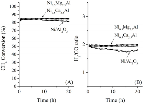
3.1.2. Partial oxidation of CH4
The conversions attained during the CH4 partial oxidation and the resulting synthesis gas ratios (H2/CO) are shown in Figure 3. All catalysts exhibited -85% CH4 conversion and the Mg- and Ca-containing samples exhibited no significant deactivation over the 20 h test. Additionally, the levels of reactivity were all determined to be near the equilibrium levels. The Ni/Al2O3 catalyst exhibited some deactivation beginning after 13 h of reaction, which confirmed that the Ni/Al2O3 catalyst deactivates over time, as confirmed by many other previous studies[21-23]. The synthesis gas ratios (H2/CO ratio) obtained with each catalyst exhibited similar patterns. The Ni0.5Mg2.5Al and Ni0.5Ca2.5Al catalysts resulted in a syngas ratio of around 2, close to the theoretical level. This result indicated that since H2 and CO were produced in proportion, the stoichiometry in Eq. (4) was applied and neither product was preferentially consumed via side reactions afterwards. The syngas ratio decreased with time over the Ni/Al2O3 catalyst, which corresponded to the reduced conversion. In conclusion, for the partial oxidation of CH4, the two co-precipitated catalysts (Ni0.5Mg2.5Al and Ni0.5Ca2.5Al) exhibited stable reactivity for 20 h of reaction with conversions close to the equilibrium level and syngas ratios near the predicted values based on the reaction stoichiometry.
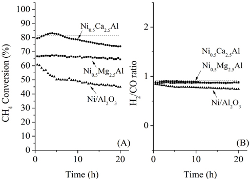
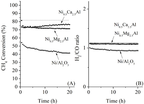
Coke covering the active Ni sites will ultimately lower the activity of the catalyst. It is therefore assumed that the dry reforming is a good indicator of the carbon deposition resistance of a given catalyst. Under CO2 reforming of CH4, two reactions typically occur CO2 reforming of CH4 (Eq. (3)) and the reversible water-gas shift (RWGS) reaction (Eq. (8)). Therefore, in addition to the main reaction, the RWGS also affects the overall pathway. For example, due to the RWGS reaction, the syngas ratio (H2/CO) for CO2 reforming of CH4 was always less than 1.

The CH4 conversions at 700 ℃ for the three catalysts, along with the equilibrium conversion, are shown in Figure 4. At 700 ℃, the theoretical CH4 conversion level was -82%. The CH4 conversion using the Ni0.5Ca2.5Al catalyst increased slightly at the beginning and reached the equilibrium CH4 conversion (82%) within 4 h time-on-stream. However, after 4 h it slowly deactivated over time, decreasing from 82% to 75% after 20 h. This reduction was likely caused by carbon build-up on the surface, which was confirmed by TPO and will be discussed later. The Ni/Al2O3 catalyst exhibited continuous deactivation from an initial CH4 conversion of 60%, decreasing to 48% conversion after 20 h. It is important to note that Ni/Al2O3 also had the lowest initial CH4 conversion. Alternatively, the Ni0.5Mg2.5Al catalyst exhibited very stable conversion (-68%) compared to the other catalysts. This result indicates that the Ni0.5Mg2.5Al catalyst exhibited the highest resistance to deactivation. However, the conversion was lower than the equilibrium conversion, and lower than the conversion obtained with the Ca-containing catalyst. The syngas ratios (H2/CO ratios) were also less than unity due to the reverse watergas shift (RWGS) reaction (Eq. (8)). Additionally, even though the CH4 conversion over the three catalysts was distinguishable, the syngas ratios were very similar and all catalysts started with a ratio of -0.9, which was close to the equilibrium value. These results confirmed that the CH4 conversions were dependent on the catalysts, but the synthesis gas ratios were not, which suggested that the same reaction pathway was occurring over each catalyst. These results also indicated that the RWGS reaction rapidly reaches equilibrium for CO2 reforming of CH4 at 700 ℃.
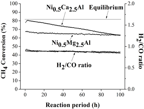
During 20 h of time-on-stream, the Ni0.5Mg2.5Al catalyst exhibited high stability, and the Ni0.5Ca2.5Al catalyst exhibited deactivation. However, even after 20 h, the activity of the Cabased catalyst was still higher than the Mg-based catalyst. It is therefore difficult to conclude after 20 h time-on-stream which of these two catalysts was better. Therefore, more prolonged experiments were performed at 100 h time-on-stream for these two catalysts. The pre-treatment processes were identical to those described previously. The experimental results for the Ni0.5Mg2.5Al catalyst and the Ni0.5Ca2.5Al catalyst are shown in Figure 5 for over 100 h of the dry reforming. The Ni0.5Mg2.5Al catalyst exhibited a relatively stable reactivity based on the CH4 convertsion and the H2/CO ratio. The CH4 conversion decreased by about 4% over 100 h, from 67 to 63%. However, for the Ni0.5Ca2.5Al catalyst, the deactivation trend observed during the first 20 h continued throughout 100 h. The CH4 conversion decreased from 78 to 62% but the syngas ratio only slightly decreased. Based on these longer-term experiments, it was clear that the Ni0.5Mg2.5Al catalyst suffered considerably less deactivation than the Ni0.5Ca2.5Al catalyst and exhibited a much higher resistance to coke formation, as will be discussed below. In conclusion, the Ni0.5Mg2.5Al catalyst exhibited the highest stability, even though the activity remained lower than the equilibrium-based expectation. The Ni0.5Ca2.5Al catalyst initially exhibited the highest activity, reaching equilibrium after about 4 h time-onstream, but past 4 h its activity continuously decreased at a rate of -0.2%/h. Finally, the Ni/Al2O3 catalyst exhibited the worst reactivity and stability for the dry reforming.
3.1.4. Oxidative CO2 reforming of CH4
The basic concept of the oxidative CO2 reforming of CH4 is to combine the exothermic partial oxidation with the endothermic CO2 reforming. The change in reaction enthalpy (ΔH) at 700 ℃ for the range of x [Eq. (1)] between 0 and 6 was simulated using ASPEN PlusTM, the results of which are shown in Figure 6. When x was 0, Eq. (1) represented the partial oxidation of the CH4 reaction and when
The catalytic activities for the oxidative CO2 reforming of CH4over the three catalysts are shown in Figure 8. Co-feeding O2 with CH4and CO2 was expected to reduce carbon deposition as a result of the increased oxidation of surface carbon species and also increase the conversion of CH4at high temperatures (-700 ℃). The reactivities of the Ni0.5Ca2.5Al and Ni0.5Mg2.5Al catalysts during the initial period (< 5 h) were similar (-75%). The reactivity of the Ni0.5Ca2.5Al catalyst for oxidative CO2 reforming of CH4was less than that of CO2 reforming of CH4; however, the reactivity of the Ni0.5Mg2.5Al catalyst was quite similar. Since the feed for the oxidative CO2 reforming of CH4contains oxygen that might oxidize surface carbon, the Ni0.5Ca2.5Al catalyst did not exhibit deactivation, and conversion actually slightly increased after 20 h of reaction. The syngas ratios for the catalysts were similar, even though the syngas ratio for the Ni/Al2O3 was slightly lower than that of the other catalysts. These trends (different conversions but same syngas ratios) were also observed in the partial oxidation and CO2 reforming reactions, which suggested that the same reaction mechanisms existed over the three sample types. Additionally, except for the Ni/Al2O3 catalyst, the H2/CO ratio was very close to its equilibrium value, which implied that the RWGS reaction reached equilibrium in the presence of the Ni0.5Mg2.5Al and Ni0.5Ca2.5Al catalysts at 700 ℃.
Overall, based on the reactivity tests for all three sets of reactions, the Ni0.5Mg2.5Al catalyst exhibited the most stable reactivity among other catalysts under the most severe conditions (e.g. CO2 reforming of CH4). Additionally, the reactivity of the Ni0.5Mg2.5Al catalyst, although lower than the equilibrium conversion, still resulted in greater than 70% CH4 conversion. The Ni0.5Ca2.5Al catalyst exhibited the highest initial CH4 conversion for all reactions; however, its reactivity began to degrade shortly after the onset of the dry reforming test. Finally, as expected, the tests on oxidative CO2 reforming of CH4 exhibited convertsions between those of the partial oxidation and the dry reforming. An important difference between the oxidative CO2 reforming and dry reforming in the presence of the Ni0.5Ca2.5Al catalyst was that the reactivity was more active when oxygen was added and its activity decreased initially but eventually stabilized at a level similar to that of Ni0.5Mg2.5Al. Nonetheless, the Ni0.5Mg2.5Al catalyst exhibited superior stability under dry reforming and oxidative reforming.
3.1.5. Activation Energy and Effects of the Partial Pressures of CH4, CO2, and H2
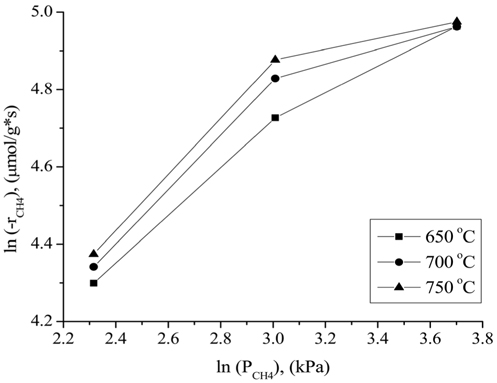
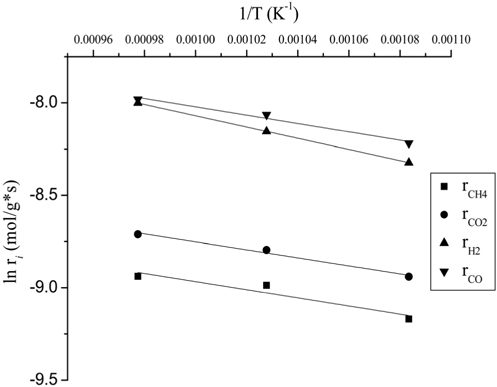
Typically, the kinetic studies were conducted at the temperature in which the conversion was far from the equilibrium. It was confirmed that the CH4 consumption rate from the reactivity test (Figure 4) at 700 ℃ was lower than the equilibrium level. The temperature sensitivity of the CH4 consumption rate for CO2 reforming of CH4 over the Ni0.5Mg2.5Al-HT catalyst was determined by the Arrhenius plot (Figure 9) in the temperature range of 650-750 ℃ at a constant GHSV of 240,000 cm3/g-h. It was clear that the support of Ni crystallites significantly influenced the activation energy by affecting the rate-controlling step in the reaction sequence. The activation energy for the consumption of CH4 and CO2 and the formation of H2 and CO on the Ni0.5Mg2.5Al-HT catalyst were calculated to be 18.9, 18.0, 25.3, and 18.7 kJ/mol, respectively. Based on the present investigation, it was determined that the rate determining step of CO formation closely corresponds to the CH4 and CO2 consumption step. One possible reason for obtaining a high energy barrier for H2 formation was the RWGS process. Since the activation energy barrier of the CH4 consumption step was slightly greater than that of the CO2 consumption step, it was assumed that the CH4 dissociation step could be the rate determining step. The lower activation energy barrier for CO2 consumption might be caused by the presence of the strong Lewis base MgO, which can facilitate the activation of CO2.
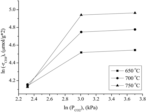
The influence of the partial pressures of CH4, CO2, and H2 on the Ni0.5Mg2.5Al-HT catalyst at atmospheric pressure for the CH4 consumption rate (-rCH4) was evaluated in the temperature range of 650-750 ℃. A constant CO2 (or CH4) partial pressure of 20.26 kPa was used as the CH4 (or CO2) partial pressure was varied. N2 gas was used to balance the total GHSV to 240,000 cm3/g-h for all conditions. As shown in Figure 10, the CH4 consumption rate was strongly affected by the partial pressure of CH4 at a CO2 partial pressure of 20.26 kPa, since the CH4 consumption rate increased as the CH4 partial pressure increased. As shown in Figure 11, the CH4 consumption rate was strongly influenced when the partial pressure of CO2 was lower (in the range of 10.13 to 20.26 kPa) than the stoichiometric ratio. The CH4 consumption rate was then unchanged at higher CO2 partial pressures (≫20.26 kPa). Therefore, it can be concluded that the reaction rate was more sensitive to the CO2 partial pressure than to the CH4 partial pressure when compared in the low partial pressure ranges (10.13 to 20.267 kPa). However, at high CO2 and CH4 partial pressures (≫20.26 kPa), the CH4 partial pressure exhibited a stronger influence on the CH4 consumption rates than
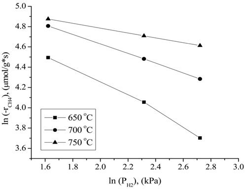
the CO2 partial pressure. These results can be attributed to the stronger adsorption of CH4 to the surface of the catalyst compared to that of CO2 at higher partial pressures. Figure 12 displays the rates of CH4 consumption at various partial pressures of H2 at constant CH4 and CO2 partial pressures of 10.13 kPa. As the H2 partial pressure increased, the rate of CH4 consumption decreased because the reverse reaction and RWGS reaction then become dominant.
3.2. Catalyst characterization
3.2.1. Structure of fresh and spent catalysts
The fresh Ni0.5Mg2.5Al and Ni0.5Ca2.5Al catalyst crystal structures were investigated using XRD, and all diffraction patterns were matched with JPCDS references. The XRD patterns obtained from the Ni0.5Mg2.5Al sample (Figure 13) confirmed that the as-prepared samples contained a well-crystallized HT-type (or LDH) phase. The LDH structure for the Ni0.5Mg2.5Al catalyst implied that Ni2++ was incorporated in the Mg2+ site positions and dispersed uniformly throughout the brucite layer of the HT structure. In particular, a set of three reflection peaks at 2
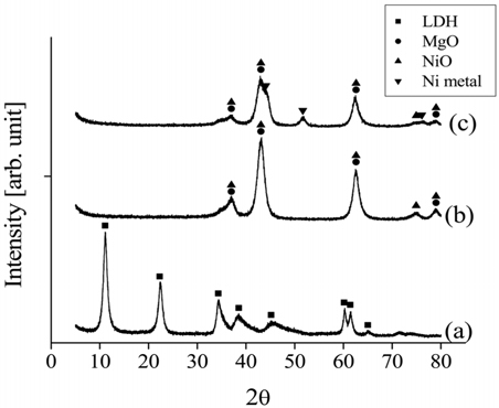
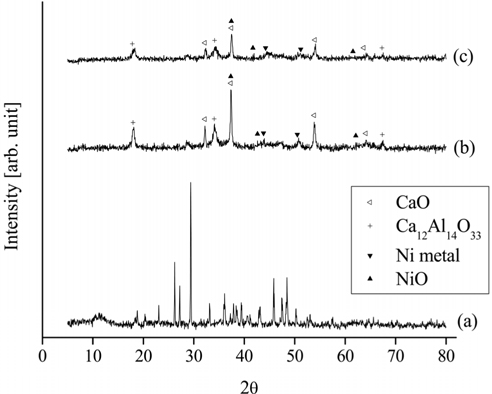
For the Ni0.5Ca2.5Al catalyst, the XRD patterns of the fresh, calcined, and reduced catalysts are shown in Figure 14. The fresh Ni0.5Ca2.5Al catalyst did not exhibit the HT-like structure. However, after being calcined at 820 ℃ in air for 5 h, NiO, CaO, and Ca12Al14O33 peaks appeared. Interestingly, Ni metal peaks were observed with the calcined Ni0.5Ca2.5Al catalyst but not with the Ni0.5Mg2.5Al catalyst, which implied that the Ni-Ca interaction was weaker than Ni-Mg interaction.
The XRD patterns of the spent Ni0.5Mg2.6Al catalysts after 20 h of partial oxidation, CO2 reforming and the oxidative CO2 reforming of CH4 at 700 ℃ are shown in Figure 15. Both Ni metal and NiO phases were observed after CH4 partial oxidation and the oxidative CO2 reforming of CH4. The oxygen species supplied for the partial oxidation of CH4 and the oxidative CO2 reforming of CH4 likely oxidized some of the Ni. However, the H2 or CO generated from the reactions can simultaneously reduce the formed NiO, subsequently regenerating the active Ni phases for further reactions, resulting in evidence of both chemical states being present. Additionally, a weak graphite peak was observed at 26.4° after CO2 reforming of CH4 and the oxidative CO2 reforming of CH4 tests, but not after the CH4 partial oxidation. The likely reason for its absence during partial oxidation is that the C:O ratio was the lowest (26:28) compared to the other two processes.
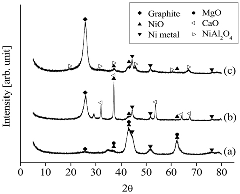
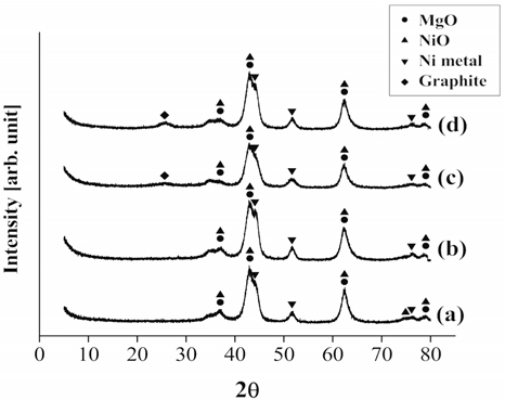
The XRD patterns of the different catalysts after 20 h of CO2 reforming of CH4 at 700 ℃ are shown in Figure 16. The diffraction patterns of Ni0.5Mg2.5Al indicated the presence of both metal and oxide Ni, as well as MgO. However, the XRD data obtained from the Ni0.5Ca2.5Al exhibited weaker Ni peaks, with significantly less Ni metal being observed. Most importantly, much stronger graphite peaks were observed on the Ni0.5Ca2.5Al and Ni/Al2O3 catalysts than on the Ni0.5Mg2.5Al catalyst. These results implied that the Ni0.5Mg2.5Al catalyst had a stronger resistance to coke formation.
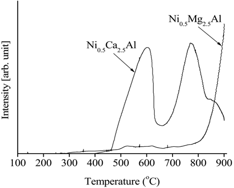
The H2-temperature-programmed reduction (H2-TPR) data obtained from the calcined Ni0.5Mg2.5Al and Ni0.5Ca2.5Al catalysts are shown in Figure 17. The reducibility of the Ni-based catalysts during the reduction process was an important factor in determining the level of reactivity since metallic Ni produced by the reduction process was in the active phase to initiate the reaction (e.g. CH4 dissociation). The reducibility of the catalyst was affected by, and can be estimated by measuring, the strength of the interaction between the active phase and the support. The Ni0.5Mg2.5Al catalyst exhibited a small peak at low temperatures (-600 ℃) and slightly increased at high temperatures (<700 ℃) while the Ni0.5Ca2.5Al catalyst exhibited two reduction peaks at lower temperatures, 580 and 770 ℃. Those two peaks can be assigned to complex NiOx species corresponding to Ni/support interactions[39]. Since the Ni0.5Mg2.5Al catalyst did not exhibit any H2 consumption until very high temperatures were reached (>750 ℃), it was determined that the Ni0.5Ca2.5Al catalyst exhibited relatively free NiO species. Previous investigations confirmed that the reduction process for the NiO-MgO would be initiated at very high temperatures (-900 ℃) since it produced a solid solution[26]. Additionally, the area under the TPR curve was clearly greater for Ni0.5Ca2.5Al than for Ni0.5Mg2.5Al and it can therefore be concluded that more Ni was reduced over the Ni0.5Ca2.5Al catalyst compared to the Ni0.5Mg2.5Al catalyst. This result also implied that the Ni0.5Mg2.5Al catalyst exhibited stronger interactions between the Ni and support since the reduction peaked at a higher temperature over the Ni0.5Mg2.5Al catalyst. These phenomena could be explained by comparing of the MgO, CaO, and NiO lattice sizes. Both MgO and CaO are face-centered cubic type oxides. However, only MgO has lattice parameters (a=4.2112 Å) and bond distances (A-B = 2.11 Å) close to those of NiO (a = 4.1946 Å, A-B = 2.10 Å), with the lattice parameters and bond distances of CaO being a=4.8105 Å and A-B=2.40 Å[27]. This result suggested that NiO can be more easily substituted into the MgO lattice[24,28]. A catalyst that is more susceptible to reduction can ultimately provide more active sites on the catalytic surface, leading to higher reactivity. Based on the TPR results, the Ni0.5Ca2.5Al was the more reducible catalyst and had higher initial reactivity in the partial oxidation, CO2 reforming and the oxidative CO2 reforming of CH4 processes relative to the Ni0.5Mg2.5Al catalyst, as shown in the reactivity data (Figure 3, Figure 4, and Figure 8). Additionally, since 720 ℃ was the reduction temperature used prior to the catalytic testing, the Ni0.5Mg2.5Al catalyst was only partially reduced.
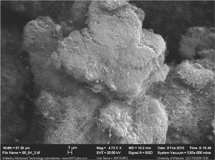
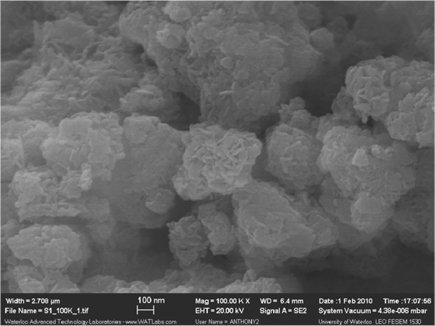
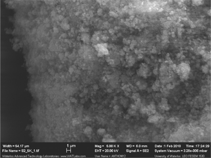
SEM images of the fresh Ni0.5Mg2.5Al catalyst are shown in Figure 18, which display a layered structure (also referred to as a “card house” shape[15]) at the surface of the catalyst. Alternatively, the Ni0.5Ca2.5Al catalyst did not exhibit a layered structure [27]. This result corresponds with the XRD results (Figure 13), where the data indicated that the Ni0.5Mg2.5Al catalyst possessed a layered structure. Additionally, this layered structure provided stronger interactions between the active site (Ni) and the support (Mg-Al), resulting is a lower reducibility, as confirmed above.
3.2.3. Carbon deposition analysis
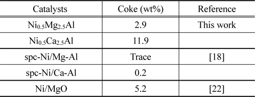
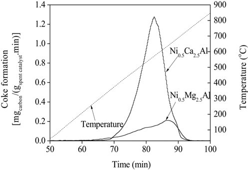
TPO experiments were performed to estimate the amount of carbon deposited on the catalytic surface after the reaction. The temperature of the catalyst bed was increased from 25 to 850 ℃ at a rate of 10 ℃/min. Mass spectrometry (MS) was used to detect the carbon oxides formed, which was then used to determine the amount of carbon present. The amount of carbon deposited on the catalysts can be estimated by calculating the area under the TPO curves plotted in Figure 19. The amounts of carbon deposited are listed in Table 2 and confirm that the Ni0.5Mg2.5Al catalyst exhibited a significantly stronger resistance to coke formation relative to the Ni0.5Ca2.5Al catalyst. The resistance to coke formation might be related to the stronger interaction between Mg and Ni ions, which subsequently inhibited coke formation. Alternatively, the Ni0.5Ca2.5Al catalyst, which was more easily reduced and resulted in Ni/Ca interactions being weaker, was more susceptible to deactivation via coke build-up.

Amount of carbon deposition on the Ni0.5Mg2.5Al and Ni0.5Ca2.5Al catalysts after 20 h, CO2 reforming at 700 ℃.
SEM images of spent Ni0.5Mg2.5Al (Figure 20) and spent Ni0.5Ca2.5Al (Figure 21) catalysts after 20 h of CO2 reforming of CH4 at 700 ℃ exhibited significant differences in the carbon deposition traits. Using the Ni0.5Mg2.5Al catalyst resulted in significantly less carbon fiber evidence relative to the Ni0.5Ca2.5Al catalyst.
Different approaches for the synthesis gas production using Ni-supported catalysts have been investigated. The typical methods to produce synthesis gas (partial oxidation and CO2 reforming of CH4) by HT-like catalyst were performed for short and long reaction periods in order to the investigate the effects of the structure of the catalyst on the stability and reactivity. Partial oxidation, CO2 reforming and the oxidative CO2 reforming of CH4 processes to produce synthesis gas were evaluated at 700 ℃ for 20 h in the presence of three different catalysts: Ni0.5Mg2.5Al, Ni0.5Ca2.5Al, and Ni/Al2O3. For the partial oxidation of CH4 during 20 h of reaction, the Ni0.5Mg2.5Al, Ni0.5Ca2.5Al, and Ni/Al2O3 catalysts exhibited similar levels of activity, which were close to the equilibrium levels, with the Ca- and Mg-containing samples exhibited no deactivation and the Ni/Al2O3 catalyst being deactivated. During CO2 reforming of CH4, the Ni/Al2O3 and Ni0.5Ca2.5Al catalyst conversions decreased as a result of coke formation, leading to deactivation of the catalyst. The Ni0.5Mg2.5Al catalyst exhibited high and stable reactivities for over 100 h. The Oxidative CO2 reforming of CH4, which combined the exothermic partial oxidation with the endothermic CO2 reforming of CH4, can facilitate heat transfer between the reactions. The addition of O2 reduced coke deposition on the catalysts since the oxygen can combust the surface carbon. Therefore, the catalytic activity levels for the partial oxidation and the oxidative CO2 reforming of CH4 processes could be maintained close to the equilibrium levels with less deactivation compared to the CO2 reforming of CH4. The Ni0.5Ca2.5Al catalyst exhibited the highest initial activity, but was deactivated quickly due to coke deposition. The Ni0.5Mg2.5Al catalyst exhibited the most stable reactivity over 20 h of reaction. Additionally, the Ni0.5Mg2.5Al catalyst exhibited excellent stability for the CO2 reforming of CH4, even in the absence of oxygen in the feed gas. TPR data indicate stronger interactions between the Ni and Mg compared to that with Ca, which seemingly correlates to catalyst stability in terms of decreased coke formation and subsequently allowing conversions and product yields to remain constant.