검색 전체 메뉴
PDF
맨 위로
OA 학술지
Single-Feed, Wideband, Circularly Polarized, Crossed Bowtie Dipole Antenna for Global Navigation Satellite Systems
  • 비영리 CC BY-NC
  • 비영리 CC BY-NC
ABSTRACT
Single-Feed, Wideband, Circularly Polarized, Crossed Bowtie Dipole Antenna for Global Navigation Satellite Systems
KEYWORD
Circular Polarization , Crossed Bowtie Dipole , Global Navigation Satellite System , Single Feed , Wideband.
  • I. INTRODUCTION

    Different services provided by satellite navigation systems have proliferated globally in the military arena as well as in the commercial and consumer markets. Four global navigation satellite systems (GNSSs) currently exist in the world-global positioning system (GPS), GLObal NAvigation Satellite System (GLONASS), Galileo, and Compass. Accordingly, antennas for GNSS applications have attracted considerable attention. An antenna for a GNSS receiver requires broadband characteristics fully covering the 1.146-1.616 GHz band, right-hand circularly polarized (RHCP) radiation with a wide beamwidth, and a high front-to-back ratio [1]. The current literature describes many broadband CP antennas for GNSS applications [2-7], where the CP radiation is realized in a broad frequency range by using several power combiners/splitters and phase shifters in the feeding network for these antennas. Unfortunately, this generally complicates the antenna design and fabrication.

    In 1961, Bolster demonstrated that single-feed crossed dipoles connected in parallel can be generated CP radiation [8]. The required power and phase relationships are obtained by the proper choice of the lengths of the two dipoles [8].

    This approach has been used to investigate single-feed composite cavity-backed crossed dipole antennas with a wide-beam CP radiation for GNSS applications [9-12]. Their operational bandwidths, however, do not fully cover the GNSS spectra. Recently, alternative engineering approaches have been taken for the single-feed crossed dipole antenna in order to broaden the operating bandwidth; a crossed dipole incorporated with parasitic loop resonators has achieved an impedance matching bandwidth of 1.9-2.9 GHz and an axial ratio (AR) bandwidth of 2.25-3.0 GHz [13]. A crossed dipole was designed with wide open ends for an impedance matching bandwidth of 1.99-3.22 GHz and an AR bandwidth of 2.30-2.90 GHz [14]. A modified magneto-electric dipole antenna with an overall size of 160×160×42 mm3 has enlarged the impedance matching bandwidth to 1.32-2.85 GHz and the 3-dB AR bandwidth to 1.69-2.75 GHz [15].

    This paper presents a single-feed CP crossed bowtie dipole antenna with a wideband characteristic; its matching impedance bandwidth for |S11| < -10 dB is 1.05-1.79 GHz and its 3-dB AR bandwidth is 1.12-1.64 GHz, both of which fully cover all GNSS frequency bands. Two bowtie dipoles are arranged orthogonally through double-printed rings, which contribute to generation of the CP radiation and enable direct matching of the antenna to a single 50-Ω coaxial line. A unidirectional radiation pattern is produced by equipping the proposed antenna with a planar metallic reflector. The antenna is first characterized by the ANSYS-Ansoft High Frequency Structure Simulator (HFSS) and then verified by measurements.

    II. ANTENNA GEOMETRY

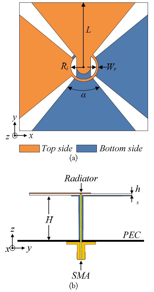
    Fig. 1 shows the geometry of the proposed antenna, which is composed of a radiator, a coaxial line, and a planar metallic reflector. The primary radiation element consists of two spatial orthogonal bowtie dipoles, which are designed on both sides of a 90×90 mm2 Rogers RO4003 substrate with a relative permittivity of 3.38, a loss tangent of 0.0027, and a thickness of 0.8128 mm. A pair of vacant-quarter printed rings is used as a feeding network and enables direct matching of the antenna to a single 50-Ω coaxial line and excitation of CP waves in the broadside direction. The outer wall of the coaxial cable is connected to the reflector and the bottom layer. A small hole is pierced into the bottom layer; the hole diameter is larger than that of the inner conductor to guarantee the separation between the bottom layer and the inner conductor. Finally, the inner conductor is connected to the top layer. The crossed bowtie dipoles are suspended at a distance H above a 120×120 mm2 square metallic reflector. The antenna was optimized to have an operational bandwidth covering all GNSS frequency bands. The design parameters of the optimized antenna are as follows: L = 44.4 mm, Ri = 7.4 mm, Wr = 1.4 mm, α = 81º, hs = 0.8128 mm, and H = 62.5 mm.

    III. RADIATION MECHANISM OF THE ANTENNA: A PROPER COMBINATION OF CROSSED DIPOLE AND ORTHOGONAL SLOT ANTENNA

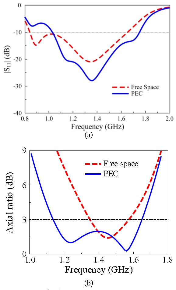
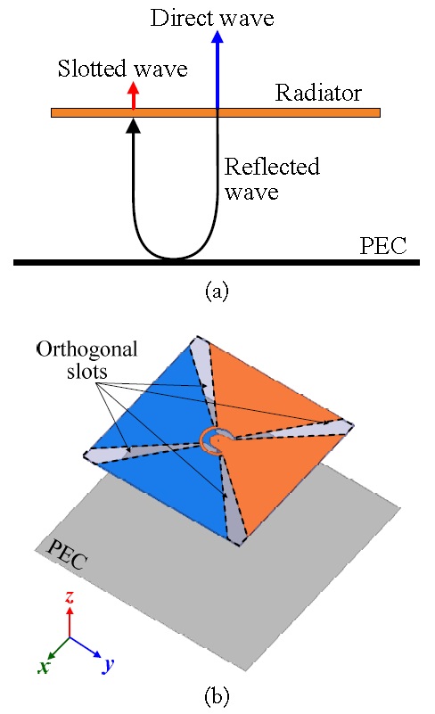
    For the initial purpose, the crossed bowtie dipole radiator was backed by a metallic reflector (perfect electric conductor [PEC]) to redirect one-half of the radiating wave to the opposite direction, and consequently, to improve the antenna gain and partially shield the object on the other side. More interestingly, the presence of the reflector significantly broadens the 3-dB AR bandwidth of the antenna. This is evident in Fig. 2, which shows a comparison of |S11| and AR values for the crossed bowtie dipole in different configurations.

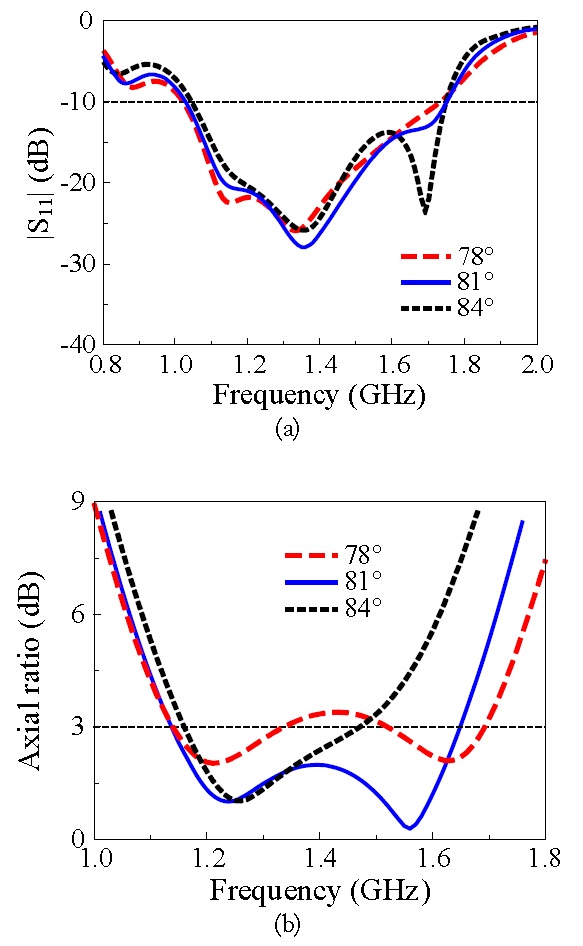
    This can be better understood by giving an explanation of the CP mechanism. The CP is achieved by using the approach reported in [8]; two dipoles with different lengths are chosen appropriately such that the real parts of their input admittances are equal and the phase angles of their input admittances differ by 90º. Accordingly, these conditions are obtained in the proposed antenna by using the vacant-quarter printed rings that made the dipoles slightly different lengths. Therefore, the antenna produces two resonances that perform a 90º phase differrence around desired frequency. The free space case clearly has two resonances at 0.9 and 1.35 GHz in the |S11| profile and one overlapping point of the two resonances with a 90º phase difference is evidence at 1.46 GHz (CP center frequency). For the PEC case, based on the CP explained above, four resonances are apparent in the |S11| profile and two CP center frequencies occur at 1.23 and 1.57 GHz.

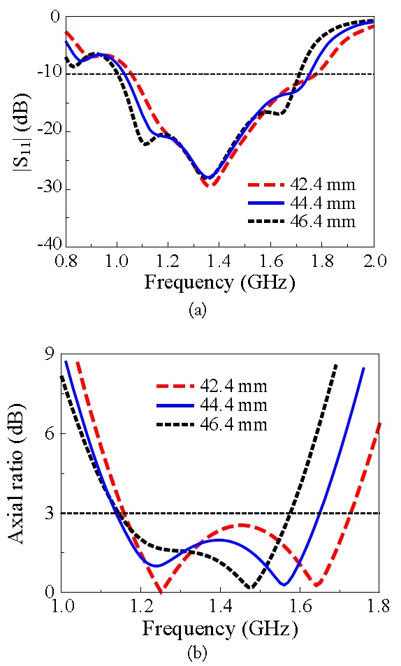
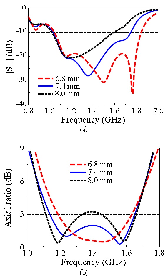
    Due to the presence of the planar metallic reflector, the radiated wave includes the direct wave from the radiator and the reflected wave from the ground plane, as shown in Fig. 3(a). The direct wave radiates from the radiator directly and the conditions for the CP radiation were obtained by double vacantquarter printed rings [9]. The reflected wave incorporated with the chosen slots between the adjacent bowtie arms (Fig. 3(b)) generates the additional resonances and the additional CP radiation for the antenna system. These phenomena can be favorably used to improve the antenna performance, as demonstrated in Fig. 2. The phasing feed for the CP radiation of the slot antenna was obtained by an appropriate combination of the slot shape and the printed rings. The proposed antenna is therefore a suitable combination of a crossed dipole and an orthogonal slot antenna. The antenna worked as a crossed dipole in the low frequency region, whereas it behaved as a slot antenna in the high frequency region. Accordingly, the lower CP center frequency (1.23 GHz) was generated by the crossed dipole, whereas the higher one (1.57 GHz) was generated by the slot antenna. This is confirmed by the effects of the slot shapes on the antenna performances, as shown in Figs. 4 and 5. Fig. 4 shows the simulated |S11| and AR values of the antenna for different angles of the bowtie dipole arm, α. With increasing α, which equivalently narrows the slot aperture, the impedance matching bandwidth and the lower CP center frequency showed little change, whereas the higher CP center frequency was considerably influenced. As shown in Fig. 5, as the bowtie length L increased from 42.4 to 46.4 mm in increments of 2 mm, the higher CP center frequency decreased significantly. The reason for this is likely due to an association between decreasing L associated and a smaller slot length; thus, the higher CP center frequency shifts upward.

    As previously noted, the CP radiation was decided by the printed rings at both operation modes, the crossed dipole and the cross slot aperture antenna. This is demonstrated in Fig. 6, which shows simulated |S11| and AR values for the proposed antenna for different radii (R) of the ring. Increases in R resulted in significant degradation of the impedance matching in the high frequency region (Fig. 6(a)), while the CP radiation improved in terms of minimum AR values, but the AR bandwidth narrowed (Fig. 6(b)). A value of R = 7.4 mm gave optimal results in terms of good impedance matching and good CP radiation.

    IV. MEASUREMENTS

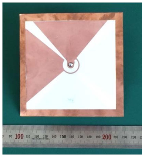
    The proposed antenna was fabricated and measured. The crossed bowtie dipoles were built on both sides of a Rogers RO-4003 substrate with a copper thickness of 17 μm using standard wet-etching technology. The reflector was a square 0.5-mm thick copper plate. An SMA connector was used at the input port to feed the radiator. An Agilent N5230A network analyzer and a 3.5-mm coaxial calibration standard GCS35M were used for the input impedance measurement of the prototype, as shown in Fig. 7. Another Agilent E8362B network analyzer and a full anechoic chamber with the dimensions 15.2 m (W)×7.9 m (L)×7.9 m (H) were used to measure the radiation patterns.

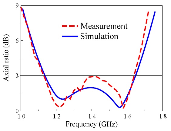
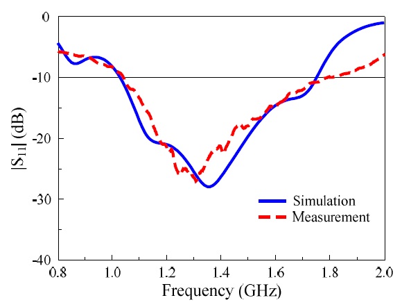
    Fig. 8 presents a comparison of the measured and simulated reflection coefficients for the proposed antenna. The measured impedance bandwidth for |S11| < -10 dB was 51.8% (1.05-1.79 GHz) whereas the simulated bandwidth was 52.1% (1.03-1.75 GHz). Fig. 9 shows the simulated and measured AR of the antenna. The measured 3-dB AR bandwidth was 37.7% (1.12-1.64 GHz) and had a discrepancy of 0.3% with the simulated 3-dB AR bandwidth of 37.4% (1.13-1.65 GHz). Both impedance and 3-dB AR bandwidths of the proposed antenna completely wrap the GNSS spectra (1.146-1.616 GHz)

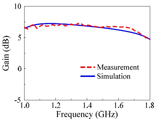
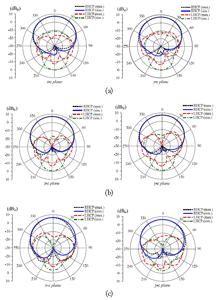
    The radiation patterns of the antenna at the center frequencies of the L5 (1.17 GHz), L2 (1.23 GHz), and L1 (1.57 GHz) bands in the two principle planes (Φ = 0° and Φ = 90°) are plotted in Fig. 10. The measurements agree well with the HFSS simulations and the proposed antenna shows RHCP. At 1.17 GHz, the measurements yielded a gain of 6.9 dBic, a front-to-back ratio of 12.6 dB, and half-power beamwidths (HPBWs) of 91° and 85° in the x-z and y-z planes, respectively. At 1.23 GHz, the measurements yielded a gain of 6.6 dBic, a front-to-back ratio of 12.5 dB, and HPBWs of 92° and 86° in the x-z and y-z planes, respectively. At 1.57 GHz, the measurements yielded a gain of 6.02 dBic, a front-to-back ratio of 12 dB, and HPBWs of 91° and 73° in the x-z and y-z planes, respectively. The antenna had a small gain variation within the 3-dB AR bandwidth. This is apparent in Fig. 11, which shows the broadside gain as a function of the frequency. The simulated gain ranged from 6.8 to 7.4 dBic within the 3-dB AR bandwidth, whereas the measured value ranged from 6.2 to 7.3 dBic. Additionally, the antenna showed a measured radiation efficiency of >93% in comparison to the simulated value of >98% within the operating bandwidth.

    V. CONCLUSION

    A single-feed CP antenna with wideband characteristics was presented. The antenna, with an overall 1.2-GHz frequency size of 0.48 λo×0.48 λo×0.25 λo, yielded a measured impedance bandwidth of 52.1% (1.05-1.179 GHz) for |S11| < -10 dB and a measured 3-dB AR bandwidth of 37.7% (1.12-1.64 GHz). The proposed antenna also yielded stable radiation patterns, RHCP, small gain variation, and high radiation efficiency across the operating bandwidth. These outstanding features make the proposed antenna a good candidate for GNSS applications, as well as for many other kinds of wideband wireless communications.

참고문헌
  • 1. Wang J. J. 2012 “Antennas for global navigation satellite system (GNSS)” [Proceedings of the IEEE] Vol.100 P.2349-2355 google cross ref
  • 2. Wang Z., Fang S., Fu S., Lu S. 2009 “Dual-band probe-fed stacked patch antenna for GNSS applications” [IEEE Antennas Wireless Propagation Letters] Vol.8 P.100-103 google cross ref
  • 3. Zhang Y. Q., Li X., Yang L., Gong S. X. 2013 “Dual-band circularly polarized annular-ring microstrip antenna for GNSS applications” [IEEE Antennas Wireless Propagation Letters] Vol.12 P.615-618 google cross ref
  • 4. Liu H., Fang S., Wang Z. 2013 “A novel multimode reduced-surface-wave antenna for GNSS applications” [IEEE Antennas Wireless Propagation Letters] Vol.12 P.1618-1621 google cross ref
  • 5. Li D., Guo P., Dai Q., Fu Y. 2012 “Broadband capacitively coupled stacked patch antenna for GNSS applications” [IEEE Antennas Wireless Propagation Letters] Vol.11 P.701-704 google cross ref
  • 6. Liu Q., Liu Y., Wu Y., Su M., Shen J. 2013 “Compact wideband circularly polarized patch antenna for GNSS applications” [IEEE Antennas Wireless Propagation Letters] Vol.12 P.1280-1283 google cross ref
  • 7. Lee W. S., Oh K. S., Yu J. W. 2012 “A wideband circularly polarized pinwheel-shaped planar monopole antenna for wireless applications” [Journal of Electromagnetic Engineering and Science] Vol.12 P.155-160 google cross ref
  • 8. Bolster M. F. 1961 “A new type of circular polarizer using crossed dipoles” [IRE Transactions on Microwave Theory and Techniques] Vol.9 P.385-388 google cross ref
  • 9. Ta S. X., Han J. J., Park I. 2013 “Compact circularly polarized composite cavity-backed crossed dipole for GPS applications” [Journal of Electromagnetic Engineering and Science] Vol.13 P.44-50 google cross ref
  • 10. Ta S. X., Park I., Ziolkowski R. W. 2012 “Dual-band wide-beam crossed asymmetric dipole antenna for GPS application” [Electronic Letters] Vol.48 P.1580-1581 google cross ref
  • 11. Ta S. X., Han J., Park I., Ziolkowski R. W. 2013 “Widebeam circularly polarized crossed scythe-shaped dipoles for global navigation satellite systems” [Journal of Electromagnetic Engineering and Science] Vol.13 P.224-232 google cross ref
  • 12. Ta S. X., Choo H., Park I., Ziolkowski R. W. 2013 “Multi-band, wide-beam, circularly polarized, crossed, asymmetrically barbed dipole antennas for GPS applications” [IEEE Transactions on Antennas Propagation] Vol.61 P.5771-5775 google cross ref
  • 13. Baik J. W., Lee T. H., Pyo S., Han S. M., Jeong J., Kim Y. S. 2011 “Broadband circularly crossed dipole with parasitic loop resonators and its array” [IEEE Transactions on Antennas Propagation] Vol.59 P.80-88 google cross ref
  • 14. He Y., He W., Wong H. 2014 “A wideband circularly polarized crossed-dipole antenna” [IEEE Antennas Wireless Propagation Letters] Vol.13 P.67-70 google cross ref
  • 15. Li M., Luk K. M. 2014 “A wideband circularly polarized antenna for microwave and millimeter-wave applications” [IEEE Transactions on Antennas Propagation] Vol.62 P.1872-1879 google cross ref
OAK XML 통계
이미지 / 테이블
  • [ Fig. 1. ]  Geometry of the proposed antenna: (a) top view of the radiator and (b) cross-sectional view with the metallic reflector.
    Geometry of the proposed antenna: (a) top view of the radiator and (b) cross-sectional view with the metallic reflector.
  • [ Fig. 2. ]  Simulated (a) |S11| and (b) axial ratio values of the antenna in different configurations. PEC = perfect electric conductor.
    Simulated (a) |S11| and (b) axial ratio values of the antenna in different configurations. PEC = perfect electric conductor.
  • [ Fig. 3. ]  Radiation mechanism of the proposed antenna: (a) radiated waves and (b) an orthogonal slot antenna.
    Radiation mechanism of the proposed antenna: (a) radiated waves and (b) an orthogonal slot antenna.
  • [ Fig. 4. ]  (a) |S11| and (b) axial ratio values of the proposed antenna for different α.
    (a) |S11| and (b) axial ratio values of the proposed antenna for different α.
  • [ Fig. 5. ]  (a) |S11| and (b) axial ratio values of the proposed antenna for different L.
    (a) |S11| and (b) axial ratio values of the proposed antenna for different L.
  • [ Fig. 6. ]  (a) |S11| and (b) axial ratio values of the proposed antenna for different radii of the ring, R.
    (a) |S11| and (b) axial ratio values of the proposed antenna for different radii of the ring, R.
  • [ Fig. 7. ]  The fabricated antenna.
    The fabricated antenna.
  • [ Fig. 8. ]  Comparison of simulated and measured |S11| values of the antenna.
    Comparison of simulated and measured |S11| values of the antenna.
  • [ Fig. 9. ]  Comparison of simulated and measured axial ratio values of the antenna.
    Comparison of simulated and measured axial ratio values of the antenna.
  • [ Fig. 10. ]  Radiation patterns of the antenna: (a) 1.17 GHz, (b) 1.23 GHz, and (c) 1.57 GHz.
    Radiation patterns of the antenna: (a) 1.17 GHz, (b) 1.23 GHz, and (c) 1.57 GHz.
  • [ Fig. 11. ]  Broadside gain as a function of the frequency.
    Broadside gain as a function of the frequency.
(우)06579 서울시 서초구 반포대로 201(반포동)
Tel. 02-537-6389 | Fax. 02-590-0571 | 문의 : oak2014@korea.kr
Copyright(c) National Library of Korea. All rights reserved.