Composite materials consisting of two or more constituents are intentionally combined to form heterogeneous structures having new electrical and mechanical characteristics. These materials can be categorized into several types of composites depending on the structures of the reinforced materials, e.g., fiber-reinforced and particle-reinforced composite materials. Some common fiber candidates are glass, carbon, graphite, ceramic, and aramid. In addition, suggested matrix types include polymer, metal, and ceramic/glass. The matrix plays an important role in fixing the reinforced material and determining the external pressure distribution [1]. Among these composite materials, carbon fiber reinforced polymer (CFRP) composites are widely used in shipbuilding, aerospace, and aeronautical devices, as they are lightweight and very strong. They also have a high modulus and are insusceptible to corrosion.
In particular, it is well-known that the reflector antenna for a satellite’s synthetic aperture radar (SAR), which requires high gain characteristics, may take up much space and be relatively heavy. An increase in payload weight and low-packaging efficiency relative to the waveguide or patch-typed antenna might cause an increase in the development costs. Hence, new composite materials are essential for a stable lightweight antenna that satisfies the electrical and mechanical performance needs in space environments. Many researchers have studied and investigated satellite antenna applications for newly designed advanced composite materials. For instance, the TDRSS communication satellite employs a graphite fiber-enforced rib in a parabolic dish antenna design with a diameter of 4.8 m. Another example is the 2002M graphite/epoxy applied to the reflector dish truss tube of a multi-purposed Application Technology Satellite launched by the National Aeronautics and Space Administration (NASA) in the United States. As these examples show, the development of composite material application technologies for large-scaled space antennas is now being accelerated with a focus on reducing weight [2]. As a composite material candidate, CFRP has also received a lot of attention [3-5]. However, to the best of our knowledge, there is a lacuna in the literature on CFRP electrical performance for satellite antennas, particularly regarding the importance of reliability and experience. In this article, we propose a measurement algorithm for the effective conductivity of an employed composite material called M55J/RS3 to confirm the applicability of the material for an SAR reflector antenna. In addition, we determine the radiation pattern of the reflector antenna using the proposed composite material as a reflector with commercially available software based on the ray tracing method. Section II summarizes the basic theory for the characteristic analysis of the employed CFRP specimen. In Section III, the measured and simulated reflection and transmission coefficients of the target specimen are listed by applying a 22.86 mm×10.16 mm standard rectangular waveguide WR90. Finally, Section IV shows the radiation behavior with simulated results using the obtained conductivity, and Section V offers our conclusions.
1. Calculating an Algorithm for Complex Permittivity
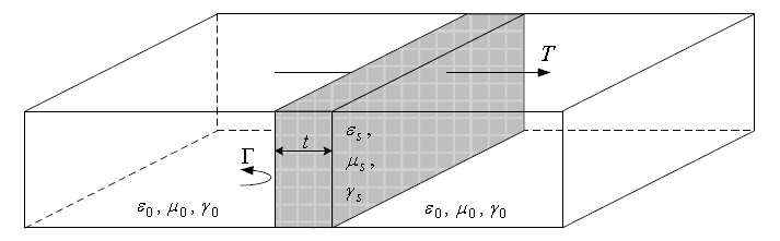
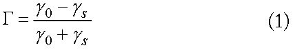
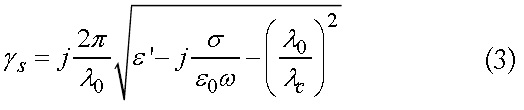
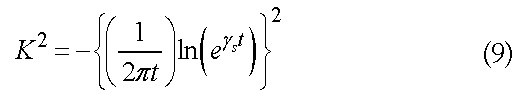
By employing a TEM-mode wave propagation between annular disks, it might be possible to obtain the effective complex permittivity and permeability using data related to reflection and transmission [6]. However, for easy fabrication and measurement, WR90 standard waveguides for X-bands are used to measure the electrical parameter values, as shown in Fig. 1. The equations describing the relationship between the reflection coefficient and propagation constant are as follows [7].
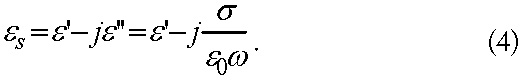
where
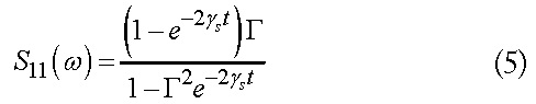
Hence, the total reflection and transmitted coefficients taking into account multiple reflection can be obtained as follows [6].
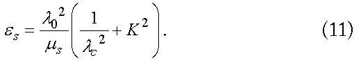
Through rigorous mathematical manipulations, the final complex permittivity and permeability can be described in detail, as follows.
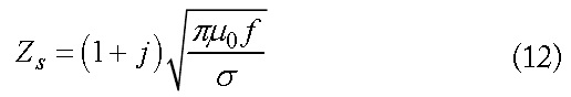
2. Calculating an Algorithm for Electrical Conductivity
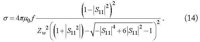
According to [6], complex permittivity is derived from reflectivity, transmission, and phase differences. However, a composite material having a high reflection coefficient leads to a significant fluctuation in the phase variation of the measured transmission coefficient because of the small |
where
III. MEASUREMENTS AND VERIFICATION
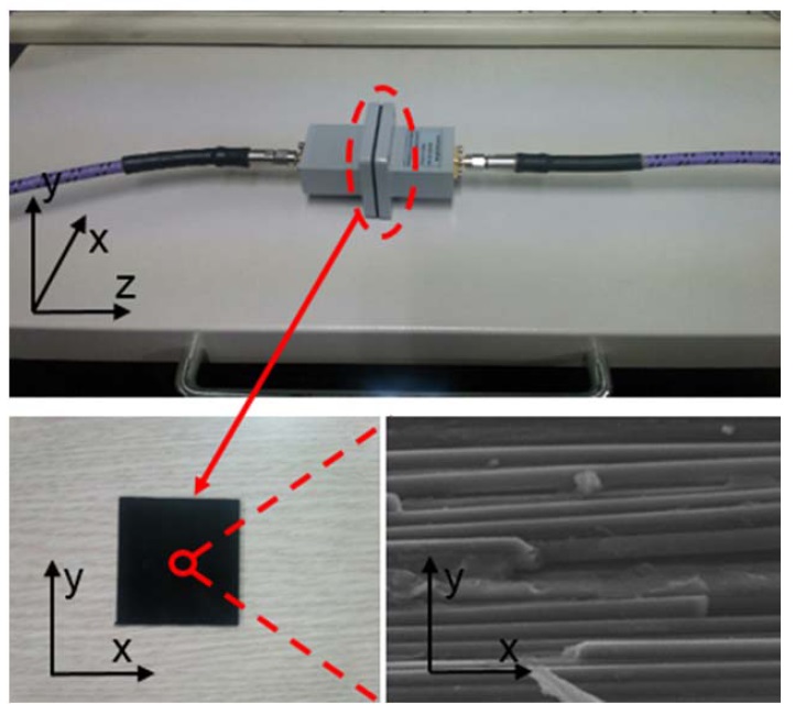
In general, the radiation efficiency of a reflector antenna with a central dish depends on the employed material of the dish. In order to achieve a high radiation efficiency, a composite material with a high conductivity should be adopted. The characteristics of composite materials like CFRP usually depend on the inside structure and the manufacturing process. For instance, the CFRP proposed in this paper is fabricated using an autoclave and oven. This hardens and laminates the employed M55J/RS3 prepreg material. The layered direction of the carbon fiber inside the CFRP is defined as a relatively unidirectional angle (0°, 45°, and 90°) to the direction of the electric field inside the transmission waveguide. Fig. 2 shows a measurement setup and a magnified view inside the proposed antenna M55J/RS3 prepreg material using a microscope.
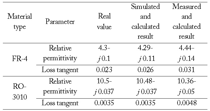
The operating frequency is 9.6 GHz, and the cutoff frequency of the used waveguide (22.86 mm×10.16 mm WR90) for material measurement is 6.56 GHz. Agilent N5230 PNA is employed to take measurements, and X-band through-reflectline (TRL) calibration is considered. Before the measurement of the fabricated antenna specimen, a test procedure for the validation of the given algorithm is examined with the dielectric specimen having well-known material data. As shown in Table 1, an employed dielectric specimen with complex permittivities of 4.3-

Applied results of the algorithm extracting the complex permittivity of well-known materials
For measurement convenience and fabrication ease, the sampled CFRP specimen has a dimension of 4×4 cm2, which is a little larger than the aperture of the waveguide used for the electrical measurement of the unknown CFRP material. In order to verify the complex permittivity calculating algorithm, a commercially available material having well-known data is employed, measured, and analyzed. As shown in Table 1, the employed substrates for the test have complex permittivities of 4.3-
The reason for the small discrepancy in the imaginary portion is thought to be the electromagnetic leaky wave and the surface roughness. This stems from the different sizes between the sampled specimen and the aperture, as well as from the tolerance in the etching process.
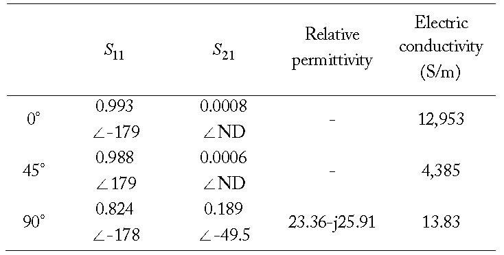
Table 2 summarizes four electrical characteristics-reflection, transmission, permittivity, and conductivity-that arise from the application of a new CFRP material to a future space reflector antennas. Three specimen types corresponding to laminating direction are reported with electrical performances. In general, the reflection and transmission characteristics will be changed according to the laminating directions of the employed materials, as listed in Table 2 showing the variations of conductivities.
[Table 2.] The electrical performances of a test CFRP specimen and the evaluated conductivity

The electrical performances of a test CFRP specimen and the evaluated conductivity
In the cases of the 0° and 45° laminating directions, the characteristics of reflection and transmission approach nearly 1 and 0, respectively, with remarkable variations in the phase of the transmission coefficient.
From the reflection coefficients, it can be conjectured that the employed spaceborne antenna material proposed in this work could be considered as a conductor whose conductivity can be obtained from Section II-2.
On the contrary, the case for the 90° laminating direction results in a permittivity of 23.36-
IV. APPLICATION OF NEW CFRP TO THE SAR REFLECTOR ANTENNA
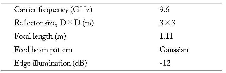
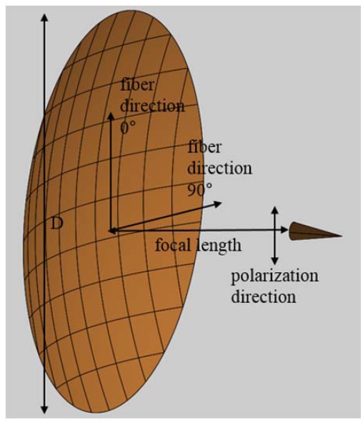
In order to verify the feasibility of the newly proposed M55J /RS3 material for future space applications on a SAR reflector antenna, the radiation characteristics of the reflector antenna are investigated by using previously obtained effective electrical conductivity. Table 3 and Fig. 3 describe several parameters and values for the performance investigation of the SAR parabolic reflector antenna [9].
[Table 3.] Parameters and values for the SAR performance analysis

Parameters and values for the SAR performance analysis
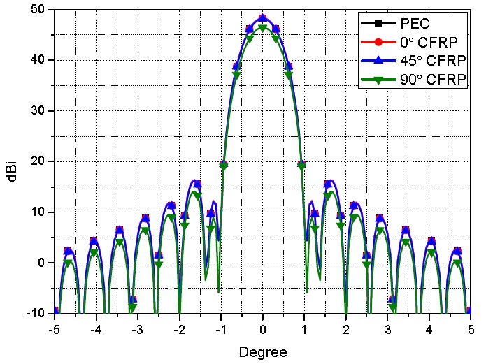
The simulation results in Fig. 4 show the radiation patterns with a sidelobe level using the commercially available PO-based software GRASP of TICRA (Copenhagen, Denmark).
It can be predicted from Fig. 4 that the gain differences in the boresight are 0.079, 0.137, and 1.886 dB according to the laminating directions 0°, 45°, and 90°, respectively.
This paper evaluated the feasibility of a newly developed space antenna material, M55J/RS3, for a SAR reflector antenna that must be light and highly conductive. From the electrical test results of the CFRP, it was found that electrical performances, such as reflectivity and transmission, depended on the curing method and laminating direction of the employed M55J/RS3 material. From the numerous fabrications and measurements, it was also found that the conductivity characteristics of the 0° and 45° laminating directions appeared to be better and higher than those of the 90° laminating direction. In addition, the feasibility of the newly proposed material for future space antennas was confirmed from the results in which the gain variations according to the material and ideal perfect electric conductor were too small to be ignored in the cases of the 0° and 45° laminating directions. Finally, it appears that the CFRP laminated in parallel to a single polarized direction can be applied to a future space reflector antennas requiring reduced weight and low loss characteristics.