Radio signals emitted from celestial sources enter detectors through feedhorns and polarizers after radio telescopes. In case of dual-linear polarization observations, an orthomode transducer (OMT) is used for polarization discrimination to transform the combined signal in the same frequency band from feedhorn into horizontal and vertical polarization signals. Since only a single mode or polarization state wave can be transmitted inside waveguides of heterodyne or incoherent detectors in millimeter-wave receivers, it is necessary that the input signal from feedhorn be separated into two orthogonal polarization components to propagate inside waveguide circuits in the receivers. The purpose of using an OMT in the radio-astronomical receiver systems is two-fold: First, when completely unpolarized source is observed, using an OMT and dual-polarization detection can increase the observation efficiency by a factor of two compared to a single polarization observation because only 50% of signal can be received without OMT in the receiver system. Second, an OMT enables to separate the input signal into two orthogonally polarized waves and measure polarization states of the radio source. Such a receiver for polarization measurement is called a polarimeter and the OMT for that receiver must have a very low cross-polarization performance. For a circular polarization observation, one can generally use a septum polarizer or a combination of an OMT and a 90-deg differential phase shifter to discriminate circularly polarized signals. A septum polarizer, which has a relatively simple structure, is widely used in satellite communication systems or radio astronomy receiver systems but the septum polarizer generally provides relatively narrow bandwidth performance. A combination of an OMT and a 90-deg differential phase shifter is preferred when broadband operation is needed because the OMTs and the differential phase shifters can have wider bandwidth operation than the septum polarizers (Srikanth 1997, Chung et al. 2010). In general, a waveguide-based polarizer is located between a feedhorn and a detector and the polarizer is a critical component which affects the operation bandwidth and the sensitivity of the receiver system. So, the development of a wideband OMT is important for duallinear and -circular polarization observations in the receiver systems.
In KVN 4-channel receiver system, septum polarizers are employed in 22 GHz, 43 GHz, and 129 GHz band receivers and a combination of an OMT and a 90-deg differential phase shifter was adopted by KVN 86 GHz band receiver for dual-circular polarization observation. As mentioned above septum polarizers have narrow bandwidth performance, wideband polarizers are required to be developed because most RF components in KVN receiver systems have wideband characteristics except a few devices including dual-circular polarizers. Thus, development of wideband polarizers is crucial to broadening the polarization observation bandwidth. As one of those efforts, a prototype D-band OMT has been designed and fabricated for the dual-circular polarization observation of KVN receiver system but measurements revealed that the prototype D-band OMT has higher cross-polarization than expected. The prototype D-band OMT was designed using E-plane split-block technique. Two halves blocks of the OMT were machined separately and assembled with assistance of guide pins. E-plane split-block structure is less sensitive to misalignment of the two halves blocks in assembling process. But the D-band OMT employs a square waveguide for the common input port and the misalignment in the square waveguide induces the cross-polarization. As the dimensions of the split-blocks are proportional to the wavelength of the signal, the cross-polarization caused by the misalignment becomes more critical in higher frequencies. To investigate the high cross-polarization measured in the prototype D-band OMT, a W-band OMT was fabricated by scaling the prototype D-band OMT and its performance was measured to verify the design of the prototype D-band OMT. Since the Maxwell equations are scale-invariant, the W-band OMT must have the same frequency response as the already developed D-band OMT. Since the W-band OMT was scaled from the D-band OMT, both of the OMTs have the same configuration except the dimensions. A waveguide-based OMT can be designed using one of several structures which include finline (Chattopadhyay et al. 1998), double-ridge (Dunning 2002), symmetric reverse-coupling waveguide (Navarrini & Nesti 2009), septum (Bøifot et al. 1990), T-waveguide junction (Dunning et al. 2009), turnstile structure (Pisano et al. 2007). The septum or vane was adopted as a polarization separating structure in this paper because its symmetric structure allows to have broadband operation intrinsically. OMTs using septum structure have been developed by several authors because of its wideband characteristics (Bøifot et al. 1990, Wollack et al. 2002, Narayanan & Erickson 2002, 2003). Even though the OMT developed in this paper has a similar structure as previously reported OMT designs, it was tried to make the OMT fabrication simple and low cost by optimizing the septum shape and the OMT structure for the application of KVN polarization observations. In this paper the design and the simulation result of the W-band OMT are presented and details of the fabrication and the measurements are also described.
2. DESIGN OF THE ORTHOMODE TRANSDUCER
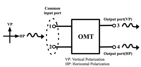
An electrical schematic of an OMT is shown in Fig. 1. Vertically and horizontally polarized signals are injected into the OMT through the common input port and the two orthogonally polarized signals are separated into two distinct output ports. The OMT is physically a 3-port passive device but electrically a 4-port device because of two different signals entering the common input port of the OMT. In general, the performance criteria or specifications of the OMT for the radio astronomy are return loss, insertion loss, isolation, and cross-polarization. As the specifications of the OMTs for the radio astronomy receiver systems depend on the polarization observation scheme, some typical specifications of the OMT for radio astronomical observations are as follows: required bandwidth ≳30%, return loss ≲ -20 dB, insertion loss ≲ -0.5 dB, isolation ≲ -30 dB, cross-polarization ≲ -30 dB. If the return loss of an OMT is not negligibly small, there may occur some standing waves between the feedhorn and the subreflector. Since such standing waves cause baseline ripples in the spectrum line observation, it would be better to have a return loss as small as possible. It is important to minimize the instrumental cross-polarization in the receiver system because polarized signals from celestial sources are extremely weak. In addition, the cross-polarization of the OMT should be smaller than other instrumental cross-polarizations due to radio-telescope, quasi-optical system, and feedhorn. Since the waveguide-based OMT is generally used in the cryogenically cooled receiver system, the insertion loss due to the ohmic loss is believed to be considerably reduced at cryogenic temperatures.
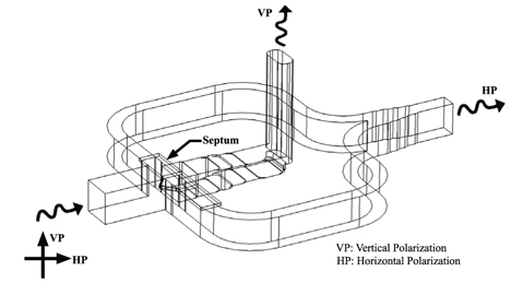
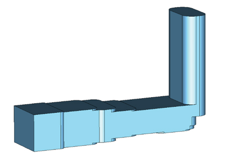
Fig. 2 shows an internal view of the W-band OMT developed in this paper. The OMT consists of several parts: square waveguide-based common input port, polarization separating junction including a septum or vane, square-to-rectangular transformer and mitre 90-degree E-plane bend for the vertically polarized wave, two side-arms and E-plane power combiner for the horizontally polarized wave. After each part of the OMT was designed by using CST MWS, which is a 3-dimensional electromagnetic simulation software, the whole OMT structure was simulated and the overall performance of the OMT was optimized by modifying dimensions of each part. The OMT employing a septum or vane for polarization separation can be considered as modification of a turnstile structure with two- fold symmetry which allows to have broadband operation (Bøifot et al. 1990).
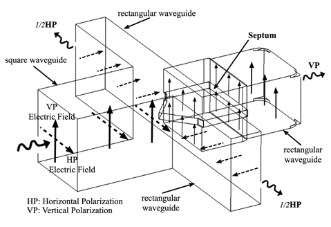
The square waveguide is used as the common input port of the OMT and its dimensions are 2.54 mm × 2.54 mm. The side length is the same as the WR10 waveguide’s broadside. Two orthogonally polarized signals enter the input square waveguide and are separated into different output ports through a junction including septum. Fig. 3 represents how dual-linear polarizations are separated into the vertically and horizontally polarized signals respectively by a septum inside the OMT junction. For vertically polarized wave (TE10 mode) which is perpendicular to the septum, the wave is divided into two parallel components passing to the impedance transformer and 90-deg mitre bend. In case of horizontally polarized wave (TE01) mode parallel to the septum, the wave is split into two components with 180- deg out of phase which propagate in the two side-arms respectively and are merged into one signal through the E-plane power combiner.
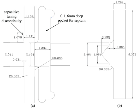
The junction is a square waveguide section where the main-arm and two side-arms meet. Since there are higher-order modes in the polarization separating junction, the dispersive reflection or reactance caused by higher-order modes must be tuned out for a good impedance matching. A capacitive tuning discontinuity is introduced on the waveguide broadside walls of the side-arms near the polarization separating junction, which is similar to the approach by Narayanan & Erickson (2002) but designed to make machining easier. OMT designs previous to Narayanan & Erickson (2002) employed discrete compensation pins to tune out the reactance (Bøifot et al. 1990, Wollack et al. 2002). But using the capacitive tuning step instead of such pins enables to scale the OMT to higher frequency bands thanks to direct machining and simpler assembling process of the OMT (Narayanan & Erickson 2003). Fig. 4 shows the geometry and dimensions of the OMT junction and septum designed in this paper. The septum geometry and dimensions are optimized by using CST MWS while simulating the performance of the OMT. In order to make fabrication of septum easier, the septum was designed to be as thick as possible while maintaining a good impedance matching for the both polarization signals. The thickness of the septum is also important in two aspects: OMT assembling process and scalability of the OMT in higher frequency application. The designed septum’s thickness is 0.232 mm for the W-band OMT. According to the simulation and measurement of the developed OMT, a small amount of increase in the septum thickness did not change the OMT performance. To have a good electric contact between the septum and the OMT blocks, the fabricated septum has a thickness of 0.251 mm.
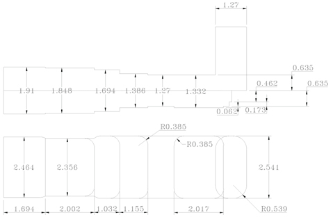
Figs. 5 and 6 represent the internal view and dimensions of the designed impedance transformer and 90-deg mitre bend of the OMT. The vertically polarized signal, which travels through the input square waveguide, is divided into two parallel TE10 modes via the septum. The two separated TE10 modes by the septum are combined in the square-to-rectangular waveguide or impedance transformer following the junction. The square-to-rectangular waveguide transformer has four sections and the dimensions of each waveguide section are optimized to have a good impedance matching of TE10 mode or vertically polarized signal. For easy machining with an end-mill, the waveguide steps of the transformer have rounded corners which are considered in the simulation of the OMT performance. The standard WR10 waveguide in the end of the transformer is followed by E-plane 90-deg mitre bend which connects with an oval waveguide. The vertically polarized signal in the main-arm is output through the oval waveguide which is perpendicular to the OMT split-block plane. The oval waveguide was chosen instead of the WR10 rectangular waveguide because it could be directly machined using a standard end-mill. The radius of corners in the oval waveguide was optimized so that there may be negligible impedance mismatching between the oval waveguide and the standard WR10 waveguide port. The blend radius of the corners in the oval waveguide is 0.539 mm.
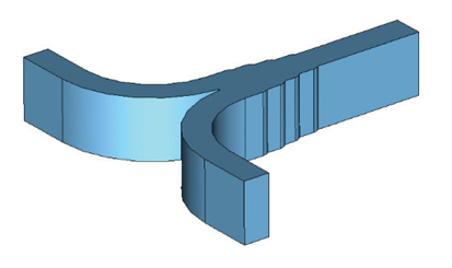
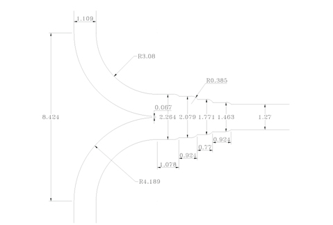
Figs. 7 and 8 depict the internal view and the dimensions of the E-plane power combiner or Y-junction designed in this paper. The horizontally polarized signal is transformed into two identical signals except 180-deg out of phase in the square waveguide junction via the septum. These two signals travel through the side-arms separately and are merged by an E-plane power combiner or Y-junction, which was based on a design by Kerr (2001). The output port of the horizontally polarized signal through the E-plane power combiner is the standard WR10 rectangular waveguide.
3. FABRICATION AND MEASUREMENT RESULTS
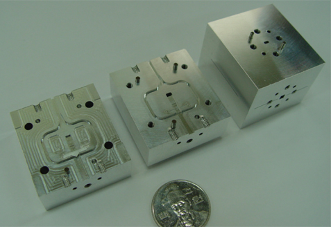
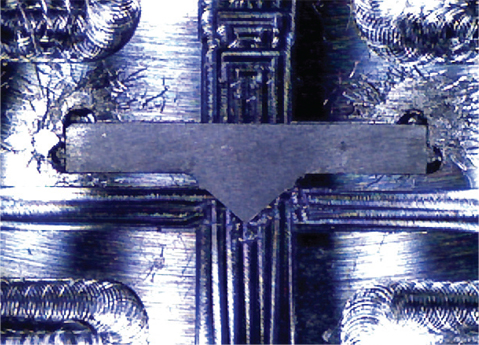
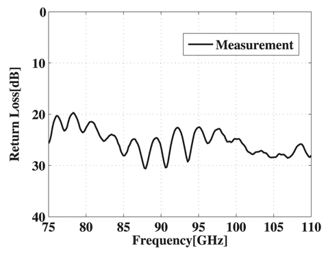
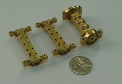
The OMT was built by using the E-plane split-block technique. The fabricated OMT consists of three mechanical parts: two split-blocks and a septum. Two split-blocks were fabricated in Aluminum alloy 6061 by CNC machining. In general, Brass with gold plating is used as material for fabrication of the waveguide-based devices at millimeter waves but it was known that Aluminum alloy can be used for low cost fabrication of waveguides and the insertion loss was measured to be sufficiently low even in D-band (Asayama & Kamikura 2009). The physical size of the fabricated OMT is 30.8 × 37 × 40 mm, which seems to be relatively bulky. The external dimensions were not optimized because the W-band OMT was directly scaled from the existing prototype D-band OMT. The fabricated OMT’s two halves split-blocks are shown in Fig. 9. Bosses with height of 0.308 mm around waveguide channels for the main-arm and side-arms and block recess for septum were machined to improve good surface contacts between the assembled split-blocks. Fig. 10 shows the septum being rested on the surface of one of the two halves split-blocks of the OMT. Aluminum and Brass were used to fabricate the septum by using direct CNC machining. Measurements showed that there is no great difference of the OMT performance between Aluminum alloy and Brass for the septum material. Aluminum alloy is preferred because of easier direct-machining compared to Brass. The septum fits well in block recess without deformation and upper and lower block halves mate precisely as designed. The assembled OMT has two output ports with the standard UG387 flange. The input square waveguide port also employs the standard UG387 flange but the guide pins are removed because of the rotation of the square-to-WR10 rectangular waveguide transition. To inject the horizontally polarized signal to the input square waveguide port, the square-to-WR10 rectangular waveguide transition is rotated by 90-degree on the common input port of the OMT. Since such a waveguide transition is not commercially available, the square-to-WR10 rectangular waveguide transition was fabricated for the OMT measurement using the E-plane split-block technique, which is represented in Fig. 11. For the measurements of the return losses and insertion losses of the OMT, well-matched square-to-WR10 transitions are needed between the OMT common input port and the WR10 port of the waveguide heads of a vector network analyzer. The transitions have a gradual linear taper in E-plane to adapt to the square waveguide (2.54 mm × 2.54 mm) of the OMT. S-parameter measurement was made using a pair of back-to-back transitions and the return loss of the square-to-WR10 waveguide transition is better than -30 dB for the design frequency band, which is shown in Fig. 12. Measured S-parameters of the square-to-WR10 waveguide transition were used in the measurements of the OMT.
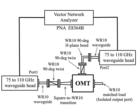
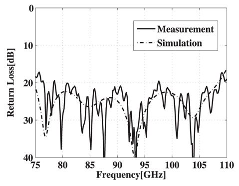
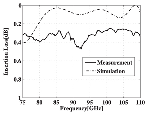
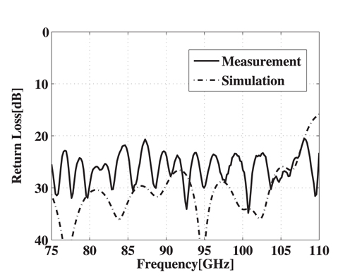
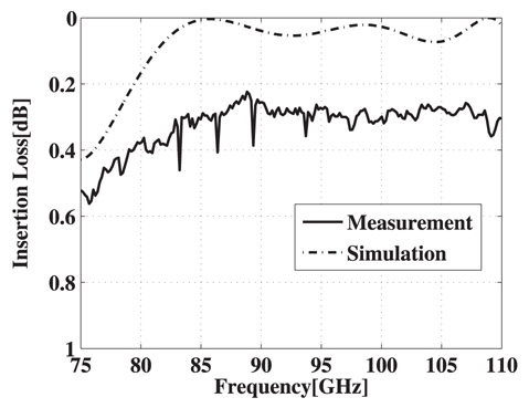
A block diagram of the measurement setup using a vector network analyzer is shown in Fig. 13. Measurement for the S-parameters of the OMT was performed using Agilent PNA E8364B with WR10 waveguide heads. For the S-parameter measurement of the OMT with the vertically polarized input signal, the square-to-WR10 waveguide transition is placed between the square waveguide port of the OMT and the port1 of the WR10 waveguide head. The output port of the OMT is attached to the port2 of the WR10 waveguide head so that the return and insertion losses of the OMT can be measured while the isolated output port of the OMT is connected to a matched waveguide load. In case of the horizontally polarized input signal, the square-to-WR10 waveguide transition is rotated by 90-deg using a 90-deg waveguide twist. Figs. 14 and 15 show measured and simulated return losses for the vertically and horizontally polarized input signals, respectively. The return losses for both polarizations are better than -20 dB across 80 ~ 108 GHz. Measured and simulated insertion losses for both polarizations are shown in Figs. 16 and 17. For the required frequency band, the insertion losses are better than -0.47 dB, which are greater than expected from the simulation. It is assumed that the surface roughness of waveguide channels in the OMT blocks leads to a major factor for greater insertion losses of the OMT under test. When the OMT is installed in a receiver dewar, the physical temperature of the OMT is cooled down to a cryogenic temperature (e.g. ~ 20 Kelvin). The receiver noise contribution due to the OMT insertion loss is believed not to be as great as at room temperature (~ 293 Kelvin).
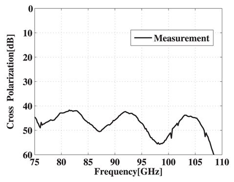
Considering the function of the OMT in a receiver system, which discriminates two orthogonally polarized signals, and extremely weak signals, the cross-polarization level is the most critical characteristic of the OMT, which is an unwanted polarization signal transmitted to an output port of the OMT. One can measure the cross-polarization by injecting a linearly polarized signal in the common input port and measuring a signal coupled to the isolated port of the OMT. Generally a square-to-WR10 transition may be used for the measurement of the cross-polarization but the cross-polarization of the transition itself must be very small not to affect the cross-polarization level of the OMT under test. Practically, it is difficult to measure the cross-polarization level of the square-to-WR10 waveguide transition. As described in the paper of Navarrini & Nesti (2009), the upper limit of the cross-polarization of the OMT can be estimated by short-circuiting the common input port of the OMT and measuring a coupled power between the two output ports of the OMT. This technique is a simple method for the cross-polarization measurement. Fig. 18 represents measured cross-polarization level of the OMT by using such a technique.
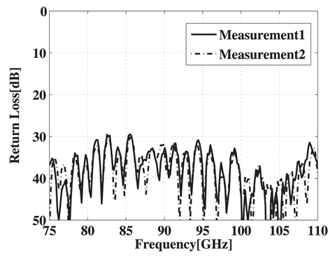
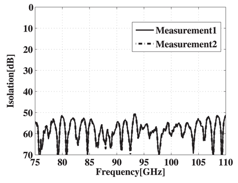
The isolation level is another critical characteristic of the OMT. One can estimate the isolation level of the OMT by measuring a coupled power between two output ports of the OMT under test while connecting a perfect matched load to the common input port of the OMT. But it is difficult to fabricate a well-matched square waveguide load at high frequency bands like W-band (75 - 110 GHz). An approximate method was used to estimate the isolation level of the OMT (Navarrini & Nesti 2009). The return loss of the square-to-WR10 waveguide transition open to the free space was measured to be better than -20 dB in Fig. 19. One can treat the common input port of the OMT open to the free space as a matched waveguide load. So, the isolation level of the OMT was estimated by measuring the coupled power between two output ports of the OMT while the common input port open to the free space. Measured isolation level of the OMT is shown in Fig. 20.
The design, simulation, fabrication, and measurement results of the W-band OMT for the polarization observation by KVN receiver system were presented in this paper. The OMT employing septum structure for polarization separation was realized using E-plane split-block technique. The OMT design enabled a low-cost fabrication and easy assembly. The purpose of the W-band OMT development is two-fold: First, the W-band OMT can be used in KVN 86 GHz band receiver because KVN 86 GHz band receiver has already employed a combination of an OMT and a 90-deg differential phase shifter for the dual-circular polarization. Second, the fabricated W-band OMT is a scale model of the prototype D-band OMT for higher frequency band of KVN system, which has been developed and measured to show higher cross-polarization than expected. The measured performance of the W-band OMT is generally in agreement with the simulation result. The return losses, insertion losses, cross-polarization, and isolation are better than -20 dB, -0.47 dB, -40 dB, and -50 dB, respectively across 80~108 GHz. The developed W-band OMT has a broad bandwidth of ~ 30%. According to the measurement result of the crosspolarization of the developed W-band OMT, it is believed that higher cross-polarization measured in the prototype D-band OMT is caused by split-block fabrication error or misalignment of assembly because the physical size of the W-band OMT is 1.54 times greater than the prototype D-band OMT and the misalignment error in the assembly of the W-band OMT might be less than the prototype D-band OMT. More precise fabrication tolerance and assembly technique are required to have lower cross-polarization level of the OMT at higher frequencies than W-band.