Space geodesy is now unthinkable without satellites, and specifically precise satellite orbit determination. The orbital motion of a satellite is a reflection of the total geophysical aspects of the Earth, including the non-symmetric geopotential and tidal effects, reference coordinate systems and transformation between them, and the irregular polar motions of the Earth. Precise orbit determination thus requires orbital dynamics and measurement models with maximum precision. Therefore, it is important to keep up to date with the latest geophysical models and reference systems in order to model the orbit dynamics as accurately as possible.
The main purpose of this article is to analyze the effects of the newest IERS Conventions on satellite orbit propagation through comparison with cases applying the previous conventions, i.e., IERS Conventions (2003). The choices of Earth-related models thus follow the IERS Conventions’ recommendations. The IERS has provided ‘Conventions (4 digits of year)’ (formerly ‘Standard’) for up to date Earth models in the form of technical notes since 1989, and this work dates back to the Project Monitor Earth Rotation and Intercompare the Technique (MERIT) (Petit & Luzum 2010). The latest IERS Conventions were released in 2010 and the previous conventions were provided in 2003. The IERS Conventions cover the geopotential models to atmospheric effects on radio propagation. This study focuses on the models related to orbit propagation, namely, the transformation between the celestial and terrestrial reference frame, the Earth’s geophysical models such as the geopotential and tidal models, and the Earth’s polar motion. First, for the celestial reference frame, the IERS adapted the definition given by the International Astronomical Union (IAU). At the IAU General Assembly in 2000, there were a series of announcements of new resolutions for the celestial reference system and the corresponding time system for the near Earth system, namely, the Geocentric Celestial Reference System (GCRS) and Geocentric Coordinate Time (TCG) (Kopeikin et al. 2011). The reference point was also newly defined as the so called Celestial Intermediate Origin (CIO) instead of the Equinox. Accordingly, the new models for the motion of the Earth pole were presented in addition to the traditional Equinox-based model. After these new concepts for the reference system was announced, a conference was held to discuss the implementation issues of the new IAU resolutions (Capitaine et al. 2002). However, the studies presented in the workshop were only dedicated to introducing the new concepts, but practical applications such as orbit propagation were not dealt with extensively. Vallado et al. (2006) conducted intense studies on implementation issues of these new IAU resolutions to orbit dynamics. However, they only dealt with coordinate transformation issues and, moreover, the new resolutions for the precession/nutation motions were announced after Vallado’s work.
This study analyzed how the new IAU2006 precession/nutation model adapted in the IERS Conventions (2010) affects orbit propagation. In addition, all the new geophysical models of the Earth in IERS Conventions (2010) are applied to orbit propagation and the results are compared with cases applying the previous guidelines in the IERS Conventions (2003). It should be noted that the some of the models in the IERS Conventions (2010) were developed before the release of the IERS Conventions (2010) and were already implemented to some orbit propagation software independently. The major contribution of this study is that it summarizes the effects of all Earth models given in IERS Conventions (2010) on orbit propagation.
The next chapter provides a brief description of the IERS Conventions (2010) compared with the 2003 Convention. Individual comparison results will then be presented for various orbit types using high precision orbit propagation software developed for this study. Lastly, a summary and contributions of this study are given in the conclusion.
The IERS Conventions are a collection of the Earth’s kinematic and physical models developed to date. The advances of the Earth’s geophysical model are not continuous, and thus the Conventions play an important role as guidelines when new software is being developed. However, application to existing software requires extensive investigation of the new models’ effects. Among the standards, the definitions of the celestial reference system and the relevant Earth pole motions are under the responsibility of the IAU, i.e., precession and nutation models. The geopotential and ocean tide models are also developed by various groups. In orbit propagation, there are two major areas to take into account: (i) the geopotential related models including the tidal motion, and (ii) the coordinate systems and the Earth rotation parameters related systems.
From the point of view of orbit propagation, the recommended models in the IERS Conventions (2010) are listed and also compared with the previous models in Table 1. The most important model in Table 1 is the geopotential model because its effect on satellite orbit is directive and the amount of perturbation is the largest (Montenbruck & Gill 2001). The ocean tide model is updated to the FES2004 model (Lyard et al. 2006). The update of the solar system ephemeris model from DE405 to DE421 (Folkner et al. 2009) affects modeling of third-body perturbation. The other models (?) are mostly related with the coordinate system transformation between the celestial and terrestrial reference frame. In particular, the precession and nutation model is updated based on the new IAU resolutions provided in 2006 and numerical models for small variations in polar motion due to libration, ocean pole tide, and free core nutation are suggested. Most of the items in Table 1 are applied to the orbit propagation software developed for this study, which will be described in the next chapter, and their effects on orbital motion are analyzed in the following chapter.
[Table 1.] Comparison between IERS Conventions (2010) and (2003).
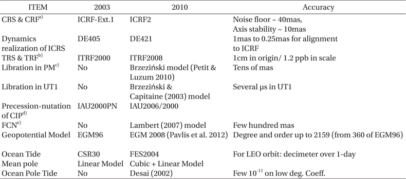
Comparison between IERS Conventions (2010) and (2003).
3. HIGH PRECISION ORBIT PROPAGATION BASED ON IERS CONVENTIONS
In this study, high precision orbit propagation software is developed in order to investigate the effect of the new IERS Conventions. The precision requirement in orbital dynamics is becoming more stringent because precision in space geodesy, except VLBI, is highly dependent on precise determination of satellite orbit. There are three pillars in precision orbit determination, i.e., actual measurements, numerical models for the measurements, and orbit dynamics. The advent of new satellite based measurement systems such as Satellite Laser Ranging (SLR) and Global Positioning System (GPS) has allowed high precision measurements. For this, however, the orbital dynamics should be as accurate as possible, corresponding to the new technology. The orbit propagator developed in this study plays an important role in satellite operation and also works as a basis of precision orbit determination.
The details of the applied model of the orbit propagator are summarized in Table 2. Vallado (2005) found that the orbit propagation are also dependent on the choice of interpolation scheme of the tabular data such as space weather and Earth rotation parameters. Here, the 8th order Lagrangian interpolation is used and we designed the target value to be located at the middle of the data set. Besides the environmental models, this propagator includes the perturbation models due to the non-symmetric geopotential, taking into account all the tidal effects of Table 1, atmospheric drag, solar radiation pressure, the third-body gravity of all the solar system planets and the Sun and Moon, and the General Relativistic effect. The body of a spacecraft can be modeled as a cannonball or a Box-Wing model, but a cannonball model is assumed in this study. Finally, the software is developed using C++ programming language except some open libraries such as IAU SOFA (Hohenkerk 2011).
[Table 2.] Models in orbit propagation software.
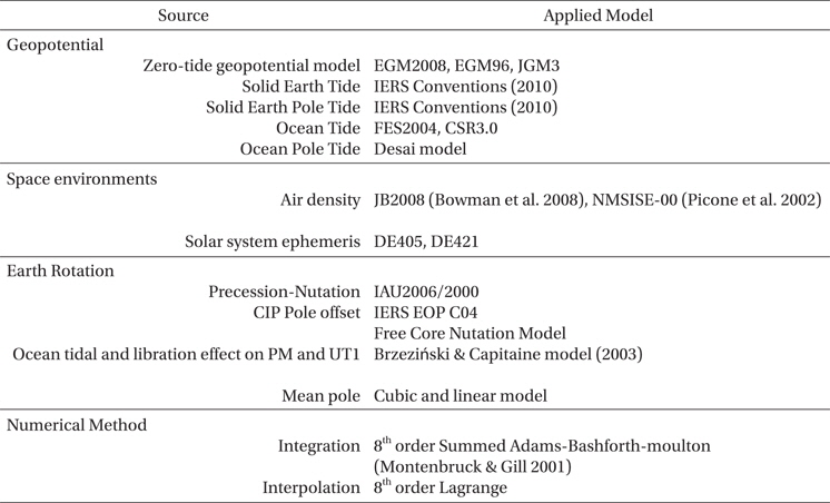
Models in orbit propagation software.
In this chapter, the effects of individual models presented in IERS Conventions (2010) are investigated through comparison with cases applying the previous Conventions (2003), namely, turning on/off the specific model. The reference orbit for comparison is defined as the case of applying all the models of IERS Conventions (2010) and all the perturbations in Table 2 simultaneously. The epoch is arbitrarily chosen as 2007-07-01 and the orbit is generated for one week. The Earth orientation parameters from the IERS EOP C04 are used, i.e., dUT1, pole offset, and the Celestial Intermediate Pole (CIP) offset. On the one hand, the IAU released a new transformation method between the celestial and terrestrial reference frame based on the CIO in addition to the Equinox-based method. Vallado et al. (2006) analyzed the advantages and disadvantages of both methods. In the current tests, both methods are implemented; however the Equinox based transformation is chosen for familiarity.
There are also some consideration pertaining to the reference frame and time system that should be noted. Although the IERS suggests GCRS and TCG as a reference time and frame for near Earth satellites, they are still not widely used because of their low familiarity (Kopeikin et al. 2011). The orbit propagator developed here also uses J2000 and Terrestrial Time (TT) as the reference frame and time for integration. The difference between GCRS and J2000 is time independent and the Euler angle difference is (-0.006819, 0.016617, 0.0146) arcsec, assuming 3-2-1 rotation. This difference corresponds to a maximum position difference of about 0.8 m for LEO (100 minute orbital period), 3.0 m for MEO (GPS), and 4.8 m for GEO. Other comparison results will be analyzed in the following sections.
4.1 Precession and Nutation Model ? IAU2006 vs. IAU2000
In this study, the tests are performed through comparison of two orbits, i.e., one from the IAU2006 precession/nutation model and the other from the IAU2000 model. The LEO orbits are chosen with a period of 100 minutes and various orbital inclinations, i.e., 10°, 30°, 60°, and 80°. Additionally, the GPS and geostationary orbit are also tested as representative examples of MEO and GEO. The update to the IAU2006 model is mainly for the precession model; namely, it replaced the previous IAU2000 model with IAU2006 based on the P03 precession theory of Capitaine et al. (2003). The resultant differences in rotation angles correspond to the differences in the transformed ECF position from J2000, specifically, about 1.5 mm for LEO, 4 mm for GPS, and 8 mm for GEO. In orbit propagation, the two precession/nutation models affect the calculation of geopotential acceleration. While integration of the equation of orbital motion is performed with respect to the celestial frame, for J2000, the geopotential model is based on the terrestrial frame. Namely, the two different precession/nutation models lead to a small deviation of ITRF position: in other words, a small angular shift of the geopotential model. This causes discrepancy of geopotential perturbation.
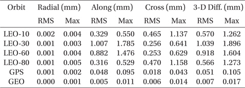
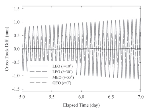
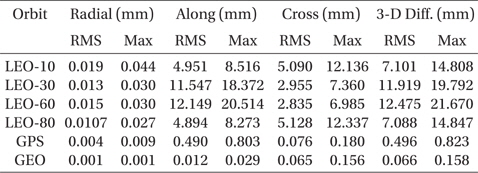
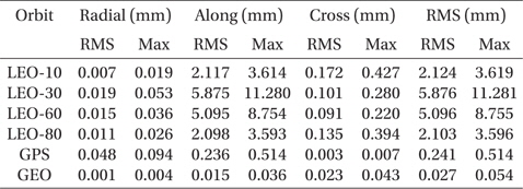
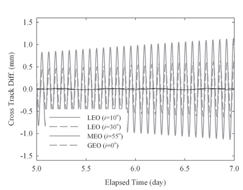
The comparison results of the two orbits from IAU2006 and IAU2000 are summarized in Table 3. The along and cross-track position differences are much larger than the radial-track one and the maximum difference is about 2 mm for the LEO case. Additionally, there is dependency on the orbital inclination. The cross-track different is larger in the low and high inclinations (10°, 80°) than the along-track. On the contrary, the medium inclination orbits show opposite results. The effect of the precession/nutation model decreases as the altitude of orbit becomes higher. However, this position differences are too small for detailed studies. The most important aspect of the effects is time-trend of orbit difference; namely, the along track position different varies secularly and the cross track difference shows a form of periodic variation. The main factor underlying these time-trends is that the model update leads to small variations of the geopotential model, and the right ascension of the ascending node and the argument of perigee are more sensitive to the geopotential variation than the other orbital elements (Schaub & Junkins 2003). These results show why the GRACE mission has twin satellites with the along-track discrepancy for research of geopotential variation (Han et al. 2006). It can be seen in the other tests described in this chapter that most of the geopotential model related changes show similar effects.
[Table 3.] Maximum and RMS difference of IAU2006 and IAU2000 precession/nutation model.

Maximum and RMS difference of IAU2006 and IAU2000 precession/nutation model.
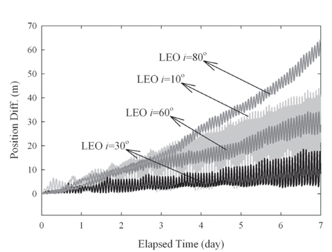
4.2 Geopotential model ? EGM2008 vs. EGM96
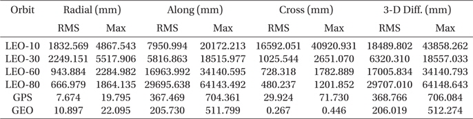
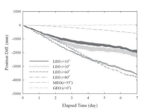
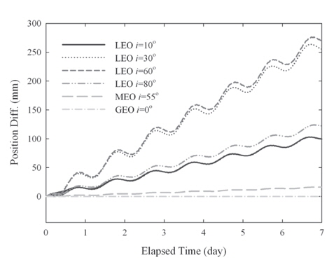
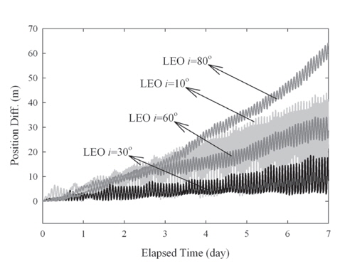
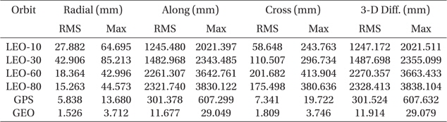
The update of the geopotential model to EGM2008 is arguably the most important change among the IERS Conventions (2010). The GRACE mission is the main contributor to the EGM2008 model that improves the accuracy and resolution of the geopotential model (Pavlis et al. 2012). The degree and order of the geopotential model increases up to 2190 by 2159 in EGM2008 from 360 by 360 in EGM96. The test results in terms of the RMS and maximum error for various orbits are summarized in Table 4 and the 3-D position differences for one week are plotted in Fig. 3. The secular drifts in Fig. 3 are due to the along-track component and the periodic variations are from the cross-track component. The radial track changes periodically with relatively small amplitude compared to the other components. Because the perturbation due to the gravitation field is conservative force, there should be no secular variable in the radial-track. The time-trend of the position difference is also similar to the results of the precession/nutation model case. The position difference reaches about 64 m for LEO and 0.5 m for GEO, and this is the largest difference among the cases tested in this research. The cross-track difference becomes higher as the inclination becomes lower. The trend of the cross-track can be understood using Lagrange’s planetary equations considering only the secular term and J2 gravitational perturbation (Schaub & Junkins 2003). Namely, the variation of the right ascension of the ascending node, which is connected to the cross-track difference, becomes larger as the inclination becomes lower. However, the along-track component is the most sensitive component to the geopotential deviation and is affected by various terms besides J2. The overall dependency on the orbital inclination shows that the equatorial and polar orbits are more sensitive to the geopotential variation than the medium inclination case. The medium inclination cases are less influenced by the change of the geopotential model.
[Table 4.] Maximum and RMS difference of EGM96 and EGM2008.

Maximum and RMS difference of EGM96 and EGM2008.
4.3 Ocean Tide model ? FES2004 vs. CSR 3.0
The ocean tides model directly affects the geopotential model coefficient as does the solid Earth tide. The specific contribution can be expressed as small changes of the geopotential (△
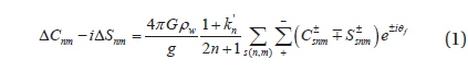
where G and g are the gravitational constant and acceleration. The other values,
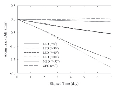
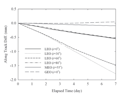
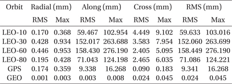
The comparison results are summarized in Table 5. Although the amplitudes of ocean tides are about one order of magnitude smaller than those of solid Earth tides (Montenbruck & Gill 2001), the amount of the position difference by the model changes is the second largest among the tests of the current study. In orbit propagation, a small fluctuation of the geopotential due to the ocean tide works mainly as a perturbation in the along-track direction. The maximum differences in the along-track direction are almost ten times larger than the cross component. As can be seen in Fig. 4, the effects of the update of the ocean tide model are noticeable mainly in the along-track direction.
[Table 5.] Maximum and RMS difference of FES2004 and CSR 3.0.
Maximum and RMS difference of FES2004 and CSR 3.0.
The centrifugal potential variation that is associated with the long term polar motions such as the Chandler wobble and annual variation causes deformation of the Earth (Desai 2002). These deformations are often called the pole tide. Among them, the ocean pole tide model is newly added in the IERS Conventions (2010). The model for the geopotential coefficient’s variation due to the ocean pole tide can be seen in the IERS Conventions (2010), and the detailed equations are thus not included here. Only the terms of the degree and order of (2,1) are considered in this test because they are dominant terms of the ocean pole tide, occupying about 90% of the total variation. The specific equation for the (2,1) terms is given as (Petit & Luzum 2010):

where (
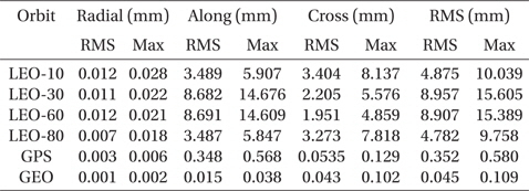
The test results of the ocean pole tide are summarized in Table 6. The effect of the ocean pole tide model is the third largest among the tests in the current study, following the geopotential and ocean tide models. The maximum difference is about 276 mm at
[Table 6.] Maximum and RMS differences caused by ocean pole tide.
Maximum and RMS differences caused by ocean pole tide.
4.5 Celestial pole offset from the IERS vs. FCN model
The celestial pole offset is a small correction to the CIP Coordinate (

where
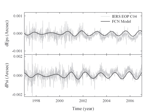
Here, first, the case of applying the CIP offset in orbit propagation is compared with the case without application of the CIP offset. Second, the former case is also compared with a case where the Lambert’s FCN model is applied (Lambert 2007). The two results are summarized in Tables 7 and 8, respectively. The case applying the FCN model shows smaller position differences compared to the case of not considering the CIP offset values. The amount of improvement is only about 30% in both RMS and the maximum position difference. Since the FCN model covers only the long-term periodic variation, not the daily fluctuation, this limited performance can be understood. Fig. 6 is the plots of the CIP offset from the model and EOP-C04 product of the IERS for 10 years. For the case of LEO with inclination of 30°, the maximum position difference is reduced from 19.792 mm to 15.605 mm with application of the FCN model. The time-trend of the position difference of this test is also similar to the previous tests that induce a small variation of the geopotential model. Namely, the along-track direction has a secularly varying pattern, while the cross-track has a periodic pattern. An example of the decomposed position differences is plotted in Fig. 7, i.e., the LEO with 60° in Table 8.
[Table 7.] Maximum and RMS difference with or without the CIP offset value.

Maximum and RMS difference with or without the CIP offset value.
[Table 8.] Maximum and RMS difference of the FCN model and the IERS product for the CIP offset.
Maximum and RMS difference of the FCN model and the IERS product for the CIP offset.
4.6 Ocean tidal and libration effects in polar motion
The IERS Conventions (2010) provide models to account for the motion of the CIP due to libration and ocean tides, which were not included in the previous conventions. Therefore, the pole coordinates (

where (
The comparison results of applying these values to orbit propagation are summarized in Table 9 for the same cases as considered in the previous sections. The amount of these variations is on the order of 10-4 arcsec, which is about one thousandth of (

Maximum and RMS differences caused by libration and ocean tidal motion of the polar motion.
The update of the solar system ephemeris from DE405 to DE421 in the IERS Conventions (2010) is the only one that is not related with the Earth. The ephemeris of the solar system is used to calculate the gravitational attraction due to the third bodies, which include all the solar system planets, the Sun, and the Moon. The Jet Propulsion Laboratory (JPL) continuously releases a solar system ephemeris data set named JPL DE with a numerical suffix. The DE405 is the most widely used ephemeris and is also recommended in the IERS Conventions (2003). The latest JPL ephemeris is the DE421, which is generated with fully consistent treatment of planetary and lunar laser ranging data (Folkner et al. 2009). The DE421 is known to have submeter accuracy for the lunar orbit, subkilometer for Venus, Earth, and Mars, several kilometers for Mercury, and tens of kilometers for Jupiter and Saturn. However, the time span covered by the DE421 is from 1900 to 2050 while the DE405 covers from 1600 to 2200.
The comparison tests for DE405 and DE421 are conducted for three orbital altitudes having typical inclination and the results are summarized in Table 10. In this test, a total of 10 bodies are considered, i.e., the Sun, the Moon, and 8 planets. Unlike the previous tests, the position differences caused by the update of the solar system ephemeris to DE421 become larger as the altitude increases, as expected. Namely, the attraction effect by the third body increases as they become closer. The decomposed position differences for three orbits are depicted in Fig. 9. The along- and cross-track differences are much larger than the radial-track component. While the along-track differences vary secularly, the cross-track components vary periodically, as in the other tests described above.
[Table 10.] Maximum and RMS difference of DE405 and DE421.
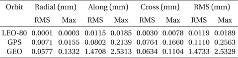
Maximum and RMS difference of DE405 and DE421.
This paper described the effects of the latest models of the IERS Conventions (2010) on orbit dynamics, i.e., a high precision orbit propagation model. The IERS provides a standard for the Earth system model under the name ‘Conventions’ and releases the products of the estimated Earth rotation parameters and the realization of the terrestrial reference system. The conventions presented by the IERS serve as a reference for the Earth satellite’s orbit propagation. Therefore, it is worthwhile to investigate the effects of the updated models in the latest IERS Conventions (2010) on orbit propagation through comparison with cases applying the previous conventions released in 2003.
In the current study, the influences of all seven models are analyzed using the propagated orbital positions for one week. Specifically, the tested cases are the updates of the geopotential model from EGM96 to EGM2008, the ocean tide model from CSR 3.0 to FES2004, the precession/nutation model from IAU2000 to IAU2006, and the ocean pole tide and the solar system ephemeris from DE405 to DE421. In addition to the model updates, the newly added models for the Free Core Nutation effects and the polar motion due to ocean tides and libration are tested here. For these tests, the high precision orbit propagator is developed using C++ programming language.
The effects of the geopotential model are the largest among the tests, reaching about tens of meters for LEO, and the next largest effects are caused by the ocean tide model update. The position differences are dominant in the along-track direction and their time-trends are secularly varying patterns. Unlike the along-track component, the cross-track difference varies periodically. The main reason for these time-trend patterns is that the effects of the model update lead to small variations of the geopotential model, and the right ascension of the ascending node and the argument of latitude are more sensitive to the geopotential variation than the other orbital elements. The effects of the update for the Earth’s pole motion such as the precession/nutation model are relatively small and the maximum position difference ranges from a few to tens of millimeters. The effects of the solar system model update become larger as the orbital altitude increases, while the changes of the Earth related model give opposite results, as expected. It would be worthwhile to extend the research conducted in this study to models not referenced in the IERS Conventions, for example, atmospheric density and solar activity models. The results of this study will play an important role to understand the relation between the Earth’s geophysical properties and orbital motion of satellites as well as satellitebased observations.