Recently, Chang'e-3 landed on the Moon on December 14, 2013. Through this event, China has joined the U.S. and Russia, as one of only three nations to make a controlled soft landing of an unmanned spacecraft on the Moon's surface. China announced that their lunar exploration will be continued with Chang'e-4 which is aimed to verify technologies for Chang'e-5. Chang'e-5 is scheduled to be launched in 2017 and it is expected to be China's first Earth returning mission. Indeed, the successful launch of Chang'e-3 revealed that the second race to the Moon has begun through Asian space powers which include China, Japan and India. To join the ranks of space industry powerhouses, Korea also plans to send up a lunar orbiter and lander before the end of the 2020, and planning to explore Mars, asteroids, and deep space. Therefore, Korean Astronautical Society has extended their interests to a lunar mission and numerous related basic studies have been widely performed. Korea Aerospace Research Institute is also performing pre-phase development and research for the lunar mission to be launched in next decades. For planned and on-going science activities to prepare the Korea’s future lunar missions, Kim et al. (2013) briefly summarized the current international cooperative researches for planetary sciences as well as nationwide new technology developments for Korean lunar projects.
Using impulsive thrust concept, Song et al. (2008) designed an optimal Earth-Moon transfer trajectory using direct departure from circular initial Earth parking orbit. Later, Song et al. (2009c) presented optimal Earth-Moon transfer trajectories using intermediate Earth departing loop orbits. An Earth-Moon transfer trajectory design considering spacecraft’s visibilities from the Daejeon ground station was also conducted by Woo et al. (2010). Recently, Choi et al. (2013) have analyzed various mission scenarios with four different combinations of Trans Lunar Injection (TLI) and Lunar Orbit Insertion (LOI) burn locations using Satellite Tool Kit. With low thrust concept, 2-dimensional optimal low thrust trajectory solutions were derived by Lee & Bang (2007), and Song et al. (2009a) presented optimal Earth-Moon transfer trajectories using both the constant and variable low thrust with 3-dimensional problem and with 3rd body perturbations. In additions, a lunar cargo mission design strategy using variable low thrust by combining both the analytical and numerical optimization method was presented by Song et al. (2009b). Using finite thrust concept, Song et al. (2010a) presented design results with TLI maneuver using finite thrust, and analysis on delta-V losses during lunar capture sequence using finite thrust with various on-board thrusters’ performances was performed by Song et al. (2011). An Earth-Moon transfer trajectory design by mixed impulsive and continuous thrust was also done by No & Jeon (2010). For a spacecraft located in close proximity to the Moon, optimal lunar landing trajectories with knowledge of parking orbits before the decent phase was conducted by Cho et al. (2009) with the assumptions of 2-dimensional problem. Later, Jeong et al. (2010) presented precise planetary landing method with terrain aided inertial navigation. In following research, Song et al. (2010b) developed precise lunar orbit propagator and analyzed the lunar polar orbiter’s lifetime.
Although numerous pre-design studies were performed as discussed above, most of the researches were only focused on trajectory design problem which are suitable for the phase of initial mission design. From the ground segment and operational point of views, more detailed analysis should be performed including; selection of appropriate tracking facilities depending on lunar mission phases, prediction of ground contact schedules and their associated tracking observables’ characteristics, etc. In the recent study done by Song et al. (2013) the ground contact opportunity for the fictitious low lunar orbiter with world-wide separated ground stations has been analyzed. In their work, both the cut-off angle of given typical stations and the orbiter’s Line of Sight (LOS) conditions were considered to determine the ground contact opportunities. In addition, they roughly analyzed the tracking observables’ characteristics (range, azimuth and elevation with their associated rates) while the spacecraft was orbiting around the Moon. However, in their work, they only treated for the spacecraft on the mapping phase around the Moon and it is certain that additional analysis should be performed for other lunar mission phases, i.e., a lunar transfer and capture, for completeness.
The main goal of this work is to additionally analyze the tracking schedule for the spacecraft on the phases of a lunar transfer and capture which were all omitted phases in the previous study done by Song et al. (2013). Moreover, through this work, expected measurements' characteristics during each phase with critical maneuvers (TLI, LOI and AAM: Apoapsis Adjustment Maneuver) are also predicted and analyzed. In Section 2, the ground tracking geometry for the spacecraft on the phases of a lunar transfer and capture is briefly discussed. Selected supporting tracking facilities’ locations are also treated in Section 2. Section 3 provides simulation results including tracking schedules for an Earth-Moon transfer and capture phase with predicted measurements’ characteristics during critical maneuver executions. Finally, in Section 4, conclusions are given. Although preliminary analysis results on navigation accuracy guidelines are provided through this work, it is expected to give more practical insights into preparing the Korea’s future lunar mission, especially with developing flight dynamics subsystem for ground segment.
2.1 Tracking condition geometry
There exist two necessary conditions to ensure the tracking of the spacecraft on the phase of a lunar transfer and capture. The first condition is that the spacecraft should lie above the horizon seen from a given tracking site, and this condition could be simply determined by finding slant-range vector from the site to the spacecraft. The second necessary condition is determined by the existence of the LOS between the spacecraft and the Earth. In Fig. 1, geometry of these two necessary conditions is briefly shown.
In Fig. 1, and indicate reference axes for E-EME2000 (Earth centered Earth Mean Equator of epoch J2000) coordinate system and and denotes unit vectors for topocentric-horizon frame meaning “South-East-Zenith” direction. Also, M-MME2000 refers Moon-centered Moon Mean Equator and IAU vector of epoch J2000 coordinate system. The first necessary condition can simply be determined using the angle
2.2 Selected transfer and capture scenarios
To analyze tracking measurements’ characteristics for future conceptual Korea’s lunar missions on the phase of Earth-Moon transfer and lunar capture, pre-designed trajectories’ states are directly adapted. For an Earth-Moon transfer trajectory, optimized result derived by Woo et al. (2010) is utilized. In their work, the optimal solutions of an Earth-Moon transfer is established with conditions of securing the spacecraft’s visibility at both TLI and LOI maneuver from the Daejeon station. They concluded that TLI burn initiated at 2017-02-15 11:00:31 (UTC) by the rate of about 3.153 km/s would place the spacecraft about 100 km altitude perilune through 90 deg inclined hyperbolic approach trajectory. The time of the closest approach is found to be about 2017-02-20 01:38:03 (UTC) as a result of about 4.61 days of transfer. After TLI maneuver, the spacecraft usually coasts along in the trans-lunar trajectory and performs LOI maneuver to be captured into the Moon. With a successful LOI maneuver, the spacecraft again per¬forms several de-orbit maneuvers, usually called AAMs, to change its orbit from the captured orbit to a desired mission operational orbit around the Moon. To design a hypothetical lunar capture sequence, two different intermediate elliptical capture orbits, having orbital periods of about 12 and 3.5 hours are assumed with the final mission operational orbit of 90 deg inclined having an altitude of 100 km with orbital period of about 118 minutes. This capture sequence is same as those of Lunar Prospector (LP) mission (Lozier et al. 1998) and other previous research (Song et al. 2008, 2009c, Woo et al. 2010). Song et al. (2008) showed that about 368.283 m/s for LOI, about 253.775 m/s for the 1st AAM, and finally about 242.257 m/s for the 2nd AAM delta-V are required to put the spacecraft into the final mission operational orbit. Corresponding maneuver burn times are 2017-02-20 13:38:03 (UTC), 2017-02-20 17:08:03 (UTC) and 2017-02-20 19:06:03 (UTC), respectively. In addition, note that these analyses are made under the assumptions that every maneuver is executed impulsively. More detailed information on the related trajectory design parameters could be obtained from Song et al. (2008, 2009c) and Woo et al. (2010).
2.3 Supporting ground facilities
To support tracking of the future conceptual Korea’s lunar missions, eleven tracking facilities are considered. It is assumed that Korea’s own tracking facility for a planetary mission is constructed at near the Daejeon province, and could be co-operated with three NASA’s Deep Space Network (DSN) sites; Goldstone, Canberra and Madrid (JPL 2013a), and seven NENs (Near Earth Networks); Norway Ground Station, Wallops Flight Facility, McMurdo Ground Station, Alaska Satellite Facility, Florida Ground Station, White Sands Complex Ground Station and Santiago Satellite Station (McCarthy & Carter 2010). Although Korea’s own tracking facility’s location is assumed to be near the Daejeon province in this work, readers may note that this may change in future days. In Table 1, considered tracking facilities’ geodetic locations and heights are shown.
[Table 1.] Considered tracking facilities’ geodetic locations and heights.

Considered tracking facilities’ geodetic locations and heights.
3.1.1 Tracking schedule analysis
Using optimized states of an Earth-Moon transfer trajectory, adapted from the former research as discussed, the tracking schedule for the spacecraft on a Earth-Moon transfer phase is analyzed first. Fig. 2 shows the analyzed result of tracking schedules, as a function of elevation angle variations (y-axis) from the given tracking sites. In Fig. 2, x-axis denotes elapsed time in days since TLI burn. For this simulation, elevation cut-off angles for each given sites are assumed to be 8 deg identical with the former researches (Song et al. 2009c, 2013, Woo et al. 2010).
As the pre-optimized solution has secured the visibility of the spacecraft at both TLI and LOI burn, the Daejeon station maintains contacts with the spacecraft at both TLI and LOI times as shown in Fig. 2. Also, for the moment of LOI burn, not only the elevation angle but also LOS conditions were satisfied seen from the Daejeon station. As for tracking schedules, it is discovered that the 1st contact will be made with the Daejeon station about 8.30 min of duration, and then the 2nd contact and 3rd contact will be made with Goldstone and Madrid DSN site with about 17.19 min and 24.56 min after TLI burn, respectively. Unlike other two DSNs (Goldstone and Madrid), the first contact with Canberra station is found to be made quite lately, about 341.77 min (5.69 hours) after TLI. This contact schedule means that only with the help of three DSNs, the 2nd contact will be made with Goldstone about 8.89 min after the contact lost with the Daejeon station. The existence of this contact gap, at early lunar transfer phase, is mainly due to the Korea's particular parking orbit's inclination (about 80 deg) used to design lunar mission, and this gap is found to be compensated only by the Alaska NEN among eleven tacking facilities that we have assumed. The start of contact with the Alaska site will be made at about 8.23 min after TLI burn, and this is about 0.07 min (4.2 sec) before the contact lost with the Daejeon station. For the reminder of about 4.61 days of a lunar transfer, three DSNs successfully covered the spacecraft during the entire journey to the Moon, and throughout this transfer, the Canberra station could play backup roles for the Daejeon station if we assume the Daejeon station to be the primary station. Like initial tracking strategy planned for the LP mission, the consequent contact gap could also be compensated by utilization of Tracking & Data Relay Satellite System (TDRSS). Actually, the LP mission was planned to use TDRSS to track the spacecraft during about 19 min of contact lost just after TLI burn. However, due to the limited TDRSS capability, LP mission failed to obtain a tracking data which affected the correction maneuver plan and other mission time schedules significantly, as the readiness of full state estimation within confident level of accuracy was entirely delayed (Beckman & Concha 1998). Lessons learned from the LP mission tells that obtaining stable tracking measurement after TLI burn is another crucial factor which should be considered at the early lunar transfer trajectory design phase, and utilizing NENs could be considered as one of the options to enhance tracking availability of the spacecraft. Although presented results showed that only Alaska NEN facility could compensate the tacking gap made when the spacecraft is only tracked only through DSNs, readers may note that this is only valid with given scenario. In addition, other eleven NENs may play significant role, strongly dependent to mission scenarios, to support DSNs while the spacecraft is at the early lunar transfer phase.
For detailed contact schedule analysis, the Daejeon station made 6 times of total contact during the 4.61 days of lunar transfer with 2,780.83 min (46.34 hours) of overall contact duration. The mean durations for each contact found to be about 463.47 min (7.72 hour). For other tracking facilities, 5 times of total contact is made with mean duration of 556.73 min (9.27 hour), 461.41 min (7.69 hour), 685.84 min (10.93 hour), 337.97 min (5.63 hour) for Goldstone, Madrid, Canberra and Alaska station, respectively. More detailed station’s tracking characteristics are provided in Table 2. In Table 2, the coverage ratio indicate the percentage rate that the typical station could cover the spacecraft out of entire Time of Flight (TOF) (4.61 days for this case) required for lunar transfer. As shown in Table 2, the Daejeon station could cover the spacecraft on the phase of lunar transfer with almost equal orders of coverage ratio compared to those of covered by other DSNs, and it seems that placing Korea’s tracking facility for a lunar mission near the Daejeon province is quite reasonable.
[Table 2.] Detailed contact analysis results for an Earth-Moon transfer phase.
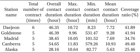
Detailed contact analysis results for an Earth-Moon transfer phase.
Although the future location of Korea’s tracking station might change to other province, our current interests are to analyze the tracking coverage rate for the spacecraft on a lunar transfer phase with the Daejeon station. Therefore, additional simulation was performed with different transfer scenarios. Derived tracking schedules with the Daejeon station is shown in Fig. 3 with range variation profiles. In Fig. 3, x-axis denotes elapsed time in days since TLI and y-axis indicates range variation profile during the transfer. Also, the tracking availability is distinguished with solid line (tacking available), and dotted line (tracking lost). At the top of the Fig. 3, result with transfer scenario which was already discussed through subsection of 2.2 is plotted, and it will be called as case A hereinafter. At the middle and bottom of the Fig. 3, new transfer scenarios are adapted from the work done by Choi et al. (2013). The scenario shown at the middle of Fig. 3, will be called case B hereinafter, the time of optimal TLI burn is found to be executed at 2020-01-24 21:03:13 (UTC) and lunar closest approach is made at 2020-01-29 21:03:13 with about 3.111 km/s of TLI burn. For the scenario showed at the bottom of Fig. 3, will be called case C hereinafter, the optimal TLI burn is found to be made at 2020-01-15 01:54:41 (UTC) with about 3.107 km/s of TLI to place a spacecraft at a perilune through arrival hyperbolic trajectory at 2020-01-20 01:54:41 (UTC). In both cases (B and C), TOF is assumed to be as 5.00 days and readers may refer Choi et al. (2013) for more in-depth trajectory information. In Table 3, assumed three different (case A, B and C) transfer scenarios’ characteristics are summarized.

Brief summary of three different (case A, B and C) transfer scenarios’ characteristics. More details of each scenario could be found through works done by Woo et al. (2010) for case A, and from Choi et al. (2013) for cases B and C.
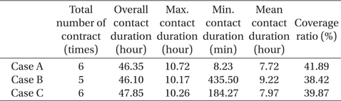
From Fig. 3, it can be easily noticed that the Daejeon station will provide 5 or 6 times of contact regardless of different lunar transfer scenarios. As expected, the major conditions which determines the overall total contact number is the initial location of TLI burn, however, despite of the initial location of TLI burn, overall total contact duration and coverage rate discovered for the Daejeon station remained near about 46 ~ 48 hours which is about 38 ~ 42 percent coverage. Indeed, about 40 hours of overall total contact duration, out of 5 days of lunar transfer, could be expected if we roughly estimate the total contact duration for any DSNs. Therefore, the result shown for the Daejeon station’s overall total contact duration and coverage rate is again reasonable for the location of the Korea’s future tracking facility. Although provided results are made under the assumptions that the Korea’s future tracking facility is located near the Daejeon province, simulation results may not seriously differ from those of results made with other candidate locations near at Korean peninsula. Table 4 compares the results of tracking characteristics derived with three different Earth-Moon transfer scenarios.

Comparisons of contact parameters with the Daejeon station for three different transfer scenarios. Case A is for the 2017 mission scenario adapted from Woo et al. (2010) and Case B and C are for the 2020 missions that described in Choi et al. (2013).
3.1.2 Tracking measurements prediction for TLI maneuver
Just after TLI burn, the biggest maneuver among the entire lunar mission, an accurate determination of a spacecraft’s states is one of the most important factors for the mission to be successful. Therefore, the tracking parameters’ characteristics during a lunar transfer phase are predicted and analyzed in this subsection which could give more practical insights into preparing the Korea’s future lunar mission. In Fig. 4, predicted tracking parameters’ characteristics derived with an Earth-Moon transfer scenario, case A, seen from the Daejeon station is shown. X-axis in Fig. 4 denotes elapsed time in days since TLI burn, and y-axis on the top of Fig. 4 denote range rate variation during the transfer. At the middle of Fig. 4, azimuth rate is shown and elevation rate is shown at the bottom of Fig. 4. Minus sign in x-axis indicate time before TLI burn where the spacecraft is located at the parking orbit. In additions, solid line represent that the spacecraft could be tracked from the Daejeon station and dotted line indicate that the spacecraft is not within a tracking condition. As expected, it can be easily noticed from the Fig. 4 that every tracking measurements has discontinuous points at zero elapsed time due to about 3.153 km/s of impulsive TLI burn. For range rate variation, about -7.15 km/s of range rate is predicted for prior TLI burn, and just after TLI burn, about -9.82 km/s of range rate is expected. For azimuth rate, about -0.05 deg/s and about -0.08 deg/s is expected, and for elevation rate, about 0.11deg/s and about 0.17 deg/s is expected for both just prior and after TLI burn, respectively. From these predicted rate variations due to TLI burn, following general conditions could be easily predicted; the spacecraft will more be accelerated just after the tracking signal is obtained from the Daejeon station, elevation will be increased dramatically, and the spacecraft will fly over to eastward seen from the Daejeon site. Actually, generated lunar transfer scenario (case A) is found to execute TLI burn just as soon as the spacecraft arises from the southern local horizontal plane (azimuth about 178.73 deg and elevation about 8.10 deg) seen from the Daejeon station, and these conditions lead the spacecraft not to be traceable during the coasting phase where the spacecraft is usually staying at a parking orbit to check its systemic readiness to start long journey to the Moon.
Such a large TLI burn, executed near the Earth, results an order of km/s level variations for a range rate and milideg/ s level for both angular tracking rates. Although TLI burn causes quite large amount of tracking parameters’ variations, as it is the biggest maneuver among the entire lunar mission and executed near at the Earth, the amplitude of every tracking parameters’ variations profile are dramatically decreased as the spacecraft approached to the Moon. From these phenomena, we could easily expect that more accurate mathematical models of flight dynamics and measurement, as well as a very precise location of tracking facilities are required for precise estimation of the spacecraft’s trajectory near around the Moon. Indeed, the accuracy of a thousandths of a degree for the DSN antenna pointing is not accurate enough to be used in determining the trajectory of a distanced spacecraft, and they are valid only for acquiring the spacecraft’s signal (JPL 2013b). To determine a distanced spacecraft’s trajectory with fair accuracy, angular and radial position could be determined with the help of Very Long Baseline Interferometry (VLBI), called ‘Differenced One-way Ranging (DOR)’, or by a method called Differenced Doppler (JPL 2013b). Details of these methods are not treated here as they are out of the scope of this work. However, the first order analysis for tracking parameters’ characteristics for the spacecraft on a phase of lunar capture is briefly performed with predicted measurements in the following subsection of 3.2.2.
3.2.1 Tracking schedule analysis
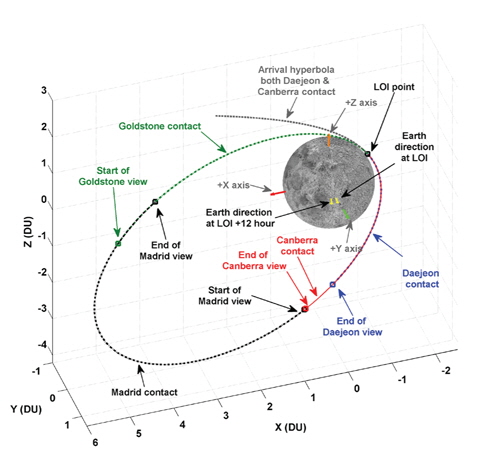
In this subsection, tracking schedule for the spacecraft on a phase of lunar capture is analyzed. The sequence of lunar capture phase is established as discussed in Subsection 2.2. In Fig. 5, geometry of lunar arrival hyperbolic trajectory and the 1st elliptical capture orbit including predicted tracking schedules is shown.
In Fig. 5, the spacecraft’s states are expressed based on M-MME2000 coordinate system and DU is used for every axes’ unit which is about 1738.2 km. Also, note that arrival hyperbolic trajectory is plotted from an hour before LOI burn. At the lunar arrival phase, optimized Earth-Moon transfer trajectory guided the spacecraft to be the ‘face-on’ orbit which means that LOS conditions between the spacecraft the Earth is always satisfied during lunar capturing phase. This LOS conditions’ geometries are apparently shown in Fig. 5 through the Earth direction vector at the times of both LOI and 12 hours later LOI burn with +Y axis of capture orbits. During the arrival hyperbolic trajectory, it is found that the spacecraft can be tracked with both the Canberra and the Daejeon station. The contact with the both station will last after LOI burn, and contact lost will be around at 69.95 min (1.17 hours) after LOI burn for the Daejeon station, and about 93.05 min (1.55 hours) after LOI burn for the Canberra station. Thus, the Canberra station will contact more with the spacecraft about 23.10 min then the Daejeon station for this simulation case. About 94.30 min (1.57 hours) later LOI burn, the Madrid station will continue to track the spacecraft and this is about 17.4 sec after contact lost with the Canberra station. However, note that this gap will be strongly dependent on the assumption of given sites’ elevation cut-off angles. Contact lost with the Madrid station will be around about 598.66 min (9.98 hours) after LOI burn, meaning that duration of the spacecraft contact with the Madrid station is about 504.36 min (8.41 hours) which is about 70.08 % of entire 1st capture orbit’s orbital period. About 53.59 min before the end of the Madrid station view, the Goldstone station can acquire tracking signals from the spacecraft and can track the remainder of the 1st capture elliptical orbit until the 1st AAM burn. Therefore, for the first lunar capturing sequence, the spacecraft can be tracked by the Daejeon and the Canberra station at the time of LOI burn, and at the time of the 1st AAM burn, only the Goldstone station can track the spacecraft.
For the 2nd lunar capture phase, the predicted tracking schedule is shown in Fig. 6. The 2nd lunar capture phase lead the spacecraft to be inserted into the 2nd capture elliptical orbit (with about 3.5 hours of orbital period) through the 1st AMM, and to the final mission operational orbit (circular orbit with 100 km altitude) through the 2nd AAM, respectively. As a result, it is found that the Goldstone station could maintain contact with the spacecraft through the times from the 1st AMM until the 2nd AAM. The Canberra station acquired tracking signal at about 101.42 min (1.69 hours) after the 1st AAM and continued to track the spacecraft including the 2nd AMM burn. Therefore, about 101.42 min (1.69 hours) after the 1st AAM burn, the spacecraft could be tracked from two stations, the Goldstone and the Canberra, which is certainly helpful to improve the orbit determination accuracy. After the 2nd AAM burn, after a successful insertion into the mission operational orbit, the two DSN stations (The Goldstone and the Canberra) are capable of tracking a spacecraft continuously. For the Daejeon station, the contact will be started about 98.38 min (1.64 hours) after the 2nd AAM burn with about 129.62 deg of azimuth and about 8.01 deg of elevation angles seen from the Daejeon station. Therefore, the spacecraft could be tracked by three different stations about 98.38 min (1.64 hours) after the 2nd AAM burn.
From the analyses made above, the spacecraft can be tracked by the Daejeon and the Canberra stations at the time of LOI burn and only by the Goldstone station at the time of the 1st AAM burn. For the 2nd AAM burn, the Goldstone and the Canberra stations will provide the tracking data for the spacecraft. From these analyses, it can be concluded that the lunar capture phase could be covered entirely only by utilizing three DSNs, regardless of the shape of the capturing orbits used. These results are quite general and expected, since capture orbits will always be remained in the Moon’s Sphere of Influence.
3.2.2 Tracking measurement prediction for LOI and AAM maneuvers
As already discussed in Subsection 3.1.2, the tracking measurements observed from the Earth station for the spacecraft on the phase of a lunar capture may not be easily resolvable, especially for the angular measurements. Also, it is common that the accuracy of a thousandths of a degree for the DSN antenna pointing is not accurate enough to be used in determining the trajectory of a distanced spacecraft which is valid only for acquiring the spacecraft’s signal (JPL 2013b). Under the assumptions that every measurement related correction is made perfectly, this subsection provide prediction results for the tracking measurement variations while the spacecraft is on a lunar capture phase. In Figs. 7-9, the predicted range, azimuth and elevation acceleration profiles are shown during entire lunar capture sequences. Acceleration profiles are shown instead of tracking measurements’ rates as variation amplitudes are very small even though several capturing maneuvers were executed. In Figs. 7-9, x-axes denote the elapsed time since LOI and y-axes corresponds to the range, azimuth and elevation acceleration, respectively. In Figs. 7-9, the spikes observed in the measurements’ acceleration profiles indicate that the spacecraft is accelerated instantaneously according to each maneuver. Also, the directions of these spikes observed are closely related to the directions of the spacecraft’s movements w.r.t the tracking stations’ locations at the Earth. For example, a negative direction of a spike in reference to prior and after each maneuvers denote that the spacecraft is instantly pulled-in due to the burn seen from the Earth station, and vice versa.
It is shown in Fig. 7 that the range acceleration profiles are predicted to be with in the ranges of from about -8.6 mm/s2 to about 24.8 mm/s2 during the entire lunar capture sequences. As shown in Fig. 7, LOI burn can simultaneously be observed both at the Daejeon and the Canberra stations. However, the predicted range accelerations, resulted from about 368.283 m/s of LOI burn, from both station have quite different values; -8.57 mm/s2 and -3.81 mm/s2 for the Daejeon and the Canberra stations, respectively. For the 1st AAM which is burned with the magnitude of about 253.775 m/s, resulted about 9.14 mm/s2 of spike in the range acceleration profile seen from the Goldstone station. For the 2nd AAM burn with magnitude of about 242.257 m/s, the predicted range acceleration is about 10.88 mm/s2 seen from the Goldstone station and about 17.24 mm/s2 seen from the Canberra station. In here, note that the directions of range accelerations’ spikes observed for the 2nd AAM are in opposite directions, meaning that a spacecraft will be pulled-in seen from the Goldstone station and pulled-out seen from the Canberra station. These simultaneous observations from different DSN will certainly enhance the accuracy of navigation solutions. As depicted in Figs. 8 and 9, the angular measurements’ variations, the predicted accelerations profiles’ magnitudes are expected to have an order of micro-deg/s2. In Table 5, the values for predicted angular measurements’ accelerations during LOI and AAMs are shown.
[Table 5.] Predicted values for angular measurements’ accelerations during LOI and AAMs.

Predicted values for angular measurements’ accelerations during LOI and AAMs.
As shown in Table 5, these predicted angular accuracies could be hardly achieved and therefore, to measure changes in distanced spacecraft’s position in three-dimensional space, Differenced Doppler measurement is commonly used to navigate a spacecraft. With the high-precision DSN stations’ positions, the precise atmospheric refraction models and extremely stable frequency and timing reference, it is possible to measure a distanced spacecraft’s velocities within a hundredths of a millimeter per seconds, and angular position to within nano-radians with Differenced Doppler measurement (JPL 2013b). Note that the predicted angular measurements’ variations of an order of micro-degrees in this work are equivalent to nano-radians. The detailed Differenced Doppler measurement processing to enhance navigation accuracies using given predicted range measurement data is omitted in this work and left to the readers, as it is out of the scope of this work.
However, from these results, we could get brief but very important navigation accuracy guidelines to prepare the future Korea’s lunar or deep space missions. Although an order of several hundredths of m/s burn is executed near around the Moon, the resulting instantaneous variances in the range rate (the range acceleration) are only an order of several mm/s. Actually, for the deep space missions, the accuracies of modeled observations should be an order of magnitude better than the accuracy of the actual measurement, and the measurement accuracy utilizing DSN is recommended to be about 1-2 m for the range and 0.1 mm/s for the Doppler. For a typical measurement modeling accuracy in utilizing DSN, it is recommended to be about 0.1 m for the range and 0.01 mm/s for the Doppler, respectively (Budnik et al. 2004). In addition, to meet these modeling requirement accuracies, the tracking station inertial position should be known within an accuracy of a few centimeter levels (Budnik et al. 2004). As seen from above analyses, if required accuracies are not met, the variations of the received signals according to the critical maneuvers near around the Moon can be buried as another noise or errors. Although these analysis results are preliminary, the order of predicted measurements in this work are all within the ranges of recommended typical measurement accuracies for the distanced spacecraft’s navigation. The results of these analyses provided through this subsection could be helpful to give brief but useful accuracy guidelines, especially for developing a flight dynamic subsystem to navigate the Korea’s first spacecraft orbiting around the Moon.
In this work, the first order analysis on both the tracking schedule and the measurement characteristics for the spacecraft on the phase of a lunar transfer and capture is performed to prepare the Korea’s future lunar missions. To estimate the tracking schedule and the measurement characteristics, the mission scenarios for an Earth-Moon transfer and a capture phase derived in former research were directly adapted. Also, eleven ground facilities are assumed to support the Korea’s future lunar missions; three DSN sites, seven NEN sites and one Daejeon site. For a lunar transfer phase, it is discovered that there exists a contact gap at the early lunar transfer phase with given transfer scenarios, and this gap is found to be compensated only by the Alaska NEN site among eleven candidate tracking facilities. The cause of the gap is mainly due to the Korea’s particular parking orbit's inclination (about 80 deg), which suggests that additional strategy to obtain a stable tacking measurement after TLI burn should be considered while designing a lunar transfer phase for the Korea’s future lunar missions. Also, the location of the Korea’s future deep space tracking facility, assumed to be near the Daejeon province in this study, showed reasonable total contact duration (about 46 ~ 48 hours) and coverage rate (about 38 ~ 42 percent) compared to those covered by other DSNs during about 5 days of the lunar transfer. Note that although the location of Korea’s tracking facility may change, the simulation results may not be seriously different from those made with other candidate locations near the Korean peninsula. For a lunar capturing phase, regardless of capturing sequences, it is concluded that this phase could be entirely covered only by utilizing three DSNs which is quite general and expected results. For measurement characteristics, execution of TLI burn (the biggest maneuver out of entire lunar mission) near around the Earth result in an order of km/s level variations for a range rate and mili-deg/s level for both angular rates. For the maneuvers executed near around the Moon, LOI and AAMs, it is predicted that an order of mm/s and micro-deg/s of variances are expected according to these maneuver in the range and the angular measurements rates, respectively. Although preliminary analysis results are provided, the orders of predicted measurement values are all with-in the recommended modelling accuracy requirements for utilizing DSNs. These analysis results could be helpful to give brief but useful navigation accuracy guidelines to prepare the Korea’s future lunar or deep space missions, especially on developing a flight dynamics subsystem on ground segment. In addition, although the provided result is only limited to a certain lunar transfer and capture scenario, the algorithm can be easily applicable to any other scenarios that are designed for the Korea's future lunar missions.