Carbon fibers are high aspect ratio graphitic fibers, and possess great technical and industrial importance due to their wide-ranging properties, like very high strength to weight ratio, superior electrical and thermal conductivity, and excellent chemical resistance [1]. Besides other applications, carbon fibers have been predominantly used in high-performance fiberreinforced composites, which are extremely desirable in automotive, aerospace, and sport industries. These fibers have gained a lot of attention since Iijima reported his results on the closely-related carbon nanotubes (CNTs), thus creating a revolution in the arena of nanotechnology in 1991 [2]. Based on valuable developments in the nano-era, wide potential applications for carbon fibers were projected and huge efforts were focused on their synthesis, in order to improve their properties, which caused an exponential increase in the number of related research articles published in the last two decades.
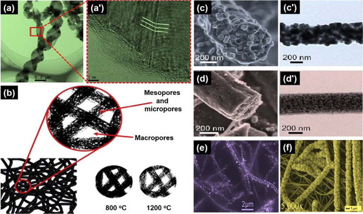
Generally two approaches have been adopted to fabricate carbon nanofibers (CNFs): vapor growth and electrospinning methods (Figs. 1a and a') [3]. In the thermal growth method, the carbon fibers are fabricated through catalytic decomposition of certain hydrocarbons in the presence of catalysts (metal particles), but this method entails great difficulties for the mass-production of CNFs. Besides this, other conventional preparation methods for CNFs are also recognized to be very complicated and overpriced, including the spraying method, substrate method, and plasmaenhanced chemical vapor deposition method [4]. Therefore, a simple and low-cost electrospinning method, first patented by Cooley [5] in 1902, has gained a lot of attention during the last decade as the optimum method to produce continuous CNFs.
2. Electrospinning: a Useful Tool to Fabricate CNFs
Recently, electrospinning has emerged as a powerful and highly versatile technique which allows micro- and nano-scale fibers to be fabricated from process polymeric solutions or melts using an electrically forced fluid jet [6]. Electrospinning shares the characteristics of both electrospraying and conventional solution dry spinning of fibers, and that makes the process particularly suited to the production of fibers using large and complex molecules on a multi-scale [7-10]. The right combination of electrospinning of organic polymers and subsequent thermal treatment in an inert atmosphere could lead to the mass production of CNFs. The fabrication of electrospun CNFs generally includes stabilization, carbonization, and sometimes graphitization, which is similar to the conventional processes for fabricating micrometre-sized carbon fibers. Depending upon the application, further physical and/or chemical activations can be used on the as-carbonized nanofibers to fabricate activated CNFs (ACNFs), which are considered to be outstanding highabsorption materials due to their excellent thermal and chemical stabilities, rapid adsorption rate, high adsorption capacity, and hydrophobicity.
Because of their peculiar structure, electrospun-based CNFs possess exceptional properties, such as nano-sized diameter, very high surface area, and thin web morphology, which make them ultra-suitable for the fabrication of high-performance nanocomposites, tissue scaffolds, sensing and energy storage devices [11]. In this review, we focus on electrospun CNFs prepared via electrospinning methods and subsequent carbonization, with a brief discussion of their structure and properties in relation to their applications. Due to the increase in research activities related to CNFs, herein we aim to present a comprehensive review on the development of electrospun CNFs fabricated using various polymeric precursors as well as their practical applications, and so reveal a complete picture of the research work in this field in the last few years.
Polymeric materials with a carbon back-bone can be used as the precursor of carbon fibers, but usually CNFs are produced from the polymeric precursors: polyacrylonitrile (PAN), cellulose, and pitch. Other precursors, such as poly(amic acid) (PAA), polyimide (PI), polybenzimidazole (PBI), poly(p-xylenetetrahydrothiophenium chloride) (PXTC), and poly(vinyl alcohol) (PVA), have also been reported. The microstructural characteristics of electrospun CNFs are extremely dependent on the physical and chemical natures of the precursor nanofibers. Therefore, controlling electrospinning conditions, like solution properties (temperature, concentration, solvent type, surface tension, and conductivity), processing parameters (applied voltage, spinneret diameter, solution flow rate, and tip to collector distance) as well as ambient conditions (relative humidity and temperature), can result in CNFs with relatively better or deteriorated performance [12].
The most common polymer for the preparation of CNFs is PAN, mainly due to its high melting point and carbon yield along with the ease of attaining thermally stabilized products. In addition, the surface of PAN-based CNFs can easily be modified using a coating or activation process [13]. Furthermore, PAN can be mixed with other polymers or be embedded with nanoscale components (nanoparticles, nanotubes, nanowires, or catalysts) to obtain multiphase precursors and subsequently to make composite CNFs. Different types of PAN-based CNFs are summarized in the following.
During the last decade, detailed researches have investigated fabricating PAN based CNFs by electrospinning [14]. Similar to the production of carbon micro fibers, CNFs have been successfully prepared by electrospinning the PAN/dimethylformamide (DMF) polymer solution followed by a two-step process: stabilization and carbonization [15]. Various stabilization and carbonization conditions have been described, in which stabilization was carried out in air at temperatures between 200-300℃ while carbonization was further performed in an inert atmosphere up to 2800℃ [16]. Progressive and multi-stage heating methods were used to reduce mass loss and dimension shrinkage. The gradual stabilization and carbonization procedure of 5℃ /min from 30-230℃, 1℃/min from 230-270℃, and then 5℃/min from 270-800℃ led to very little change in fiber packing, much less planar dimensional shrinkage, with a significant increase of carbon yield as compared to the previously reported procedure [17].
Wang
The fabrication of CNF webs, consisting of CNFs obtained through the activation of electrospun PAN-based CNFs having highly hierarchically porous structures, can lead to a significant expansion of applications of CNFs, such as in electrode materials, high-temperature filtration and the emoval of toxic gases. Steam is widely used as an activating agent for fabricating ACNFs because of its low cost and environmentally friendly characteristics (Fig. 1b). Kim and Yang [22] reported that the specific surface area of steam-ACNFs decreased with increasing activation temperature (from 700-850℃) due to the unification of micropores at elevated temperatures.
3.1.2. Composite PAN based CNFs
In order to create some functional properties in PAN-based CNFs, a variety of nanomaterials have been integrated into precursor solutions to fabricate composite CNFs by co-electrospinning and subsequent thermal treatment. High orientation of the PAN chains were induced by creating significant interactions using a thermal treatment between PAN and CNTs. The relative orientation coefficient adjacent to multi-walled CNTs (MWCNTs) in the core region of CNFs was 0.79, higher than that without CNTs, 0.44, and the relative orientation coefficient and crystallite size increased with an increase of MWCNTs concentration. At the same time, the diameter of the as-spun nanofibers could be decreased with an increase of CNTs content due to the resulting higher electrical conductivity [23]. Later, continuous single-walled CNTs (SWCNTs) were incorporated into PANbased CNF yarns using a drum as the collector. A non-graphitized structure including graphite layers and disordered carbon was formed after graphitization at 1100℃. The modulus of the stabilized SWCNT/PAN composite nanofibers was increased from 60 to 150 GPa by increasing the SWCNT content from 0-4 wt%. Although SWCNTs might protrude out of the composite CNFs due to the shrinkage of the fibers during thermal treatment, forming a rough surface, well-distributed and oriented CNTs were achieved in almost every section investigated, which is favorable for enhancing mechanical, electrical and thermal properties [24]. Positron annihilation spectroscopy is recognized as a versatile method for checking the evolution of vacancy-type flaws and their clusters in solid materials. Ra
Besides MWCNTs, other inorganic species (e.g. Ag, TiO2 and Mn) have also been added into the PAN precursor solution to prepare functional composite CNFs. PAN/Ag nanofibers were obtained, and the diameter of the CNFs varied with the Ag content from 0-5 wt%; the smallest CNFs were obtained at 1 wt%, which is in disagreement with the rule that the diameter usually increases with increasing conductivity of the solution [13]. Kim and Lim [25] investigated the physicochemical and photocatalytic activities of oxidized TiO2-embedded PAN-based CNFs(Ox-TiO2/CNF). Brunauer-Emmett-Teller (BET) specific surface area of the Ox-TiO2/CNF exhibited a large increase, from 42-223 m2 g-1 after post-oxidization, due to the loss of carbon in gaseous form [25]. Oh
The surface modification techniques applied to electrospun CNFs can combine the advantages of the coating materials and the large specific surface area of the nanofibrous substrate to provide composite CNFs with more features. Polypyrrole (PPy) was coated on as-obtained PAN-based ACNFs, which were embedded with 5.7 wt% MWCNTs [29]. A three-dimensional (3D) network of PPy particles was well organized on the surface of the ACNFs/MWCNTs. Specific surface area, mesopore volume, total pore volume, average pore size, and electrical conductivity were all increased after the incorporation of the MWCNTs in the ACNFs. Unlike previous studies which used carbonization prior to surface coating, Shao
Pitch, another precursor used to fabricate CNFs, is generally obtained from petroleum asphalt, coal tar, and poly(vinyl chloride), and has a higher carbon yield and a lower cost compared to PAN [32,33]. However, impurities in the pitch must be fully removed to obtain high-performance carbon fibers, leading to a great increase in cost. Park
PVA, another thermoplastic polymer, is a water-soluble polyhydroxy polymer and has been used as a carbon precursor in fundamental researches, even though it easily decomposes at a high temperature and gives a low carbon yield. Zhu
Unlike these thermoplastic precursors, electrospun thermosetting nanofibers like PI can directly undergo carbonization for the fabrication of CNFs without the need of the expensive stabilization process, and have thus gained increasing attention in recent years [37-39]. Kim
Aside from PI as a precursor, a series of investigations of PBI-based CNFs and ACNFs were conducted by Kim and coworkers [42]. The electrical conductivity of PBI-based CNFs showed a steady increase from 5.74 × 10⁻³ to 35 S cm-1 as the carbonization temperature was increased from 700-3000℃. The major reason might be the rigid-chain structure possessed by PBI. Even though the PBI-based CNFs treated at 3000℃ are still non-graphitizable carbons, as proved by X-ray diffraction, Raman spectra indicated a very high degree of graphitization. BET surface area kept on increasing with increasing temperature to 800℃ and then decreased if electrospun PBI was further heated to 850℃. This trend is different from PAN-based CNFs, which showed a steady decrease in the same temperature range.
Aligned nanofiber yarn several centimeters long was obtained by electrospinning another thermosetting polymer precursor (PXTC) [43]. The formation of the yarn might result from the ionic conduction of PXTC. The presence of D and G peaks in the Raman spectra signaled a successful change from electrospun PXTC yarn to CNFs in the temperature range from 600-1000℃; yarn carbonized at 500℃ did not show these two peaks in the Raman spectra. The mole fraction of graphite for the carbonized nanofibers was determined to be 0.21-0.24.
4. Applications of Electrospun CNFs
Advanced energy conversion and storage systems, like supercapacitors, rechargeable lithium-ion batteries (LIBs), and fuel cells, are in urgent demand to fulfil newly emerging applications such as portable electronics, electric vehicles, and industrial power management. The performance of these devices strongly depends on the properties of the electrode materials used. CNFs have advantages similar to a 1D carbon nanostructure with the additional benefits of being inexpensive, continuous, and relatively easy to use in applications.
4.1. Electrode materials for electrochemical capacitors
Porous carbon materials are essential for electrodes materials for electrochemical capacitors; in commercially available capacitors, activated carbons are commonly used. Iijima and Ichihashi [44] first used webs of PAN-based CNFs as electrodes of electric double-layer capacitors, using 30 wt% potassium hydroxide (KOH) aqueous solution. The 700℃ activated webs gave a very high capacitance of 173 F g-1 at a low discharge current density, as low as 10 mA g-1, but at the higher current density of 1000 mA g-1 the 800℃ activated webs gave a high capacitance of 120 F g-1. They reported that the former had a surface area of 1230 m2 g-1 containing micropores, but the latter had a surface area of 850 m2 g-1 consisting of mesopores. Similar results were obtained in later works [45,46]. PAN-based CNFs prepared by mixing PAN with 15 wt% cellulose acetate gave surface areas of 919 m2 g-1 and 241 m2 g-1, and therefore showed a capacitance of 245 F g-1 with a current density of 1 mA cm-2 [47].
MWCNTs dispersed in CNFs have given improved electric double-layer capacitor performance in aqueous electrolytes. The addition of 3 wt% MWCNTs in PAN precursor increased the surface area to 1170 m2 g-1 and electrical conductivity to 0.98 S cm-1, and consequently increased electrical double-layer capacitor capacitance to 180 F g-1 in 6 M KOH [29]. A coating of polypyrole (PPy) on these MWCNT-embedded CNFs led to a further rise in capacitance, to 333 F g-1. For MWCNT-embedded CNFs, electrical conductivity and capacitance increased to 5.32 S cm-1 and 310 F g-1, respectively, from 0.86 S cm-1 and 170 F g-1 for the nanofibers without MWCNTs [48]. Composite CNFs containing V2O5 prepared via electrospinning revealed that the content of V2O5 was the major factor responsible for the morphology and pore structures [49]. An electrode made of these C/ V2O5 composite nanofibers led to the highest specific capacitance of 150 F g-1 and energy density of 18.8 W h kg-1 over a power density range of 400-20 000 W kg-1. In another report, boric acid (H3BO3) and urea were used to introduce boron and nitrogen functional groups in CNFs and to increase total surface area [50]. The electrode with these characteristics demonstrated better supercapacitor performances, with specific capacitance of 180 F g-1 and energy density of 17.2-23.5 W h kg-1 in the power density range of 400-10 000 W kg-1.
Continuous graphene-embedded CNFs were fabricated by electrospinning PAN-DMF solution with oxidized graphene nanosheets followed by carbonization at 800℃. The electrochemical measurements revealed the maximum specific capacitance of 263.7 F g-1 in 6 M KOH aqueous electrolyte [51]. Similar graphene-integrated CNFs were prepared by using graphene in PAN/poly(methyl methacrylate) (PMMA) or PAN/TEOS [52]. Hierarchical pore structures with ultramicropores and mesopores were introduced and the supercapacitors made with these porous CNFs exhibited specific capacitance up to 150 F g-1 and energy density up to 75 W h kg-1, respectively. Higher PAN crystallinity in precursor solution has been reported to be unfavorable to the cyclization step in PAN stabilization, producing a less uniform microstructure. To reduce PAN crystallinity and to improve cyclization reaction, 9 wt% vinylimidazole was introduced to PAN molecules through copolymerization. The obtained CNFs were further activated and consequently reached a high surface area of 1120 m2/g. These CNFs were employed as electrodes for coin cell supercapacitors and presented specific capacitances up to 122 F g-1, and maximum energy and power densities of 47.4 W h kg-1 and 7.2 kW kg-1, respectively [53]. Recently, Yun
4.2. Electrode material for dye-sensitized solar cells
One-dimensional CNFs were prepared and used as a lowcost alternative to platinum counter electrodes in dye-sensitized solar cells (DSSCs) [58,59]. Electrochemical measurements revealed that the counter electrode made with CNFs exhibited low charge-transfer resistance, large surface area, and fast reaction rates in DSSCs applications. A counter electrode made of Pt/ CNFs was developed by solution-depositing Pt nanoparticles onto CNFs [60]. This type of electrode reduced the overall series resistance, decreased dark saturation current density, and the increased shunt resistance of the DSSCs. Correspondingly the Pt/CNFs-based DSCs achieved an energy conversion efficiency of ~8%, which was improved over those of pure Pt- or pure CNFs-based DSSCs. In another research, MWCNT embedded mesoporous CNFs were prepared followed by consecutive stabilization at 280℃, and carbonization at 800℃. A cell using the prepared MWCNT-embedded mesoporous CNFs as a counter electrode material exhibited even higher overall energy conversion efficiency than that of the cell using a Pt counter electrode material [61]. Recently, Park
4.3. Anode materials for lithium-ion rechargeable batteries
LIBs are attractive power sources for a wide range of electric devices from cell phones and laptop computers to hybrid electric vehicles. Kim
Electrospun CNFs anodes loaded with transition-metal oxide nanoparticles have been widely investigated as anode materials in lithium ion batteries, because of their high theoretical capacities, safety, non-toxicity and low cost [66]. One example is the fabrication of C/SnO2 composite nanofibers with adjustable sheath thicknesses, involving the electrodeposition of SnO2 on CNFs [67]. These composite nanofibrous anodes have delivered nearly 800 mA h g-1 discharge capacity at the first cycle at 50 mA g-1 current rate, with 69% capacity retention even after 100 charge/discharge cycles, reflecting a major improvement over pure SnO2 powderbased anodes [68]. Recently Kong
Because of their ultra-high specific surface area, excellent electrical properties, very high chemical resistance, and acceptable mechanical properties, electrospun CNFs are materials of choice for catalytic support. For example, CNFs were developed as an electrode support for redox enzymes immobilization which is applied in bioelectrocatalytic O2 reduction. The valuable effects of these CNFs on the electrical performance of the electrode were attributed to the high loading of active enzymes and fast kinetics at the electrode surface [71]. Without any other catalyst, the porous CNFs showed high activities for nitrogen oxide (NO) removal at room temperature. In this case, carbon acted both as catalyst and adsorbent which enabled the catalytic oxidation of NO into NO2 or the reduction of NO into N2 [72]. Recently Zhang
4.5. Sensors
Sensors/detectors with suitable operation, simple construction, steady response, high sensitivity, with good selectivity are always required for the determination of various chemicals and biomolecules. CNFs modified carbon paste electrode (CNF CPE) was developed by casting a water suspension of CNFs onto the surface of a CPE and such electrodes were used to directly detect the three amino acids l-tryptophan, l-tyrosine, and l-cysteine using cyclic voltammetry and constant potential amperometric methods [78]. The modified electrodes have shown excellent electrocatalytic activity and good analytical performance toward the oxidation of amino acids with a detection limit of 0.1 μM. CNF-CPE was also used to build an amperometric sensor device without any enzyme or medium to detect xanthine (Xa) [79]. The dynamic linear range of Xa detection was 0.03 to 21.19 μM with a detection limit as low as 20 nM. The system was effectively applied to estimate the freshness of fish and determine Xa in human urine. Recently, Hood
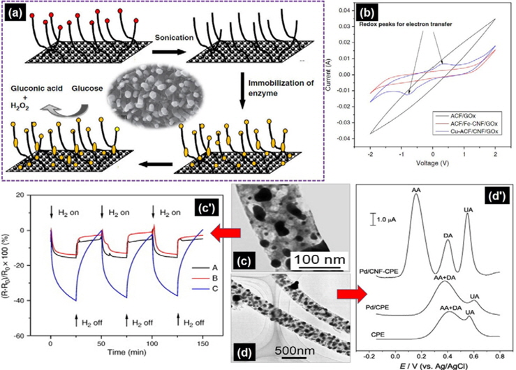
For bio sensing applications, carboxylic acid group functionalized CNFs were combined with other nanostructures to fabricate composite electrodes, and then used to incorporate hydroxyapatite (HA) or prussian blue to make a composite. These composites were coated on a polished Au electrode followed by immobilization of cytochrome c. The resulting biosensor established a good electrocatalytic activity and fast response to H2O2 sensing, with a detection limit of 0.3 μM [81]. Beside pure CNFs, metal nanoparticle-loaded CNFs could also be used to modify electrodes; for example, Pd nanoparticle-loaded-loaded CNFs was used to coat CPE (Figs. 5d and d') [55]. The as-modified electrode exhibited excellent electrochemical catalytic activities toward dopamine (DA), uric acid (UA), and ascorbic acid (AA), which frequently coexist in biological samples, by decreasing their oxidation overpotentials and improving their peak currents. The lowest detection limits of DA, UA, and AA were observed at 0.2, 0.7, 15 μM, respectively. Similarly rhodium nanoparticleloaded CNFs were dispersed in DMF under ultrasonic agitation and then cast on the surface of a pretreated pyrolytic graphite electrode. The as-modified electrode established excellent electrocatalytic activity toward hydrazine oxidation [82]. In a more recent research, a cobalt nanoparticles-decorated CNFs modified electrode showed a pH-controlled electrocatalytic activity toward the oxidation of cysteine and N-acetyl cysteine, which was used to fabricate an enzymeless sensor for amino acid [83].
In addition to the electrochemical detection of chemicals, CNFs can detect gases through resistance change. Ultrafine CNFs decorated with ZnO/SnO2 nanoparticles were deposited on an interdigitated electrode array and constructed to detect dimethyl methylphosphonate with a minimum detectable level of 0.1 ppb [84]. Recently, CNFs attached with Pd nanoparticles have shown excellent hydrogen sensing capability at room tem-perature [85]. Pd nanoparticles could be alternatively deposited on CNFs via supercritical CO2 method for the sensing of hydrogen (Figs. 5c and c') [86].
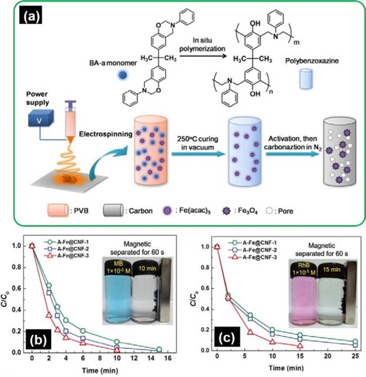
Carbon materials, particularly activated carbons, have been used as a powerful adsorbent for a long time [87-89]. Lee
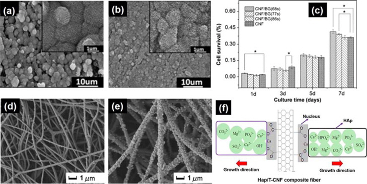
The application of carbon fibers in the biomedical field has a history of more than 30 years to date [93,94]. CNFs containing β-tricalcium phosphate nanoparticles have shown good biocompatibility for cell growth [95]. The results indicated that bioactive HA strongly interacted with the CNFs through coordination bonds and would provide strong interfacial bonding to host tissues. Fracture strength of the CNFs/HA composite reached 67.3 MPa with 41.3% CNFs. Bioactive glass (BG) is a bioceramic that has been investigated for applications in bone regeneration. CNFs with BG were developed as a substrate for bone regeneration uses. Biomineralization in simulated body fluid and in vitro co-culture with MC3T3-E1 osteoblasts revealed the improved ability of CNFs/BG composites to promote the in vitro formation of apatite and MC3T3-E1 proliferation (Figs. 7a-c) [96]. Natural bone is a fiber-reinforced hybrid material composed of type-I collagen fibers and HA minerals. CNFs were also used to prepare a CNFs/HA composite to mimic the collagen fiber/HA composite structure of natural bone (Figs. 7d-f) [56]. The fracture strength of the CNF/HA composite with a CNF content of 41.3% reached 67.3 MPa. CNF/HA composites with such strong interfacial bonding and high mechanical strength can be potentially useful in the field of bone tissue engineering.
5. Concluding Remarks and Future Perspectives
CNFs having diameters intermediate between CNTs and carbon fibers with hierarchical pore structures can be conveniently fabricated by electrospinning polymeric precursors followed by stabilization and carbonization. This new class of carbon nanomaterial with 1D nanostructure and associated high specific surface area has rapidly found application in energy conversion and storage, catalysis, sensor, adsorption, and biomedical fields. However, few studies have focused on the stretching of electrospun precursor nanofibers before stabilization, and tension is rarely applied to the nanofibers assembly during stabilization to prevent shrinkage of the fibers and to ensure a large degree of molecular orientations along the fiber axis. Therefore, there is still considerable room for further improvement of the microstructural, electrical and mechanical properties of the final CNFs. Current attempts reveal there is a strong expectation of achieving even higher strength carbon fibers. Future research will be focused on the fundamental correlations between processing conditions and the nanofibers’ structures and it is envisioned that electrospun continuous CNFs are going to contribute greatly to the emerging family of carbon materials.

![Transmission electron microscope (TEM) image of (a) carbon nanofibers (CNFs) with twisting nanoribbon and (a') high-resolution TEM (HRTEM) image of twisting nanoribbon. (b) Scheme showing the hierarchical structure of CNFs. (c) Scanning electron microscope (SEM) and (c') TEM image of SnCo/ polyvinylpyrrolidone-CNFs. (d) SEM and (d') TEM image of SnCo/polyacrylonitrile-CNFs. SEM images (e) of the Pd/CNF-carbon paste electrode surface and (f ) growth of hydroxyapatite on P-CNF. (a-a') Reprinted with permission from [3]. Copyright ⓒ 2013, Authors. (b) Reprinted with permission from [54]. Copyright ⓒ 2013, Elsevier. (c-d') Reprinted with permission from [31]. Copyright ⓒ 2013, American Chemical Society. (e) Reprinted with permission from [55]. Copyright ⓒ 2008, Elsevier. (f ) Reprinted with permission from [56]. Copyright ⓒ 2013, Elsevier.](http://oak.go.kr/repository/journal/13510/HGTSB6_2014_v15n1_1_f001.jpg)
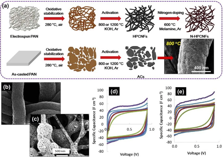
![(a) Scheme for the processing of activated carbons (ACs), hierarchically porous carbon nanofibers (CNFs), and nitrogen-doped hierarchically porous CNFs. Scanning electron microscope micrographs of porous CNFs formed by carbonizing nanofibers at different Nafion:polyacrylonitrile (PAN) blend compositions: (b) 80:20 electrospun at 25% total solid concentration, (c) 80:20 electrospun at 20% total solid concentration. Cyclic voltammetry of (d) carbonized 60:40 Nafion:PAN and (e) carbonized 80:20 Nafion:PAN. (a) Reprinted with permission from [54]. Copyright ⓒ 2013, Elsevier. (b-e) Reprinted with permission from [57]. Copyright ⓒ 2013, Elsevier.](http://oak.go.kr/repository/journal/13510/HGTSB6_2014_v15n1_1_f002.jpg)
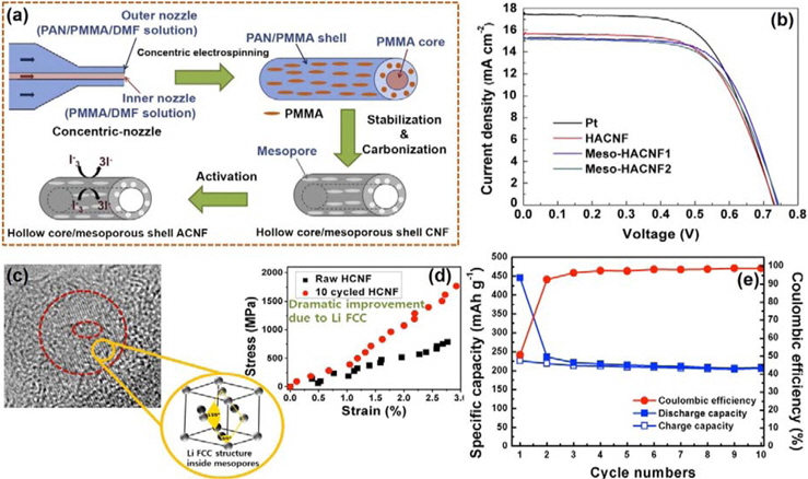
![(a) The fabricating process and I-3 reduction of activated carbon nanofibers (ACNFs) with hollow core/mesoporous shell structure. (b) I-V curves of hollow ACNF (HACNF), Meso-HACNF1, Meso-HACNF2, and Pt counter electrode. (c) High-resolution transmission electron microscope images of donutshaped lithium face centered cubic (FCC) metal crystallites and (d) stress-strain curves of hollow CNF (HCNF). (e) Cycling performances of freestanding HCNF anodes. (a and b) Reprinted with permission from [59]. Copyright ⓒ 2013, Elsevier. (c-e) Reprinted with permission from [70]. Copyright ⓒ 2013, American Chemical Society.](http://oak.go.kr/repository/journal/13510/HGTSB6_2014_v15n1_1_f003.jpg)
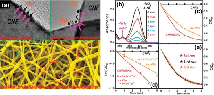
![(a) Schematic illustration of carbon nanofibers (CNFs)@Au as an electron-rich platform including the interface and cross-linked network. Catalytic performance of the CNFs@Au network. (b) UV-vis absorption spectra during the catalytic reduction of 4-nanoparticle over the CNFs@Au; (c and d) C/C0 and ln(C/C0) versus reaction times for the reduction of 4-nanoparticle, CNFs (squares), Au nanoparticles (circles) and CNFs@Au (stars); (e) catalytic activity of the CNFs@Au network for the reduction of 4-nanoparticle after three rounds of cycling. (a-e) Reprinted with permission from [73]. Copyright ⓒ 2013, Royal Society of Chemistry.](http://oak.go.kr/repository/journal/13510/HGTSB6_2014_v15n1_1_f004.jpg)
![(a) Schematic of the proposed bimetal carbon nanofibers (CNF)-based electrode for glucose biosensor. (b) CV of activated CF (ACF)/GOx, ACF/Fe-CNF/GOx, and Cu-ACF/CNF/GOx in the presence of 2 mM glucose (scan rate = 100 mV/s). Transmission electron microscope (TEM) image of the as-prepared (c) Pd/CNF nanocomposites and (c') response curves of different carbon nano-felts upon exposure to H2 at room temperature. (d) TEM image of ASFPAN-PdNP and (d’) DPVs at bare carbon paste electrode (CPE), Pd/CPE and Pd/CNF-CPE in 0.1 M PBS (pH 4.5) containing 2 mM ascorbic acid, 50 μM dopamine and 100 μM uric acid. (a and b) Reprinted with permission from [80]. Copyright ⓒ 2013, Elsevier. (c and c') Reprinted with permission from [86]. Copyright ⓒ 2012, Elsevier. (d and d') Reprinted with permission from [55]. Copyright ⓒ 2008, Elsevier.](http://oak.go.kr/repository/journal/13510/HGTSB6_2014_v15n1_1_f005.jpg)
![(a) Illustration showing the synthesis of A-Fe@carbon nanofiber (CNF) by a combination of electrospinning and in situ polymerization. The C/C0 versus time plots for adsorption of (c) methylene blue (MB) and (d) rhodamine B (RhB) dye solution. The insets show the magnetic responsive performance (60 s) of A-Fe@CNF-3 after adsorption of MB (10 min) and RhB (15 min). (a-c) Reprinted with permission from [92]. Copyright ⓒ 2012, Elsevier.](http://oak.go.kr/repository/journal/13510/HGTSB6_2014_v15n1_1_f006.jpg)
![Scanning electron microscope (SEM) micrographs obtained for the carbon nanofiber (CNF)/bioactive glass (BG) after being soaked in 1.5 SBF at 37℃ for 4 days (a) and 6 days (b). (c) Proliferation of MC3T3-E1 osteoblasts on different CNF/BG composite membranes in comparison with pure CNF assessed using CCK-8 assay. (e) SEM images of (d) 1 h-T-CNF/hydroxyapatite (HA) and (e) 6 h-T-CNF/HA, and (c) growth of HA on activated CNFs. (a-c) Reprinted with permission from [96]. Copyright ⓒ 2013, Elsevier. (d-f ) Reprinted with permission from [58]. Copyright ⓒ 2013, Elsevier.](http://oak.go.kr/repository/journal/13510/HGTSB6_2014_v15n1_1_f007.jpg)