Carbon/carbon (C/C) composites are advanced materials comprising carbon fiber (CF) as a reinforcement and derived carbon as a matrix. They were first synthesized in the 1970s [1] and since have been diversified for various applications on the basis of their versatility in tailoring their properties. They are used in the manufacture of heat sinks [2,3], and in thermal assemblies and as brake discs of airplanes and military vehicles [4,5], and in reusable launch vehicles, owing to their excellent thermal properties and low coefficient of thermal expansion at higher temperatures. They have also found application in energy systems, mainly for the fabrication of bipolar plates [6], because of their high thermal and electrical conductivity. They are further used for the fabrication of International Thermonuclear Experimental Reactor (ITER) plasma facing components [7] because of their high thermal conductivity and thermal shock resistance.
Continuous CF reinforced C/C composites have been extensively studied by many researchers worldwide [8-16]. In this context, fabrication methods of pyrolytic graphite such as chemical vapor infiltration (CVI), metallurgical products’ hotisostatic pressing (HIP), and hand layup are very common and well established for making continuous C/C composites. C/C composites made through these processes have excellent properties but each process has respective limitations. C/C composites made through CVI have extremely good mechanical properties but are very costly and time consuming. On the other hand, HIP reduces the fabrication time but the product cost is very high due to huge capital costs. Other methods such as hand layup involve lesser cost but take more time. Hence, their usage is limited to high end applications such as aerospace and defense materials.
Composite systems such as randomly oriented discrete CF reinforced carbon matrix composites have been explored for rapid fabrication of C/C composites [6,17]. Notably, a randomly oriented hot-pressed C/C composite was found to be cost effective [6]. But the mechanical properties of this C/C composite are moderate due to discrete length reinforcement. However, its thermal and electrical properties are excellent [17]. Various applications where moderate mechanical properties are sufficient, such as bipolar plates, are good targets for this type of composite system.
Variants of a randomly oriented C/C composite are studied to establish a viable fabrication process. The fabrication of a hot-pressed C/C composite is rapid even then it takes quite more time, because the derivation of the carbon matrix from its precursors is very slow and precise. Furthermore, fabrication of test specimens and characterization of various properties for optimization are time-consuming and costly. In this context, to reduce the optimization time and cost, morphological optimization has been explored for a discrete length hybrid CF reinforced carbon matrix composite system. It was found to be suitable in terms of fast and cost effective optimization of process parameters.
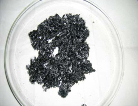
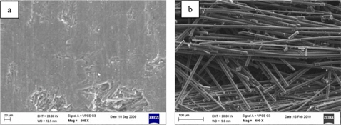
High strength polyacrylonitrile based CF T-800 and high modulus and high conductivity pitch based CF P-75 are used as reinforcement for making a randomly oriented discrete length CF reinforced carbon matrix composite. The chopped CFs are shown in Fig. 1 and the properties of the CFs are listed in Table 1. Petroleum pitch derived mesophase pitch (MP) is used as a matrix precursor for deriving the carbon matrix. The characteristics of MP are listed in Table 2. Distilled water is used as the slurry media.
[Table 1.] Properties of carbon fibers
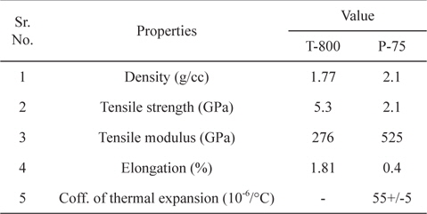
Properties of carbon fibers
[Table 2.] Properties of mesophase pitch
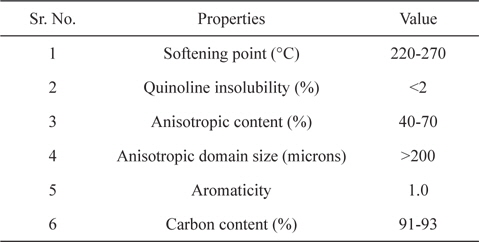
Properties of mesophase pitch
2.2. Fabrication of C/C composite
CFs are chopped into discrete length using a chopping machine. P-75 CF and T-800 CF are taken in a weight ratio of 70:30. MP is powdered to 400 mesh size. A slurry of chopped CFs and powdered MP is prepared by agitating the powdered MP and chopped CFs in distilled water for 60 min. The slurry is then vacuum moulded and dried in an air oven at 50℃. The preform thus made is hot-pressed at 650℃ for 60 min to bind the reinforcement by deriving a carbon matrix from the MP matrix precursor via pyrolysis and partial carbonization. Partial carbonization is only carried out due to the temperature limitation of the hot-press. The complete carbonization of all the compacts is done in a carbonization furnace at 1050℃ for 60 min. Pressure and heating rates are varied during hotpressing only.
Four compacts are fabricated at different hot-pressing pressures and six compacts are fabricated by varying the hot-pressing heating rate. Three compacts are fabricated by varying the matrix precursor to reinforcement weight ratio. The designations of the compacts processed at different processing conditions are given in Table 3.
[Table 3.] The designation of the compacts processed at different processing conditions
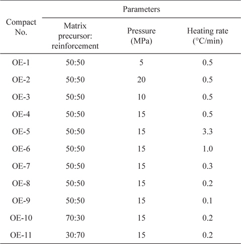
The designation of the compacts processed at different processing conditions
The structure of C/C composite samples is characterized using a Carl Zeiss SMT EVO 50 model scanning electron microscope (SEM). SEM images are taken under variable pressure using 80P air pressure. LaB6 filament is employed for taking the images. SEM images are taken only after carbonization.
The bulk density of the C/C compacts is determined after hotpressing and carbonization. It is calculated by the mass-volume formula.
Both compressive strength and flexural strength are measured using a universal testing machine (Instron 5500R standard). Flexural strength and compressive strength are tested according to ASTM C 1161-02C and ASTM C 695-91 (Reapproved 2005), respectively. Optimum dimensions of test specimens for a bending test and a compression test are assumed as 3 mm × 4 mm × 45 mm and 9 mm × 9 mm × 18 mm, respectively. Both flexural strength and compressive strength are tested in the inplane direction.
Initially, the matrix precursor to reinforcement weight ratio is selected as 50:50. The heating rate is taken 0.5℃/min. Keeping these variables constant, the pressure is then varied. Table 4 shows the influence of hot-pressing pressure on the densification and microstructure of the compacts. In the first attempt, a very low pressure of 5 MPa is imparted to the compact (OE- 1) through the piston assembly of the hot-press. This pressure failed to result in a compact with adequate integrity. In the second attempt, half of the maximum possible pressure (40 MPa) of the hot-press is applied (i.e. 20 MPa) to the compact (OE-2). Under this pressure, a huge amount of molten matrix precursor along with discrete CFs extrudes through the gap that is maintained between the male and female parts of the die, leading to a smooth escape of the hetro-atoms. This is not very high pressure for oozing. Note that various researchers have fabricated C/C composites by deriving a carbon matrix from MP at very high pressure of up to 100 MPa [18]. However, this type of operation has been done in HIP. Since pressure is imparted to the compact isostatically in HIP process, oozing does not take place. In the hot-press method, high pressure without oozing of the matrix precursor can be imparted to the compact on account of the gap between the male and female parts of the die. When the gap is reduced, smooth liberation of hetro-atoms is impeded. Due to this, bloating is observed in compacts even after processing at higher pressure [6]. Hence, for an optimum gap with respect to smooth liberation of hetro-atoms, a pressure of 20 MPa or higher results in oozing of the MP matrix precursor and discrete CFs.
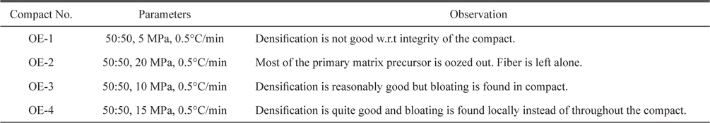
Influence of hot-pressing pressure on the densification and microstructure of the compacts
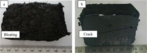
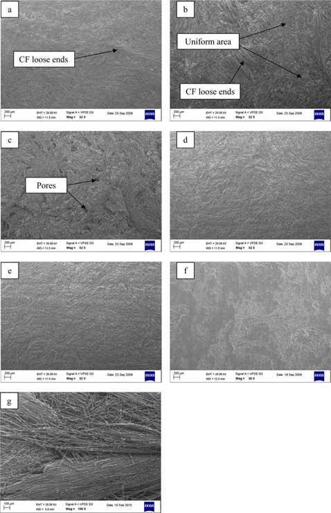
In the third attempt, 10 MPa pressure is imparted to the compact (OE-3). Reasonably good densification of the compact with good macroscopic integrity is observed. Density of 0.69 and 0.63 g/cc is achieved after hot-pressing and carbonization, respectively. A marginal decrease in density after carbonization occurred due to liberation of remaining hetro-atoms at elevated temperature [6]. Microstructural observation of the compact OE-3 is carried out under a scanning electron microscope. The compact OE-3 shows bloating (Fig. 2a) on the surface, indicated by the absence of the matrix on and between CFs present on the surface. The loose bonding of CF ends and the absence of matrix on the surface resulted in the bloating.
In the fourth attempt, pressure of 15 MPa is imparted to the compact (OE-4). Very good densification of the compact is observed. The density is increased from 0.69 to 0.75 g/cc (or 8.69%) after hot-pressing as pressure is increased from 10 to 15 MPa. In this compact the density also decreased marginally after carbonization as a result of liberation of remaining hetro-atoms at elevated temperature. The compact has excellent macroscopic integrity. A micrograph (Fig. 2b) of the compact OE-4 reveals localized bloating. Compared to compact OE-3, fewer CFs are loosened and devoid of carbon matrix. This indicates that 15 MPa compaction pressure is optimum to obtain a compact with good densification and a reasonably good microstructure.
To validate the morphological analysis results, compressive strength and flexural strength of the compacts OE-3 and OE-4 are tested. Compressive strength of 21 MPa and flexural strength of 15 MPa are obtained for compact OE-3. The presence of bloating on the surface and inside the compact caused degradation of mechanical properties. The mechanical properties are slightly improved in the case of compact OE-4 as compared to compact OE-3. Compressive strength increased from 21 to 25 MPa (19.04%) and flexural strength increased from 15 to 17 MPa (13.33%). This is ascribed to transformation of uniform and severe bloating into localized bloating.
3.2. Heating rate optimization
The matrix precursor to reinforcement weight ratio is again fixed to 50:50 weight %. Optimized pressure of 15 MPa is applied. Under these values of pressure and matrix precursor to reinforcement weight ratio, the heating rate is varied to study its effect on the densification and microstructure. Table 5 shows the influence of the heating rate on the densification and microstructure of the compacts.
[Table 5.] Influence of heating rate on the densification and microstructure of the compacts
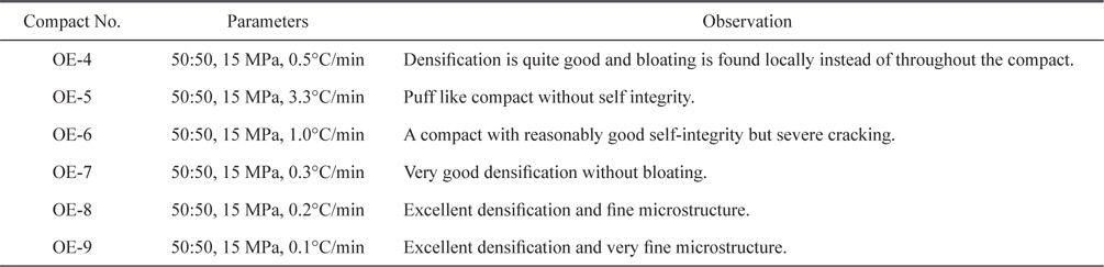
Influence of heating rate on the densification and microstructure of the compacts
From pressure optimization experiments, i.e. OE-1, OE-2, OE- 3, and OE-4, it is seen that two compacts, OE-3 and OE-4, have reasonably good densification but micro-bloating is seen in both compacts. Further improvement of the densification without bloating can be achieved either by varying the heating rate or the matrix precursor to reinforcement weight ratio. In this regard, two heating rates above 0.5℃/min are initially chosen to study its influence on densification and microstructure of the compacts. In the first attempt, a heating rate of 3.3℃/min is applied. The compact OE-5 is fabricated at this heating rate. After hot-pressing, the compact lacks integrity and has a puffy appearance (Fig. 3a) after hot-pressing. It is then fragmented upon carbonization at 1050℃.
In the second attempt, heating rate is reduced to 1.0℃/min. Fig. 3b shows the compact OE-6 that is hot-pressed at 1.0℃/ min. It can be clearly seen that the hot-pressed compact OE-6 has a good shape compared to the hot-pressed compact OE-5 (Fig. 3a). But various cracks exist on the surface and sides of the compact. The density of the compact after hot-pressing is 0.70 g/cc. The density of the hot-pressed compact OE-6 is minutely higher than that of the hot-pressed compact OE-4. However, it is broken into pieces upon carbonization. This is ascribed to preexisting cracks. Overall, both compacts OE-5 and OE-6 have poor self integrity. The compact OE-4, which is hot-pressed at similar pressure and matrix precursor to reinforcement weight ratio to that of compacts OE-5 and OE-6 but at lower heating rate, i.e. 0.5℃/min, has excellent integrity without any cracks, in contrast to these two compacts. However, it has localized micro-bloating. A comparative analysis of these three compacts, i.e. OE-4, OE-5, and OE-6, shows that the cracks and microbloating reduce when the heating rate is decreased. Further decrease of the heating rate may result in better densification without bloating. This trend is associated with pyrolysis of the matrix precursor, i.e. MP. MP comprises various hydrocarbons. These hydrocarbons upon pyrolysis and subsequent carbonization release non-carbonaceous matter in the form of volatiles, i.e. hydrogen, nitrogen, water, carbon dioxide, etc. Hence, the liberation rate of these volatiles plays a pivotal role in the fabrication of a C/C composite with good integrity and densification. A higher liberation rate raises the likelihood of bloating [6].
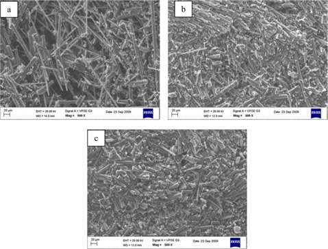
In the third attempt, the heating rate is reduced to 0.3℃/min. Figs. 2c and 4a show the microstructure of compact OE-7, which is hot-pressed at 0.3℃/min. SEM observation of the compact OE-7 reveals a uniform microstructure with the absence of bloating. CF ends on the compact surface are almost bonded with the matrix, and indicate the critical heating rate to process the compact without bloating. In this compact, bulk loose ends of CFs are not observed. However, holes exist throughout the surface of the compact (Fig. 2c). The hot-pressed density of the compact OE-7 is increased to 1.04 g/cc compared with compacts OE-3, OE-4, and OE-6, where the hot pressed density obtained is 0.69, 0.75, and 0.70 g/cc, respectively. In this compact a marginal decrease of the density after carbonization is recorded.
In the fourth attempt, the heating rate is further reduced to 0.2℃/ min. Under this rate, the processing time of compact OE-8 is increased by 28.57% compared to compact OE-7. SEM micrographs (Figs. 2d and 4b) of compact OE-8 reveal a microstructure that is devoid of loose CF ends on the surface of the compact with localized porosity. The hot-pressed density is increased from 1.04 to 1.51 g/cc (45.19%) as the heating rate is decreased from 0.3 to 0.2℃/ min. The density after carbonization is decreased by 4.64%. This again is due to liberation of hetro-atoms at elevated temperature. The tremendous increase in the hot-pressed density of the compact OE-8 compared to compact OE-7 is ascribed to transformation of surface holes (Fig. 2c) into a fine structure (Fig. 2d) due to smooth liberation of hetro-atoms as a result of the low heating rate.
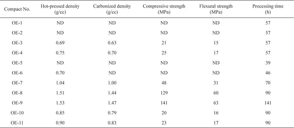
[Table 6.] The density and mechanical properties of the compacts

The density and mechanical properties of the compacts
In the fifth attempt, the heating rate is reduced to 0.1℃/min. Under this rate, the processing time is increased by 55.56% and 100% compared to compacts OE-8 and OE-7, respectively. Figs. 2e and 4c show micrographs of compact OE-9. It can be seen from these figures that compact OE-9 neither contains any loose CF ends on the surface nor localized porosity. However, compact OE-9 indicates very fine morphology with good CF to matrix bonding. The increase in the density of compact OE-9 compared to compact OE-8 is very slight, i.e. 1.3%. However, the processing time is more than one and half times greater. Hence, microstructure analysis of compacts OE-5 to OE-9 w.r.t. bloating free densification and economics shows that the compact hot-pressed at 0.2℃/min is the most applicable.
Validation of the morphological analysis of heating rate is done by testing the compressive strength and flexural strength of compacts OE-7 to OE-9. Compressive strength of 48 MPa and flexural strength of 31 MPa are obtained for compact OE-7. The compressive strength and flexural strength of compact OE-7 are greater than those of compact OE-4. The absence of bloating in compact OE-7 compared to compact OE-4 resulted in improved mechanical properties. The mechanical properties are improved considerably with compressive strengths of 129 and 141 MPa and flexural strengths of 60 and 63 MPa for compacts OE-8 and compact OE-9, respectively. This dramatic increase in the mechanical properties of compacts OE-8 and OE-9 compared to compact OE-7 is attributed to low open porosity, which is a result of higher densification.
3.3. Matrix precursor to reinforcement ratio optimization
Compact OE-8 processed at heating rate and pressure of 0.2℃/min and 15 MPa, respectively, shows a microstructure without bloating or localized porosity. These heating rate and pressure values are hence optimized to study the effect of the matrix precursor to reinforcement weight ratio on the densification and microstructure of the compacts. Table 7 shows the influence of the matrix precursor to reinforcement weight ratio on the densification and microstructure of the compacts. In the first attempt, compact OE-10 with a matrix precursor to reinforcement weight ratio of 70:30 is fabricated. Figs. 2f and 5a show micrographs of compact OE-10. It can be seen clearly that the surface is completely covered with the carbon matrix, which is derived from matrix precursor. Hardly any CFs are visible on the compact surface. This indicates that the amount of matrix precursor exceeds the required amount to form a uniform compact. Hot-pressed density of 0.85 g/cc is obtained for compact OE-10. This is substantially less than the achieved hot-pressed density of compact OE-8, which is hot-pressed at the same hot-pressing rate (0.2℃ and 15 MPa).
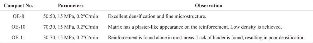
Influence of matrix precursor to reinforcement weight ratio on the densification and microstructure of the compacts
In the second attempt, compact OE-11 with a 30:70 matrix precursor to reinforcement weight ratio is fabricated. Micrographs (Figs. 2g and 5b) of the compact reveal loosely bonded CFs on the surface. Very little carbon matrix is visible on the surface of the CFs and a greater gap exists between the filaments. This indicates that the quantity of the matrix precursor is not enough to yield a sufficient amount of carbon matrix to bind the CF reinforcement. Hot-pressed density of 0.90 g/cc is obtained for compact OE-11. The density after carbonization is marginally decreased for both compacts OE-10 and OE-11. This is due to liberation of remaining hetro atoms at carbonization temperature. The hot-pressed density of compact OE-11 is marginally improved (5.88%) compared to compact OE-10. However, it is again much less than the achieved hot-pressed density of compact OE-8. This lower value of the density compared to compact OE-8 is due to a lack of matrix to bind the CFs together. A comparative analysis of compacts OE-8, OE-10, and OE-11 shows that a matrix precursor to reinforcement weight ratio of 50:50 is optimum for this composite system w.r.t. densification and microstructure.
As with the hot-pressing pressure and rate, the morphological analysis of the matrix precursor to reinforcement weight ratio is validated by testing the compressive strength and flexural strength. Compact OE-10 yielded compressive strength of 20 MPa and flexural strength of 16 MPa. This is attributed to a smaller amount of CF reinforcement than the critical amount. Similarly, compact OE-11 yielded lower strength. Compressive strength of 23 MPa and flexural strength of 17 MPa were achieved for this compact. These poor values are due to a lack of binding because of the smaller amount of matrix precursor.
A randomly oriented discrete length hybrid CF reinforced derived carbon matrix composite is fabricated. Morphological observation of the fabricated compacts by scanning electron microscopy provides insight into the CF to carbon matrix bond- ing, the amount of bloating represented by the presence of loose CF ends on the surface, and micro-porosity. These observations indicate changes in the microstructural details of the compacts with various processing parameters such as hot-pressing pressure and heating rate and matrix precursor to reinforcement weight ratio.
The density and the mechanical properties of the compacts are found to be strongly dependent on the microstructure of the compacts. The presence of loose CF ends, bloating, and microporosity in the microstructure leads to lower density and degradation of mechanical properties including compressive strength and flexural strength.
A morphological optimization technique of process parameters is designed and successfully demonstrated for optimization of process parameters of the reported composite system. The methodology is found to be very promising in reducing the optimization time and cost.