Microwaves are a part of the electromagnetic spectrum with frequencies ranging from 300 MHz to 300 GHz, lying between infrared and radio frequencies. Microwave technologies were developed rapidly during and after the Second World War for radar and communication uses. These days, microwaves are extensively used for wireless communications, such as long term evolution; for major wireless local area network standard (Wi-Fi); space craft communication and radar applications like global positioning system; and air traffic control. In addition to the radar and communication uses, microwaves are also widely used for heating. Foods are rapidly and conveniently heated by a microwave oven at home, and a variety of materials are heated at industries and laboratories using microwaves.
Microwave heating provides several advantages over conventional (firing or resistive) heating, most of which come from the way energy is delivered. Microwaves can deliver their energy directly to target materials by radiation at the speed of light without conduction or convection, the main processes of energy transfer in conventional heating. Thus, microwave heating is much faster than conventional heating, and selective heating is possible without interaction between the microwaves and their surroundings.
Research on the microwave heating of carbon-based materials can be classified into two categories depending on the phase of microwave absorber. One is solution heating, represented by microwave-assisted organic synthesis (MAOS) and the other is solid heating, whose main targets are solid state carbons and metals. Solution and solid heating differ greatly, both in the heating mechanism and the accompanying reactions.
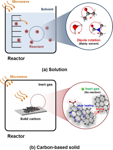
The difference in the heating mechanism for a solution and a carbon-based solid is shown in Fig. 1. Microwave heating of a solution is mainly related to the dipole rotation of polar solvent molecules. However, in electron-rich solids which have no freely-rotatable dipoles, like carbon-based solids, it is the motion of electrons that generates heat, through joule heat-ing within the grain, or arc generation at phase boundaries.
Microwave heating of solid state carbon-based materials has distinct merits, but they have scarcely been reported, while over 800 papers were published about MAOS in 2007 alone [1]. The purpose of this review is to introduce the microwave heating of carbon-based solid materials, including carbon nanotubes (CNTs), graphite, and others. Also, issues crucial to the advanced research of microwave-carbon heating are discussed.
The mechanism of microwave heating varies according to the interaction between the microwaves and target materials. In this section, the heating mechanisms and the characteristics of solution heating and carbon-based solid heating will be covered for an obvious contrast. Before that, polarization and conductivity will be dealt with, since they play important roles in the microwave heating of both solutions and carbon-based solids.
2.1. Polarizations under microwaves
When a dielectric material, whose charged particles can’t move freely, is exposed to an external electric field, the electric charges cause dielectric polarization, which arises from the displacement of charges from their average equilibrium position. This polarization can be categorized as follows: 1) electronic polarization by displacement of electrons from the nuclei, 2) atomic polarization by displacement of atomic nuclei, 3) dipolar polarization by reorientation of molecules which have permanent dipoles, and 4) interfacial polarization by accumulation of relatively mobile charges at grain/phase boundaries or surfaces.
Microwaves are a kind of electromagnetic wave, and consequently, the direction and the magnitude of their electric field changes continuously with time, so the polarization they induce is also changed with time. In general, polarization has a phase lag with the electric field oscillation because a material’s polarization does not respond instantaneously to an applied field. Therefore, permittivity (ε), which describes the electric field flux generated by polarization, is usually expressed as a complex form (ε′+iε′′) to show the magnitude and the phase of polarization at the same time. Here, the real part of permittivity (ε′) is related to the stored energy within the medium and the imaginary part of the permittivity (ε′′) is related to the energy dissipated as heat.
When the frequency of an electric field oscillation is increased over a certain point, some polarization stops contributing to the total polarization because there is an increasing phase lag between the electric field oscillation and reorientation of the polarization. In this case, the real part of the permittivity decreases while the imaginary part of the permittivity decreases, which means the dissipation of energy in the form of heat increases.
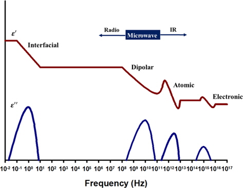
The frequency dependence of dielectric permittivity is shown in Fig. 2. Electronic polarization and atomic polarization don’t contribute to microwave absorption because they start to have phase lag at a frequency higher than the microwave frequency. Generally, interfacial polarization occurs far below the microwave frequency, but the peak frequency of dielectric loss factor of interfacial polarization can vary considerably according to the conductivity and dielectric properties of the material. Thus, interfacial polarization as well as dipolar polarization are considered to be the polarizations involved in microwave heating.
2.2 Conductivity under microwaves
When charged particles can move freely within the material, electric conduction can be generated by charged particles, which obtain kinetic energy from the external electric field. Typical examples are the movement of electrons in metals or semiconductors and the movement of ions in ionic liquids.
The movement of charged particles generates heat by collisions. Electrons collide with atomic ions composing the body of conductors or semiconductors. Ions in an aqueous solution collide with neighboring molecules or atoms. Heat is generated as a consequence of the collisions, a process commonly called Joule heating.
2.3. Microwave heating of solutions
Microwave heating of a solution is explained by dipolar polarization and ionic conduction. Most solvents including water, dimethylformamide, tetrahydrofuran and ethanol have permanent dipoles. When a microwave is applied, the dipoles rotate with a delay to the change of the electric field, which causes friction and heat. In addition, the solution is also heated by ionic conduction when ions exist.
As a result, most reactions can be carried out using polar solvents even when the microwave absorbance of the reactant is poor. On the other hand, the method has some limitations, as follows: 1) most of the microwave energy used for the heating of polar solvents is dissipated, and 2) there is no macroscopic difference in the distribution of temperature within the reactor, while the absorption of microwave energy may be selective.
2.4. Microwave heating of carbon-based solids
In the case of carbon-based solids which have few or no freely rotating dipoles, microwave heating can’t be explained as above. Instead, the interaction between microwaves and electrons is important. Microwave heating of carbon-based solids is mainly explained by interfacial polarization (so called Maxwell- Wagner-Sillars [MWS] polarization). In addition, carbon-based solids possess semiconducting features because of delocalized pi-electrons in the graphitic region [3,4], so Joule heating also plays an important role in the heating of carbon-based solids by microwave.
In these cases, unlike solution heating, microwave heating is very efficient and selective because the microwave energy is solely absorbed by the target material.
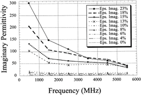
CNTs have excellent electrical properties resulting from sp2- networks of carbon atoms. The number of free electrons which can migrate freely over the whole of the layer is about one per each carbon atom [4]. The free electrons enable CNTs to absorb microwave energy considerably and to be heated effectively by microwaves.
The microwave absorbing property of CNTs was measured by Grimes
In 2003 Imholt
Among the various applications of microwave heating of CNTs, CNT/polymer welding is the most actively researched area. Unlike other CNT/polymer composite making techniques such as solution mixing, melt mixing and in-situ polymerization [16], microwave welding gives several advantages.
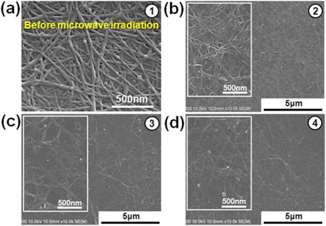
The first advantage is that microwave welding can be done within a few minutes [7-11,13-15]. Specifically, Wang
[Table 1.] Conditions and results of CNT/polymer microwave welding
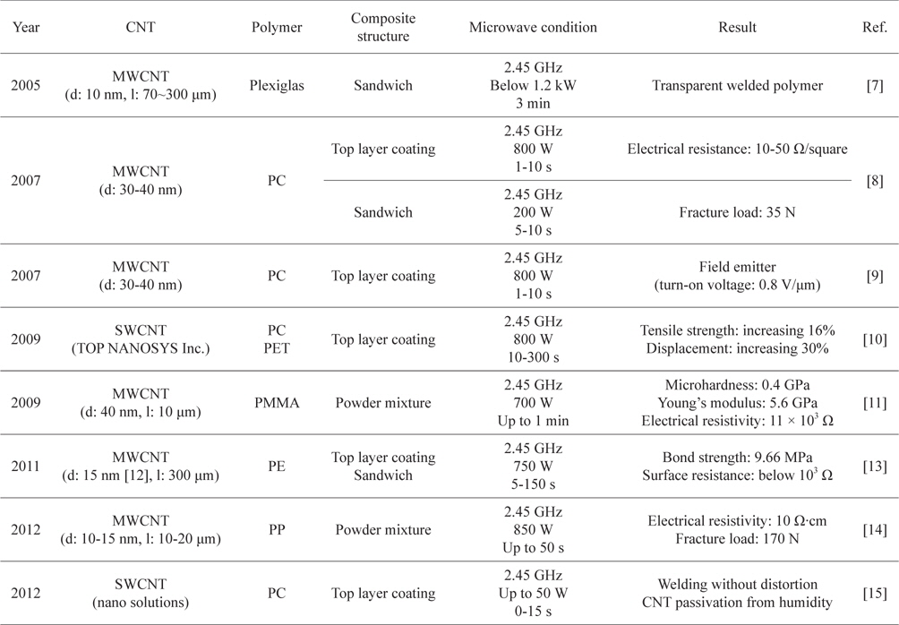
Conditions and results of CNT/polymer microwave welding
Other applications like annealing, regeneration and detection based on the microwave heating of CNTs have also been reported.
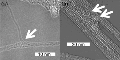
A rapid temperature elevation and nanotube reconstruction had already been reported by Imholt
Wang
Microwave heating was also used for the quantitative detection of CNTs contained in living organisms. Irin
4. Microwave Heating of Graphite
Microwave heating of graphite is mostly related to the preparation of exfoliated graphite from graphite intercalation compound (GIC). Recently, the reduction of graphite oxide (GO) also became a popular topic, with the growing interest in the mass production of graphene.
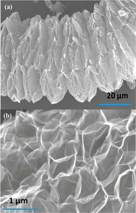
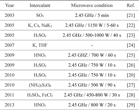
Rapid heating and the use of a pre-heated furnace are wellknown methods for the exfoliation of GIC. Recently, heating methods using the rapid heating characteristic of microwaves have been reported. (Microwave exfoliation conditions for GICs are summarized in Table 2.)The most notable features of microwave exfoliation are immediacy and effectiveness. The exfoliation is completed within a minute in most cases [23,25-29], and higher volume expansion is observed than with the conventional method using an electrical furnace at over 1000℃ [25,28] (Table 3). In addition, relatively uniform expansion [21], dry- ing effect [22], and the potential of scale-up [20] were reported. Scanning electron microscope images of microwave-exfoliated graphite by Sridhar
[Table 2.] Microwave exfoliation conditions for GICs
Microwave exfoliation conditions for GICs
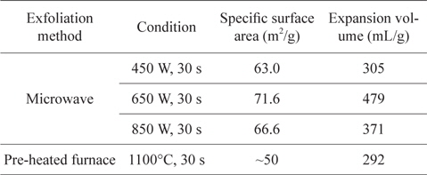
Specific surface area and expansion volume of EGs prepared by microwave irradiation and pre-heated furnace [28]
Similar to the exfoliation of GIC, the reduction of GO requires thermal annealing at over 1000℃. So, microwave heating has received attention as an efficient heating method. Li
5. Microwave Heating of Other Carbon-Based Materials
Although large and well-arranged graphitic layers rarely exist, carbon-based materials like activated carbon, carbon fiber and others contain a certain portion of graphitic parts and the portion can be increased by elevating the heat treatment temperature [33,34]. Therefore, microwave heating of these carbon-based materials is also reported.
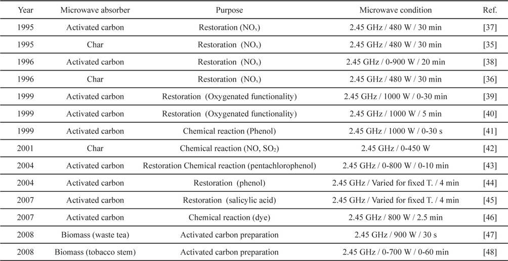
Microwave heating of activated carbon, char and biomass are mostly related with adsorbents. Restoration of NOx saturated activated carbon and char was extensively reported in the 1990s [35-38]. Microwave heating restored activated carbon and char effectively with sufficient power in several cycles. Kong and Cha [38] reported regeneration of NOx-saturated char within a minute when the input power was over 300 W. Also, Menendez
[Table 4.] Applications of microwave heating with activated carbons

Applications of microwave heating with activated carbons
Environmental approaches with a similar concept have been reported around and after 2000. Microwave irradiation of activated carbon for removing organic chemicals, dye and SO2 was tried [41-46]. Representative strengths included the short time required [41,43-46], porous structure preservability [44] and high regeneration efficiency after many cycles [45]. Recently, conversions of biomass into activated carbon through microwave heating were also reported [47,48].
In addition, Carrott
While microwave heating of relatively unordered carbons like coal or coke has been reported [51,52], follow-up studies are required for better understanding.
As mentioned in the previous sections, microwaves can be a powerful tool for the heating of carbon-based materials, and thus various applications have been reported, though deeper understanding of the heating mechanism is still required for advanced and systematic research. Some of the key issues for the development of microwave heating of carbon-based materials are covered in this section.
Antenna theory, which is related to radar or communication, and polarization, which is related to solution heating with microwaves, have been studied relatively well [1,53]. In the case of microwave heating of solid materials, however, the mechanism has rarely been studied, especially for carbon-based materials. In the beginning of this review, MWS polarization was mentioned as a theory that explains the microwave heating of carbon-based solid materials, but it requires careful re-examination to be accepted as a formal theory.
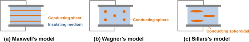
MWS polarization arises from the buildup of charges at phase or grain boundaries. The original polarization model was made by Maxwell for conducting sheets in an insulating medium. With some modifications by Wagner and Sillars, it can cover various conductor shapes [54]. (See Fig. 8. for clear classification of the models.) Recently, it has also been used for the heating mechanism of carbon-based solids by microwave [55,56], but without careful evaluations.
There are still some reservations about using MWS polarization as a mechanism for microwave heating of carbon-based solid materials. Originally, MWS polarization was derived for a perfect insulating medium containing a small quantity of conductors, so the dielectric loss factor (ε′′) of the continuous medium is ignored, because it is assumed to be perfectly insulating. In addition, the dielectric property (ε) of the whole is assumed to be the same as that of an insulating medium because the presence of the insulating medium is dominant. However, perfect insulators are rarely found in carbon-based materials. Furthermore, most carbon materials, like CNTs, graphite, carbon fiber and activated carbon, have a high proportion of conductive components. So there is a considerable discrepancy between carbonbased materials and the MWS polarization model.
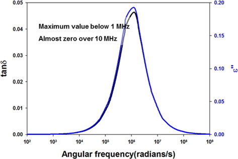
Another aspect to consider is frequency dependence. MWS polarization is dependent on frequency, like all other polarizations, so it is necessary to examine whether the theory is applicable in the microwave frequency range. As shown in Fig. 9, the parameters related to microwave heating (dielectric loss factor and loss tangent) have their peak values at much lower frequency (about 160 KHz) than common microwave frequencies (915 and 2450 MHz) when calculated using Wagner’s model [54]. There are a few reports which suggest MWS polarization happens in the low-frequency region [57], but no reports about the frequency dependence of MWS polarization with carbon-based materials.
It is true that MWS polarization occurs in electron-rich heterogeneous solids, but regarding MWS polarization as the main mechanism for microwave heating of carbon-based solids requires a logical leap. As mentioned above, the basic model of MWS polarization and the features of carbon-based solids are hugely different. Also, additional investigation is required to determine whether the polarization effect is large enough to be considered as a main mechanism for microwave heating of carbon- based solids or not. It is highly recommended to study the true mechanism of microwave heating for carbon-based solids both theoretically and experimentally.
Temperature control is essential for all chemical reactions. Both an extremely high heating rate and high temperature (above several hundred degrees Celsius) can be obtained in the microwave heating of carbon-based materials. An extreme heating rate can cause thermal shock, and excessive reaction temperature can cause undesired reactions.
Microwave heating is a result of the absorption of electromagnetic energy by materials. The average power absorbed by a material can be derived from Maxwell’s equation and expressed as below,
where
In the above equation, effective dielectric loss factor (
In reality, only a limited range of microwave frequencies are allowed to use for microwave heating, to avoid interference with microwave frequencies used for communication purposes. On the other hand, microwave power can be varied without restriction, though there are only a few papers investigating the effect of microwave power [19,42,43]. Most researchers have used commercial or domestic microwave ovens, which are made for cooking with a single or a limited power range [11,13,14,18,20,22,26,28,31,32,41,46-48,50]. Therefore, these researches are limited inasmuch as they reflect an observed reaction at just one fixed power level, which only gives a consistent heating rate and maximum temperature for a given target material.
Penetration depth has great importance in the microwave heating of conducting materials. The penetration depth of a field is defined as the distance from the surface to a certain internal point where the magnitude of field strength decreases to 1/e of the original magnitude at the surface [58]. The penetration depth of an electric field is expressed as below,
where
In the interior of a material beyond the penetration depth, microwave heating is poor because the field strength of the electromagnetic wave becomes weaker. Table 5 lists the penetration depth of various materials.
[Table 5.] Penetration depth of various materials at 915 MHz and 2.45 GHz [2]
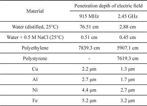
Penetration depth of various materials at 915 MHz and 2.45 GHz [2]
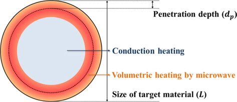
In general, microwaves heat a target material more homogeneously than a conventional method since the microwave has penetrative power, so volumetric heating is possible. However, it is not valid in all cases. When the scale of the target material is much larger than the microwave penetration depth, advantages like efficient and homogeneous heating are not applicable because the energy is only absorbed at the surface, as shown in Fig. 10.
Usually, liquids have a centimeter-scale penetration depth, so they can be effectively heated by microwaves by stirring or using a flow reactor. In the case of electron-rich solid systems like metals and carbons, however, penetration depth becomes a critical factor because the penetration depth is only micron-scale. Therefore, reactor design considering the penetration depth is strongly recommended when using microwaves as a heating source for carbon-based solids.
Microwave heating is a powerful heating method for carbonbased solid materials. In most cases, a temperature of over 1000℃ is obtained within a few minutes and is easily maintained, so processing time is absolutely shortened. Typical applications for microwave heating of carbon-based solid materials take advantage of the the ease of reaching and maintaining high temperature, and include the exfoliation of graphite, regeneration of carbon adsorbents, and reconstruction of crystalline structure. Furthermore, the selective-heating nature of microwaves is adequate for welding carbon-based materials with polymers.
In this review, various cases of microwave heating of carbonbased solid materials were introduced, including CNTs, graphite, activated carbons and carbon fibers. The diverse advantages of microwave heating are clearly shown experimentally, but deficient understanding about the heating mechanism and in the lack of a systematic approach are sticking points in advanced research.


![Frequency dependence of polarizations [2].](http://oak.go.kr/repository/journal/13498/HGTSB6_2014_v15n1_15_f002.jpg)
![Imaginary (ε’’) part of permittivity spectra of polymer composites with 0-23 wt% of single-wall carbon nanotube [5]. Reprinted with permission from [5]. Copyright ⓒ 2000, Elsevier.](http://oak.go.kr/repository/journal/13498/HGTSB6_2014_v15n1_15_f003.jpg)
![Transmission electron microscope images of vertically aligned carbon nanotubes after microwave treatment. (a) Fused nanotubes and (b) looped nanotubes after microwave irradiation [6]. Reprinted with permission from [6]. Copyright ⓒ 2003, American Chemical Society.](http://oak.go.kr/repository/journal/13498/HGTSB6_2014_v15n1_15_f004.jpg)
![Scanning electron microscope images of microwave welded single-wall carbon nanotube films (a) before and after microwave irradiation for (b) 7, (c) 9, or (d) 12 s at 40 W [15]. Reprinted with permission from [15]. Copyright ⓒ 2012, AIP Publishing LLC.](http://oak.go.kr/repository/journal/13498/HGTSB6_2014_v15n1_15_f005.jpg)


![Specific surface area and expansion volume of EGs prepared by microwave irradiation and pre-heated furnace [28]](http://oak.go.kr/repository/journal/13498/HGTSB6_2014_v15n1_15_t003.jpg)
![Scanning electron microscope images of exfoliated graphite by microwave exfoliation method [20]. Reprinted with permission from [20]. Copyright ⓒ 2010, Elsevier.](http://oak.go.kr/repository/journal/13498/HGTSB6_2014_v15n1_15_f006.jpg)
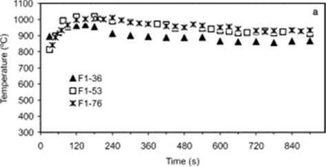
![Temperature profiles depending on the irradiation time during microwave treatment for activated carbon fibers [49]. Reprinted with permission from [49]. Copyright ⓒ 2001, Elsevier.](http://oak.go.kr/repository/journal/13498/HGTSB6_2014_v15n1_15_f007.jpg)

![Penetration depth of various materials at 915 MHz and 2.45 GHz [2]](http://oak.go.kr/repository/journal/13498/HGTSB6_2014_v15n1_15_t005.jpg)