The Hemispherical Resonator Gyroscope (HRG) is one of the vibratory gyroscopes that can be operated as an angle sensor or angular rate sensor, based on its operation mode. The vibratory gyroscope has the advantage of having no mechanically moving part, which means that it has less chance of operation failure, compared to the classical mechanical gyro. The working principle of the vibratory gyro is based on the Coriolis effect. If the external rotation of the platform occurs while the vibratory gyroscope is at the specific resonance mode termed ‘n=2 mode’, this external rotation causes precession of the resonance pattern angle. When the gyroscope is operated in angular rate measurement mode, the resonance pattern angle is controlled to have fixed value. By measuring the amount of pattern angle control input, the corresponding external angular rate can be estimated. The second mode is angle measurement mode. In this mode, the resonating pattern angle is allowed to precess freely, with respect to the external rotation. The external rotation angle can be estimated, by measuring the precession of the pattern angle.
In angle measurement mode, the pattern angle rotation is also affected by manufacturing error of the resonator, as well as the external rotation input. Although there are several other reasons, such as the temperature effect, the main reason that causes degradation of the angle estimation performance is the imperfection of the resonator. The imperfection of the resonator can be modeled with two parameters: frequency mismatch, and asymmetric damping. Frequency mismatch means the difference of the resonating frequency on two main axes. Asymmetric damping denotes the difference of the damping coefficient on two main axes.
To operate the vibratory gyros in angle measurement mode, its resonance should first be performed and maintained. Then, the quadrature vibration should be suppressed, and phase-locked loop should be applied [1]. The next task is to compensate the drift effect of the pattern angle, due to the imperfection parameter of the resonator. These imperfection parameters should be estimated, and correctly compensated, for accurate angle measurement.
There have been several researches on the control of the hemispherical resonator gyroscope. Lynch [1] has derived a slow-varying dynamic equation, which has the advantage that it is rather intuitive and easy to control, compared to the conventional fast-varying dynamic equation. He also designed a controller based on the slowvarying dynamics for angular rate measurement mode, by applying classical PI control law. Zuravlev [2] analyzed the drift effect of the resonating pattern angle, due to the imperfection of the resonator. Zhbanov [3] proposed a balancing mechanism to reduce the mass imbalance of the resonator, which causes the frequency mismatch of the resonator. As can be seen from the previous researches, most of the research deals with identifying and analyzing the drift effect of the resonator. However, there have been few researches to estimate the imperfection parameter, and compensate the drift effect. For the case of the MEMS (Micro-Electro-Mechanical System) gyroscope, there are several researches for compensating the drift effect of the resonator. Park [4, 5] applied adaptive control, based on a fast-varying dynamic equation. He also suggested applying a persistent excitation force, as well as the control force, to maintain the resonance.
In this paper, an imperfection parameter observer and corresponding compensation controller are designed for the hemispherical resonator gyroscope in angle measurement mode. The dynamic equation of the hemispherical resonator gyros is introduced, and analyzed. The imperfection parameter observer and compensation controller are designed based on the dynamic model, and are introduced. The observer for imperfection parameters is designed with nonlinear reduced order, and defining estimation error dynamics. The controller has two parts: the basic PI control, and the feedback linearization part, for compensation of the pattern angle drift effect. Finally, numerical simulation, which combines the proposed observer and controller, is performed for verification.
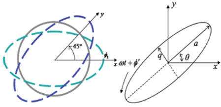
Before designing the observer of imperfection parameter and the controller for compensating the drift effect, a dynamic model of HRG should first be established. The dynamic model of HRG can be simplified, with its movement at the surface. The generalized CVG (Coriolis Vibratory Gyroscope) model is well known in this area [1]. A geometric representation is shown in Fig. 1.
The left side figure represents the shape of the resonator, seen from the tip. The x and y axes are 45 degrees separated, and the motions in each axis are independent of each other, for ideal gyros. The dynamic motions in the x and y axes are termed the generalized CVG model or fast-varying model, since the frequency of the dynamics is relatively high, compared to the slow-varying model. The right side figure denotes the slow-varying parameter, which is derived from the left side fast-varying dynamics. In the right side figure,
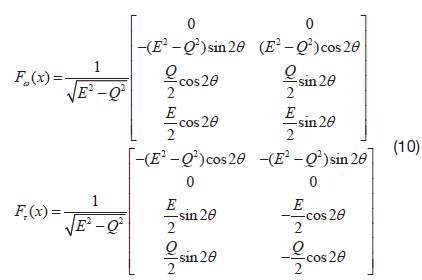
If no gravitational force and constant external rotation rate are assumed, the CVG model can be expressed as follows [1].
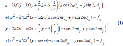
where,

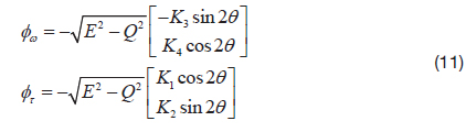
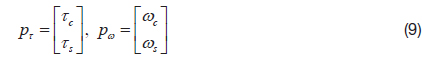
To design a nonlinear observer for the imperfection parameter, the dynamic model should be affine, with respect to the parameter to be estimated. The fast-varying equation of motion can be rewritten as below, using the affine imperfection parameters.
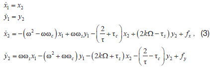
where, the imperfection parameters are given as below.

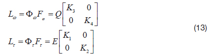
The fast-varying model is widely used to control the MEMS gyroscope. However, it has the disadvantage that the computational load is critical, since the control frequency should be higher than the resonance frequency. For this reason, the slow-varying model derived from the fast-varying model is widely used to control the HRG [1]. While the fast-varying model describes every instantaneous motion with respect to time, the slow-varying model describes the averaged motion of the resonating gyro, such as the resonating amplitude, the amount of quadrature vibration, and the resonating pattern angle. For this reason, the slowvarying model can reduce the computational load, and the parameter is rather intuitive, compared to the fast-varying model. The mathematical expression of the slow-varying model can be written as below [1].
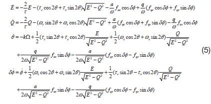
where,
This paper takes advantage of the slow-varying model to design the imperfection parameter observer and corresponding compensation controller.
Manufacturing of the HRG always produces imperfection, such as frequency split and asymmetric damping, as previously discussed. In this chapter, a nonlinear observer is designed, to estimate the imperfection parameter.
Using eq. (5), a nonlinear observer to estimate four unknowns is designed, based on Friedland’s approach [6].
The nonlinear reduced order observer has the following form.

where,
For the case that the dynamics is affine with respect to the unknown parameter, the dynamics can be rewritten as below.

where
with the estimation error definition that

If
In this paper, two separate observers are designed, as below.
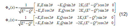
The corresponding Jacobian matrix for the dynamic equation can be written as below.

The nonlinear function □


where, K1, K2, K3, and K4 are constants that should be chosen appropriately for convergence.
Then, the matrix L(t) can be calculated, as follows.
For the conventional operation of HRG, the state variable E is controlled to have positive constant value for the amplitude control of the resonator, while the variable Q is controlled to be zero, for the suppression of quadrature vibration.
However, the two matrices

The overall purpose of the HRG control loop can be divided into four purposes: 1) keep its constant resonance (), 2) remove quadrature vibration (
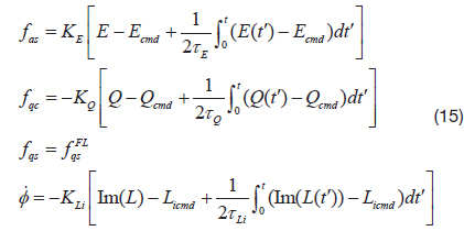
Lynch [1] proposed a PI controller for the angular rate sensing mode. In a similar way, a PI controller for the angle measurement mode can be designed, as below.

In eq. (15), fas is the control command to maintain the resonance amplitude, fqc is aimed to suppress the quadrature vibration, fqs is the resonating pattern angle control, and is the PLL (Phase-Locked Loop) command.
Since the angle measurement mode allows the pattern angle to precess freely with respect to the external rotation, the PI controller for pattern angle is not implemented. However, it is necessary to compensate drift effect on the pattern angle. The compensation control for pattern angle drift is proposed in the following section.
4.2 Drift Compensation Control
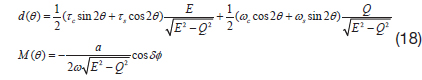
A feedback linearization method is used to cancel out the drift effect caused by imperfection of the resonator. To implement this approach, the imperfection parameter should be estimated properly, by using the parameter observer designed in the previous chapter.
The general expression for a dynamic model that includes an error parameter term can be written as below.

where,
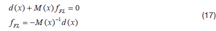
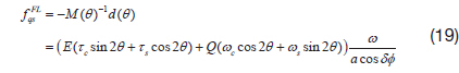
To cancel out the error term in the dynamic equation, feedback linearization control force can be implemented, as follows.

In eq. (5), all four state variables E, Q, θ,
Since the compensation control is implemented to the pattern angle only, it is computationally efficient.
As a result, the drift compensation controller is designed as below.
Numerical simulation is performed for verification of the proposed algorithm. The simulation parameters are defined as in Table 1.
[Table 1.] Simulation Condition
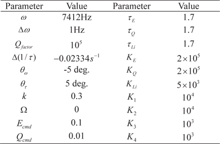
Simulation Condition
The first simulation is conducted for an imperfection parameter observer. Using the imperfection parameter estimated from the observer, the second simulation is aimed to compensate the drift effect.
5.1 Imperfection Parameter Observer
The imperfection parameter observer simulation is conducted for 120 seconds, with three stages. The first stage for 10 seconds is to control the slow-varying state only, with the basic PI controller discussed previously. This first stage is aimed to meet the persistent excitation condition, for the convergence of estimate error. The second stage for the next 40 seconds is to estimate the frequency mismatch parameter. The final stage is to estimate the asymmetric damping parameter, by using the estimated frequency mismatch parameter.
The simulation results are shown in Figs. 2, 3, and 4.
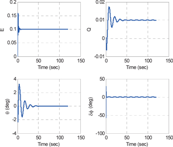
As seen from Fig. 2, the slow-varying state variables are controlled for persistent excitation, as discussed in eq. (14). Furthermore, the pattern angle is controlled to be zero, with the basic PI control proposed by Lynch [1].
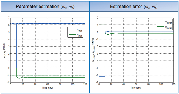
Fig. 3 shows estimation performance of the designed frequency mismatch observer. The frequency mismatch parameter observer shows satisfying performance. However, it has a slight steady-state error, since the observer uses the initial estimate value of the asymmetric damping parameter.
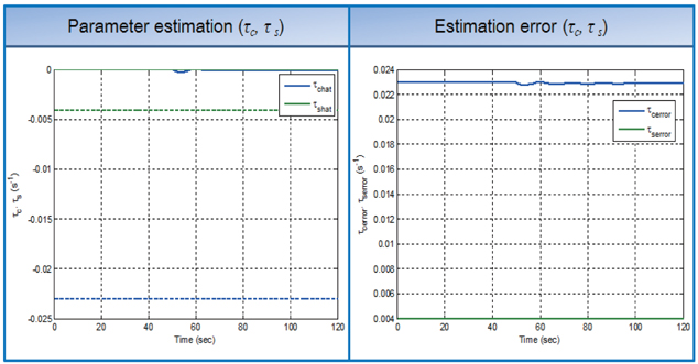
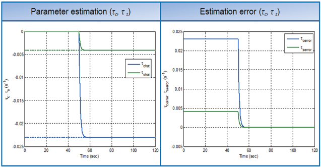
As seen from Fig. 4, the observer for asymmetric damping has poor estimation performance, compared to the frequency mismatch parameter observer. This error is caused by the estimation error of the frequency mismatch parameter.
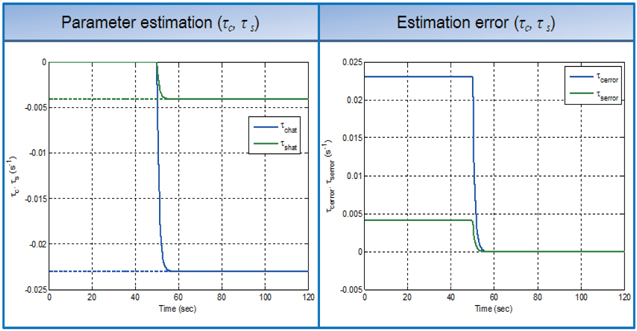
If there is no estimation error on the frequency mismatch parameter, the asymmetric damping observer converges exactly, as in Fig. 5.
To check the effect of persistent excitation control, the observer for frequency mismatch is simulated, when HRG is controlled as conventional operation mode (Qcmd=0). Fig. 6 shows that the observer diverges, since the persistent excitation condition is not met.
5.2 Drift Compensation Control
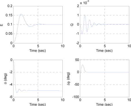
The drift compensation controller is also verified with numerical simulation. At first, numerical simulation for basic PI control without drift compensation control is performed, to analyze the drift effect. It is assumed that there is no external rotation. The result is shown in Fig. 7.
As seen from Fig. 7, the pattern angle rotates, even if there is no external rotation. Therefore, it is necessary to implement drift compensation control.
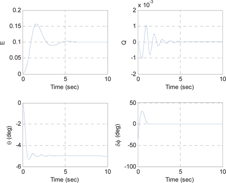
Fig. 8 shows the result when the drift compensation control is implemented with the estimated error parameter in section 5.1. The drift compensation control reduces the pattern angle drift effect, namely improving the performance of angle estimation. There still exists small drift error, caused by the small estimation error on each imperfection parameter.
A controller for the HRG in angle measurement mode is proposed. In this mode, the pattern angle drift effect caused by imperfection of the HRG significantly affects the angle estimation performance. For this reason, drift compensation control is necessary, for its accurate operation.
The controller is composed of basic PI control and drift compensation control, using a feedback linearization method.
To implement the drift compensation controller, estimation of the imperfection parameter is essential. This estimation is performed with the proposed nonlinear observer.
Furthermore, the persistent excitation condition is studied, for the convergence of the proposed observer.
Numerical simulation is performed with the proposed control algorithm and parameter observer, for verification. Although there is small estimation error for the imperfection parameter, the simulation results showed that the pattern angle drift effect due to the imperfection parameter is greatly reduced by the proposed imperfection parameter observer and drift compensation controller.