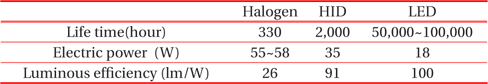
LED lighting is considered to be a growth industry and this can be regarded as an important factor for solving the environment and energy problems according to the global policy. It has higher illumination, longer life, and higher energy efficiency than other light sources such as halogen bulbs and high intensity discharge(HID) lamps, etc. Table 1 shows the characteristics of light sources, and an LED lamp has excellent life and light efficiency in comparison with a halogen lamp or an HID lamp. In addition, the LED lamp consumes about half of the HID lamp power.
[Table 1.] Characteristics of lights.

Characteristics of lights.
For automotive fog lamps, a 27 W-halogen lamp is generally used, and it is known that the power consumption can be reduced to as low as 10 W if using an LED lamp. While the life time is about 2,000 hours for halogen lamps, this can be extended to about 50,000 hours for LED lamps.
In summary, LED lamps have many advantages such as lower power consumption, longer life, higher color efficiency, no ultraviolet and infrared emission, and stronger durability against vibration and impact. However, LED lamps need to be thermally well managed to ensure their normal operation. In particular, high-power LED accelerates the decomposition between the parts due to phenomena such as the light efficiency reduction of the light beam, the reduction of the forward voltage, and the increase of the fundamental wavelength of the emitted light due to the heat occurring in the junction during operating; accordingly, the LED lifespan is reduced [1,2]. For LED lights, if the junction temperature reaches 135~150℃, the chip can become disconnected. Also, problems such as color-temperature variation and the reduction of the lifespan of LED can occur. A high-efficiency heat sink that can lower the temperature of the junction is therefore required [3].
Among LED heat sinks, the plate-fin heat sink [4,5] has typically been used because it does not require a high cost. Also, a heat pipe [6] is used for high-power LED lights due to its high heat transfer rate. In addition, many advanced cooling technologies that can greatly decrease high-power LED junction temperature are being studied. As shown in Fig. 1, the soldering method is used to remove the thermal resistance between the LED module and the aluminum body. The micro jet array cooling system has also been suggested [7,9], and similar cooling methods such as the use of a synthetic jet [10,11], a micro channel cooler [12], thermoelectric cooling [13], and a piezoelectric fan [14], etc. have been studied.
In order to increase the efficiency of LED lamps, Kim et al. [15] compared the performance of an LED lamp with and without heat pipes. In addition, Liu et al. [16] studied forced cooling technology using a micro jet, and reported that the junction temperature of LED could be further reduced by 23℃. Chen et al. [17] reported the effect of the contact resistance for LED with a metal core printed circuit board(MCPCB) through numerical analysis and experiment. Kang et al. [18] manufactured a heat sink for LED headlamps and studied the performances of cooling and illumination intensity by varying the fin-base area and fin length. Weng [19] numerically studied the relationship between thermal resistance and junction temperature under various conditions such as the material properties of the printed circuit board (PCB), the cooling condition, and chip size with a power of 0.1~1 W. He identified interactions between parameters and suggested a thermal design rule for the development of LED lights. Hwang, et al. [20,21] predicted the variation of junction temperature according to the fin shape, PCB material properties, and the number of LED modules for a 10 W LED light. They showed that the life time of a fan could be extended up to 164.5% by on-off control of the fan.
The lighting systems of some automobiles have already been replaced with LED lighting since it has high efficiency and long life. However, an LED lamp that can replace a halogen bulb of a used car has not yet been developed. Therefore, in this study, a high-efficiency and long-life LED fog lamp for a used-car market has been developed by optimizing thermal performance. First, to optimize the thermal performance of the LED fog lamp, the number of LED modules and the properties of the body, heat sink, and power were optimized. A prototype of a 10 W LED fog lamp was then manufactured and its thermal performance and illumination intensity were successfully verified from experiments.
2. NUMERICAL ANALYSIS AND EXPERIMENTAL METHOD
Thermal analysis was conducted to predict the junction temperature of an LED fog lamp. A steady-state thermal analysis module in Ansys [22] was adopted and, for the material properties and boundary conditions, the LED chip is assumed to be silicon, the lens is silicone, and the body and PCB are both aluminum.
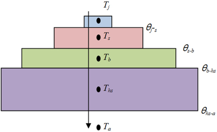
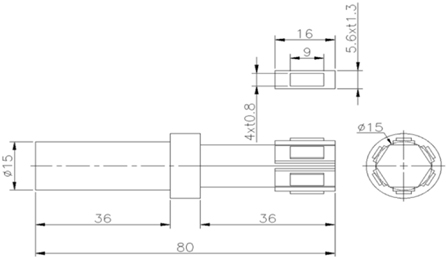
The heat conversion rate of LED power is about 70%. Furthermore, it is assumed that the outside air temperature was 25℃, the convective heat transfer coefficient is 2 W/m2K, the thermal resistance, and θj-s is 2℃ /W. An LED chip was modeled as a heat source for simplification of the grid and reduction of the analysis time in the numerical analysis. Figure 2 shows a schematic of the numerical model, and Fig. 3 shows the specification of the numerical analysis model.
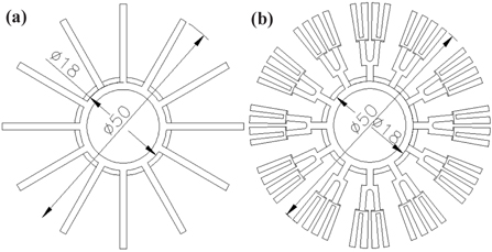
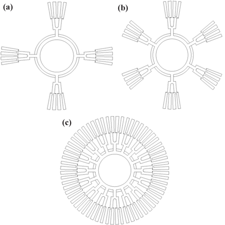
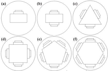
The number of LED modules plays an important role in decreasing the junction temperature due to the effect of power dispersion. Thus, in order to optimize the number of LED modules, the number of LED modules was increased from 1 to 6 as shown in Fig. 4. In addition, the LED thermal performance according to the shape of the heat sink was investigated, and the platefin heatsink and the radial-fin heatsink are shown in Fig. 5. The thermal performance was optimized by varying the fin number of the heatsink from 4 to16, as shown in Fig. 6. Table 2 shows a summary of the numerical analysis models considered in this study. Catia [23] was used for the three-dimensional shape design.
[Table 2.] Summary of numerical models with model number.
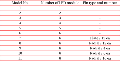
Summary of numerical models with model number.
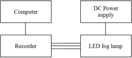
Figure 7 shows a schematic diagram of the heat radiation experiment. The thermal performance of an LED fog lamp was verified by applying power from 8 W to 12 W using a power supply. A T-type thermocouple was used to measure the temperature, and the data was obtained by using a recorder. The junction temperature (Tj) of the LED fog lamp was not directly measured but was calculated by using the solder point temperature (Tsp) and thermal resistance (θj-sp) given by the manufacturer. The relationship between Tj and Tsp is as follows:
When measuring the solder point temperature, the effect of radiation was minimized by wrapping the thermocouple with a radiation shield tape. The thermal equilibrium of the LED fog lamp was reached within 40 minutes after the LED light was turned on.
3.1 Junction temperature according to the number of LED modules
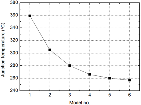
The case of LED modules mounted on the aluminum body without the heatsink was first considered. The junction temperature was numerically predicted by varying the number of LEDs, and the result is shown in Fig. 8. In the case of model 1,where a single LED module of high power is mounted, the junction temperature was as high as about 359℃. The target junction temperature should be below 100℃. When the number of modules increases with low-power chips, the junction temperature exponentially decreases, but the rate of decrease is gradually reduced. For model 6, where six LED modules are used, the junction temperature reaches about 257℃, showing a temperature decrease of 102℃ compared to model 1. Therefore, using multiple lowpower chips is more favorable for reducing junction temperature than using a single high-power LED due to the thermal dispersion effect. In general, phenomena such as chip disconnection, color temperature variation, and sudden life-shortening occur if the LED junction temperature reaches higher than 135~150℃. Thus, since the
Thermal management with the aluminum body alone is not sufficient, an additional thermal device such as a heat sink becomes necessary.
3.2 Junction temperature according to the fin shape of the heat sink
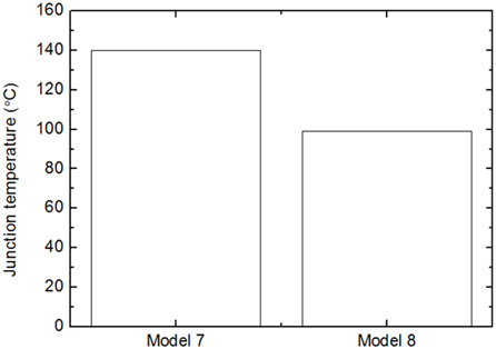
In this study, two types of heat sinks mounted on the aluminum body are considered to further improve the thermal performance of the LED light: the plate-fin type and the radial-fin type. Since the heat sink is assumed to be attached to the body by a soldering process, additional thermal contact resistance was not included. Figure 9 shows the variation of LED junction temperature with the shape of the heat sink. It was assumed that each heat sink has twelve fins. The junction temperature of model 7(the plate-fin type), is found to be about 140℃, and the junction temperature of model 8(the radial-fin type), is about 99℃. Thus, it can be seen that the radial-fin type is considerably more efficient in thermal management. This is mainly because the surface area of the radial-fin type is about 2.4 times larger than that of the plate-fin type. Although the junction temperature is below 100℃ for the radial-fin type, it can be further lowered by optimizing the number of radial fins.
3.3 Junction temperature according to the number of radial fins and amount of input power
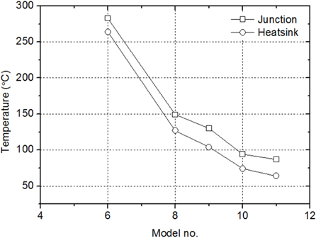
Figure 10 shows the variation of the LED junction temperature with the number of radial fins. The junction temperature of model 6 without a heat sink is 257℃. When the heat sink with four fins is mounted, the junction temperature lowers to about 149℃. This was expected since the surface area for heat release increases with the number of fins. The junction temperature of model 11 that has 16 fins decreased to about 87℃, and this corresponds to about a 42% decrease in the junction temperature compared to model 8. The ambient temperature of a car fog lamp can increase up to 45℃ in some places, such as in middleeastern countries. In this case, the junction temperature can increase from 87℃ to 107℃. However, it is still lower than 120℃, which is the maximum allowable junction temperature recommended by the manufacturer. Thus, if 6 LED modules and a heat sink with 16 radial fins are used, the thermal performance of a 10 W LED fog lamp can be sufficiently secured.
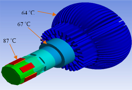
Figure 11 shows the contour plot of the surface temperature of model 11. While the LED junction temperature is 87℃, the temperatures of the body and heat sink are 67℃ and 64℃, respectively. Although there is a difference between the junction temperature and heat sink temperature, the tendency of temperature variation with the number of fins is similar.
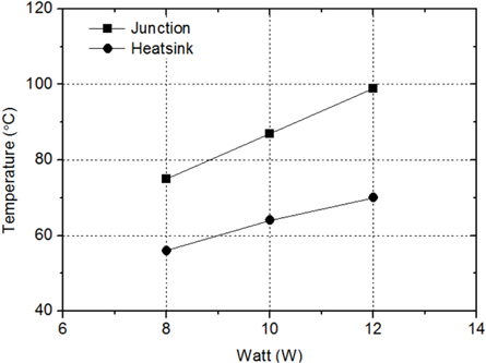
Currently, the power of commercial LED fog lamps ranges from 7.5 to 12 W. Thus, the variation of junction temperature with LED input power was studied. Figure 12 shows a variation of the junction temperature of model 11withinputpower. The junction temperature is linearly proportional to the input power. The junction temperature is 75℃ at 8 W of input power, whereas if the input power is increased to 12 W, the junction temperature increases to 99℃.For an ambient temperature of 45℃, the junction temperature becomes 119℃, which is still lower than the maximum allowable temperature of 120℃. This suggests that a 12 W LED fog lamp can be developed with 6 LED modules and 16 radial fins without any thermal problems.
3.4 Experiments on the thermal performance of an LED fog lamp prototype
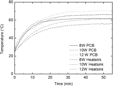
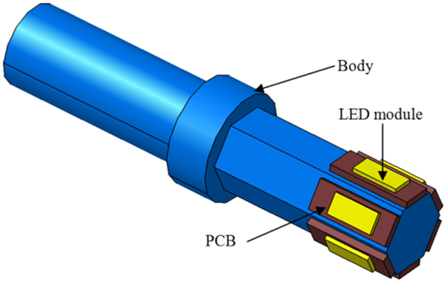
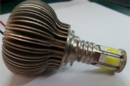
The prototype of the LED fog lamp was manufactured based on model 11, as shown in Fig. 13. Model 11 has an aluminum body with 6 LED modules and a heat sink with 16 radial fins. First, the variation of the junction temperature with input power was measured as shown in Fig. 14, where input power varies as 8 W, 10 W, and 12 W. The junction temperature was calculated from the measured temperature of the soldering point with the thermal resistance supplied by the manufacturer. At 8 W, the soldering point temperature was measured as 62.0℃, and the corresponding junction temperature was 78.0℃. As the input power gradually increases, the junction temperature also linearly increases with the power. At 10 W, the junction temperature reached 85.8℃ and increased to 94.6℃ at 12 W. Therefore, it is confirmed that the LED fog lamp developed in this study can be used with up to 12 W of input power. The illumination variation of the LED fog lamp with input power was also investigated. The intensity of illumination was measured at the distant point of 20 cm, perpendicular to the LED lens. The intensity of illumination was measured as 2,688, 3,181, and 3,610 lux for 8, 10, and 12 W, respectively. The typical illumination intensity of a 27 W halogen fog lamp is 1,010 lux, so the intensity of a 12 W LED lamp is 357% greater than that of a halogen lamp.
In this study, the properties of the LED module, the body, heat sink, and power of an LED fog lamp were optimized in order to develop an LED fog lamp that can replace halogen fog lamps in used cars. In addition, the performance of the fog lamp was verified with a prototype of the LED fog lamp. The conclusions drawn from this study are as follows:
(1) Multiple low-power LED’s are more advantageous in reducing the junction temperature of a fog lamp in comparison with a single high-power LED. The junction temperature with6 LED modules can be greatly reduced by 105℃ compared to a single LED module.(2) The radial-fin type heatsink is considerably more efficient than the plate-fin type for thermal management since it has 2.4 times more surface area for heat release. The radialfin type can lower the junction temperature by about 40℃ compared to the plate-fin type.(3) 6 LED modules, a heatsink with 16 radial fins, a 6-faces light body, and 12 W were finally determined as effective properties for LED fog lamps. The prototype of the LED fog lamp showed sufficient thermal performance, where the LED junction temperature is 94.6℃ for an input power of 12 Wand an ambient temperature of 25℃. In addition, the illumination intensity of the 12 W LED lamp was 357% greater than that of a typical halogen lamp.