Due to the increasing requirement for metrology accuracy, absolute testing of optics becomes a technological necessity. As an indispensable part of the absolute methods, the rotation technique can be divided into two basic categories: single-rotation algorithm [1-3] and rotation-averaging algorithm [4-6]. Based on least-squares fitting of Zernike polynomials, the single-rotation method requires only two measurements to work out the low-order surface deviation of the tested surface. The rotation-averaging algorithm measures the optics under test at N equally azimuthally spaced positions, and all of the rotationally asymmetric surface except that the Zernike terms whose angular order m equals kN can’t be calculated out. So we call this lost information
In this paper, a novel absolute testing algorithm with low error is proposed to measure the rotationally asymmetric surface deviation of optics. The theoretical formulas are derived; comparative analysis on the single-rotation algorithm and the new algorithm is presented.
For the single-rotation method, the original measurement result is expressed as:

where

Subtracting Eq. (1) from Eq. (2), the rotationally symmetric component of tested surface and the unvarying system errors cancel out and the following is hence obtained:

where

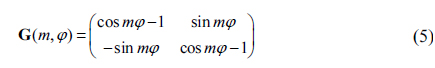
in which
However, as it’s intricate work to figure out the difference of variational errors, in the practical calculation, Δ

Subtract Eq. (6) from Eq. (4), the coefficient errors then are worked out:

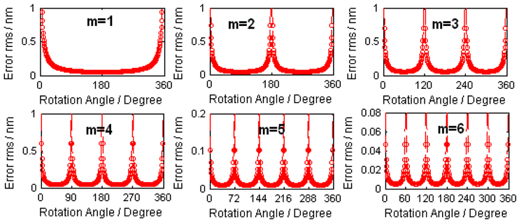
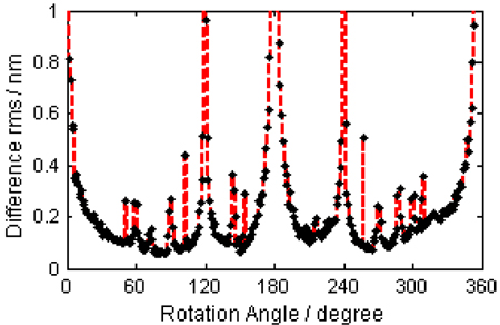
Then the error-sensitivity function is derived from Eq. (7):
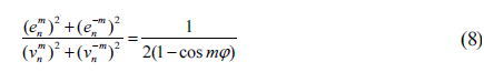
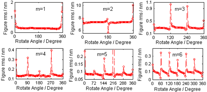
According to Eq. (8), when cos
[TABLE 1.] The pathological and optimal angles of each angular order
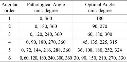
The pathological and optimal angles of each angular order
Founded on above analysis, our new algorithm decomposes the tested surface in terms of the angular order
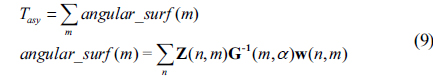
where Z(
It should be noted that some optimal angles are shared with more than one angular order. For example, the measurement result of 180° is available to all the odd angular surfaces. Therefore, the number of measurements is less than the maximum angular order of the surface of interest under test. For example, if a 64-term Zernike surface is required and the maximum angular order is 7, we just need 3 rotation angles: 180° for
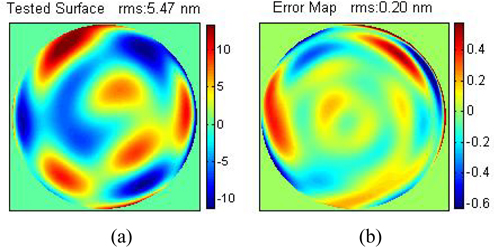
In the simulation, the surface deviation under test is composed by 64 Zernike terms (with fringe Zernike order, the same below), which is shown in Fig. 1(a). The difference error Δ
With 0.5° angle error and 0.5-pixel decentration error, the angular surfaces of
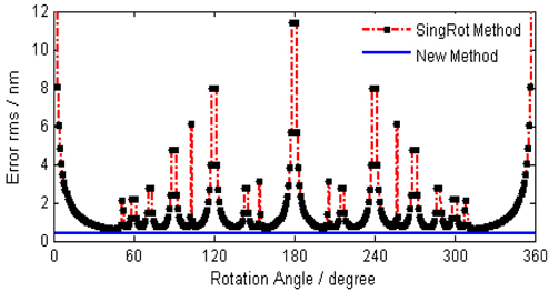
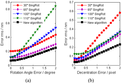
Simulation experiments are undertaken to gain more insight into the superiority of the new algorithm. A series of rotation angles aside from those pathological angles are applied to the single-rotation algorithm; three optimal angles (90,180,135 degree) are used in the new algorithm. Figure 4 shows the error
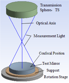
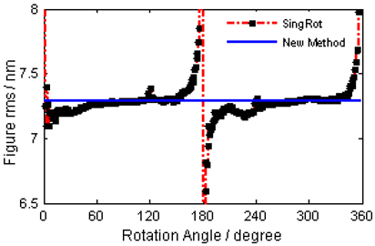
In the experimental verification of the new algorithm, a commercial Zygo-Fizeau interferometer is utilized to measure a spherical mirror with a clear aperture of 170 mm. Figure 5 depicts the sketch of the measurement instrument. The mirror is tested at 360 equally spaced angular positions rotating about the optical axis. The angular surfaces of
4.1. Comparison with the Single-rotation Algorithm
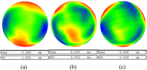
The low-frequency information (64 Zernike terms) of the surface under test is calculated by the new and the single-rotation algorithms separately. Figure 7 depicts the
Regard the result of the new algorithm as a criterion and subtract it from the surfaces solved by the singlerotation algorithm. Figure 8 shows the distribution of difference
4.2. Comparison with the Rotation-averaging Algorithm
Since the rotation-averaging algorithm can average random errors, it generally has a quite high accuracy. In order not to lose necessary information, an 8 rotation-averaging algorithm is applied to calculate the surface (64 Zernike terms). Subtract the solved surface from the other three results worked out above. The difference surface maps are shown in Fig. 9. The difference
Under a highly stable testing environment, the precision of the single-rotation method with an appropriate rotation angle can attain several nanometers; the precision of the rotation-averaging method can attain sub-nanometer if the lost surface information is ignored; as to the new algorithm, it also can achieve sub-nanometer due to its immunity to systematic errors. Certainly, this precision statement applies to those spherical mirrors with minor aperture (<500 mm) and lower deformation. In traditional testing, the dominating systematic error is the reference surface with 3~5 nm
We have proposed a novel absolute algorithm for the interferometric testing of rotationally asymmetric surface deviation of spherical optics. Based on least-square fitting of Zernike polynomials, it makes combinations of multiple evaluations of angular components of a surface into a final calibration data. The simulation and experiment results have been presented and coincide with each other. Compared with the single-rotation algorithm, the proposed algorithm requires more than one rotation measurement, nonetheless it can improve detection accuracy effectively; compared with the rotation-averaging algorithm, this algorithm can attain a comparable accuracy by fewer measurements. Therefore, the novel algorithm can achieve a balance between the efficiency and accuracy of measurement, and is more immune to the errors during testing.