검색 전체 메뉴
PDF
맨 위로
OA 학술지
Three-Dimensional Imaging and Display through Integral Photography
  • 비영리 CC BY-NC
  • 비영리 CC BY-NC
ABSTRACT
Three-Dimensional Imaging and Display through Integral Photography
KEYWORD
Computational photography , Integral imaging , Plenoptic imaging , Three-dimensional display
  • I. INTRODUCTION

    Nowadays, there is a trend of migrating from two-dimensional (2D) display systems to 3D ones. This migration, however, is not happening due to the fact that commercially available 3D display technologies are not able to stimulate all the mechanisms involved in the real observation of 3D scenes. The human visual system needs a set of physical and psychophysical clues to perceive the world as 3D. Among the psychophysical clues, we can list the linear perspective rule (two parallel lines converge at a far point), occlusions (occluded objects are further away than occluding ones), movement parallax (when the observer is moving, close objects displace faster than far objects), shadows, and textures.

    Among the physical clues are accommodation (capacity of eye lens to tune its optical power), convergence (rotation of the visual axes to converge at the object point), and binocular disparity (horizontal shift between retinal images of the same object). It is remarkable that the closer the object is to the observer, the stronger are the accommodation, convergence, and binocular disparity. The brain makes use of these physical clues to obtain information about the depth position of different parts of a 3D scene.

    Note that while psychophysical clues can be easily simulated in a 2D display, physical clues are difficult to simulate and indeed are not generated in currently commercially available 3D displays.

    The aim of this review is to analyze a 3D imaging and display architecture that at present is still far from the stage of commercial implementation but has the potential of successfully simulating all physiological and physical 3D clues.

    II. STEREOSCOPIC AND AUTOSTEREOSCOPIC TECHNIQUES

    At present, there are many techniques for the display of 3D images. Usually, the term 3D display is used for referring to two different visualization situations: the stereoscopic display and the real 3D display. Stereoscopic systems provide the user with two different images of the 3D scene, obtained from different but close perspectives. The images are shown independently to the eyes of the observer so that they produce binocular disparity, which provides the brain with the information that allows it to estimate the depth contents of the scene. Stereoscopy has been conventionally implemented by the use of special glasses that transmit for each eye its corresponding image and block the other one. This effect has been produced by the use of anaglyph glasses [1], polarizing glasses [2], and more recently, shutter glasses based on polarization [3, 4]. It is also possible to implement stereoscopy without the use of special glasses. The systems that perform this are known as auto-stereoscopic systems. Autostereoscopy can be imple- mented by means of lenticular sheets [5] or by parallax barriers [6, 7]. However, the main drawback of stereoscopy is that it produces ocular fatigue due to the conflict between convergence and accommodation. This conflict occurs due to the fact that the accommodation is fixed at the screen where the two perspectives are projected, whereas the visual axes intersect at the distance where the scene is recon- structed.

    The main difference between the stereoscopic and the real 3D displays is that the latter present different perspectives when the observer displaces parallel to the display. Among the real 3D displays, we can find multi-view systems based on lenticular sheets or on parallax barriers [8-10], volumetric systems [11], holographic systems [12], and integral photography systems [13-15]. From a conceptual point of view, holography, which can render the wave field reflected by an object, is the technique that provides a better 3D experience and does not produce visual fatigue. However, since holography is based on the interference of coherent wavefronts, it is still far from been efficiently applicable to massive 3D display media.

    Multi-view systems either based on parallax barriers or in lenticular sheets, provide the observer with multiple stereoscopic views of a 3D scene. These systems can provide different stereoscopic views to different observers, but have the drawback of flipping or double image, when the observer displaces parallel to the system. Multi-view systems do not provide images with vertical parallax, and more importantly, the users still suffer from the consequences of the convergence accommodation conflict.

    Integral imaging is, together with holography, the only technique that can stimulate both the physical and the psychophysical mechanisms of 3D vision. Integral imaging systems reconstruct any point of the 3D scene through the intersection of many rays, providing the observer with fullparallax images and avoiding the conflict between the mechanisms of convergence and accommodation [16, 17]. The main advantage of integral imaging nowadays is that it can be implemented with the available 2D imaging and display technology, such as charge-coupled device (CCD) or CMOS sensors and LED or LCD displays. In any case, there are still some physical limitations, such as the poor viewing angle, or technological limitations, such as the need for a higher resolution of pixelated monitors and a wider bandwidth for the transmission of integral images, that still prevent this technique from a rapid commercial spread. However, note that it is reasonably expected that these limitations will be overcome in the next few years.

    III. INTEGRAL IMAGING

    On March 2, 1908, Lippmann presented to the French Academy of Sciences his work ‘Epreuves réversibles photographies integrals’ [13], which postulated the possibility of capturing 3D information of an object on a photographic film. He proposed the use of a transparent sheet of celluloid to record on one surface a large number of small notches with circular relief intended to serve as lenses. On the other side of the sheet, he proposed to mold a series of diopters but coated with a photographic emulsion. Each of these spherical diopters should be adapted to receive the image provided by each of the lenses of the opposite face (see Fig. 1). Henceforth, we will refer to each of these images as elemental images.

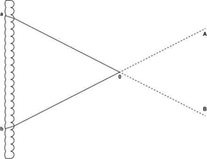
    During the capturing process, each lens forms the image of a slightly different perspective of the 3D scene on the photographic emulsion. In the display process, the positive of the developed image is pasted on the face where the photographic emulsion is applied and illuminated through a diffuser. Then, any point on the positive can generate a beam of parallel rays. As a result, a 3D scene is reconstructed by the intersection of these beams and can be observed within a range of angles (see Fig. 2).

    Despite the simplicity of Lippmann’s concept, its experimental implementation faced numerous technical difficulties. Experimental tests performed with a thermally molded film produced poor results. In 1912, Lippmann [15] conducted a new experiment with 12 sticks of glass mounted in a rectangular matrix. In this experiment, he proved the existence of a 3D image that can be seen from different perspectives and whose angular size can be changed to zoom in or out.

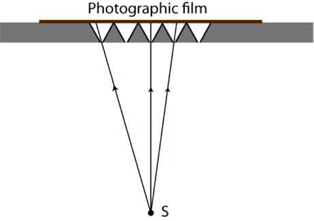
    Unfortunately, the technology for creating an array of small lenses was complex, and therefore, instead of using microlens arrays (MLAs), the experiments and investigations conducted during that time and in the following few years used pinhole arrays. However, pinholes have an important problem, in order to have sharp images, they need to have a small aperture, and thus, the light that goes through them is not sufficient to achieve an acceptable exposure time. In 1911, Sokolov [18] described and validated experimentally the integral photography method proposed by Lippmann. He built a pinhole array by piercing equidistant little cone-shaped holes in a sheet surface and applied a photographic emulsion (Fig. 3).

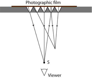
    In the reconstruction process (see Fig. 4), the recorded image replaced the photographic film. Another drawback of the pinhole array arises during reconstruction: instead of a continuous image, the viewer sees a series of discrete points [19].

    One of the main problems of integral imaging is pseudoscopy: the projected images are reversed in depth. Sokolov [18] showed this problem in one of his figures, which is similar to Fig. 4. The viewer sees point S closer to him than the other point if he is in front of the pinhole array, but if the viewer sees the 3D scene from the pinhole plane, he perceives point S to be farther than the other point. In 1931, Ives [20] analyzed this pseudoscopy problem in multi- perspective systems and proposed to capture, with an integral imaging system, the reconstructed image captured by another integral imaging system. This produces a double depth inversion that solves the problem.

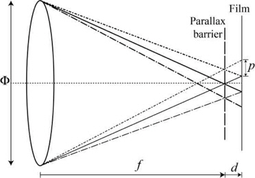
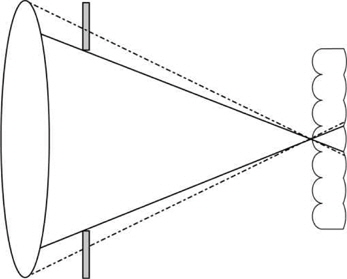
    In addition, Ives [21] was the first to propose the use of a field lens of a large diameter to form the image of an object through a parallax-barrier plate in order to obtain multi- perspective images (see Fig. 5). Later, in 1936, Coffey [22] proposed to combine the systems developed by Ives and Lippmann. He used a molded sheet with photographic emulsion, similar to the one designed by Lippmann. To avoid an overlap between the elemental images, Coffey [22] proposed the adjustment of the effective apertures of the field lens and the microlenses (see Fig. 6).

    The first commercial integral imaging camera was patented by Gruetzner [23] in 1955 In the patent, he reported a new method for recording a spherical lens pattern in a photographic film that was covered on one side by a light-sensitive emulsion.

    Between the late 1960s and the 1980s, interest in integral imaging increased. During this period, various theoretical analyses and experimental systems were implemented. The most notable researchers of this time were De Montebello [24-27], Burckhardt [28-30], Dudley [31, 32], Okoshi [33-35], and Dudnikov [36-41]. ‘MDH Products’, Montebello’s company, was the first to commercialize integral photographs for the general public. The first virtual integral images were produced by Chutjian and Collier [42] in 1968 while they worked for Bells Laboratory. These virtual images were obtained by calculating an integral image of computer-generated objects. The objects were calculated with inverted relief in order to produce a double depth inversion to obtain orthoscopic images.

    From 1988 to the last decade, the Davis and McCormick [43-50] group had been the most active in the integral imaging area; they published numerous studies and filed a number of patents. In 1991, Adelson and Bergen [51] introduced the concept of plenoptic function, which describes the radiance of each luminous light ray in space as a function of angle, wavelength, time, and position. This function contains any parameter that is susceptible to being captured by an optic device, and it is closely related with what Gibson [52] called ‘the ambient light structure’.

    The plenoptic function is a 5D function that in an environment free of occlusions and light absorption can be reduced to a 4D function. The first plenoptic camera was proposed in 1992 by Adelson and Wang [53]. In fact, they used the design proposed by Coffey [22] but added their plenoptic function for the formulation.

    Because of the possibility of capturing and reproducing integral images using digital media, the computer graphics community became interested in the concept of integral imaging. In 1996, Levoy and Hanrahan [54] renamed the 4D plenoptic function as ‘Light Field’ and Gortler et al. [55] used the term ‘The Lumigraph’ to describe the same function. In both cases, the researchers proposed the use of just one digital camera moved to different positions for capturing different perspectives of the object.

    In 1997, Okano et al. [56] captured, for the first time, integral images in real-time video frequency. Instead of using the habitual configuration, they used a high-resolution television camera to capture the different images formed behind an MLA. In 2002, Javidi and Okano [57] included transmission and real-time visualization. In particular, they proposed the use of a multicamera system organized in a matrix form for the capture, and an MLA placed in front of a high-resolution screen for the visualization.

    The information recorded with an integral imaging system has more uses than just optics reconstruction of 3D scenes, and it is possible to achieve computational reconstruction with different applications. One such application was proposed by Levoy and Hanrahan [54] and Gortler et al. [55]. They synthetized new views of a 3D scene from a discrete set of digital pictures captured from different perspectives. These views can be orthographic or with perspective. By using the different perspectives captured with an integral imaging system, we can simulate an image captured by a camera with the main lens with a superior diameter than the microlenses or cameras that sampled the plenoptic function. The depth of field of these images is smaller than that of each of the elemental images. It is also possible to obtain images of the scene focused to different depths, in planes perpendicular to the optics axis of the synthetic aperture [58] or in planes with arbitrary inclinations with respect to this axis [59].

    In 2005, the first portable plenoptic camera was built by Ng et al. [60], on the basis of that proposed by Adelson and Wang [53]. The key feature of this camera was to refocus computationally the photographs captured with a digital camera after they were taken. In order to overcome the low resolution of this system, Lumsdaine and Georgiev [61] implemented a new design named ‘Focused Plenoptic Camera’. They proposed to place the MLA in front of, or behind, the image plane. In such a case, the spatial resolution is increased at the expense of the angular resolution. Anyways, independently of the configuration used, a higher number of microlenses and a higher number of pixels behind each microlens will produce a higher spatial and angular resolution.

    Miniaturization and integration of chips in the MLA and in the light sensor is the future of integral imaging. In 2008, Fife et al. [62] designed the first integrated plenoptic sensor. Instead of taking the usual approach of using a sensor and a microlenses array, they designed and built a 166 × 76 sensor with small groups of 16 × 16 pixels. Over any of these groups and separated by a dielectric film, a small lens was placed for focalizing the light onto the group of pixels placed behind it.

    The interest in and the number of publications on the topic of integral imaging have increased exponentially during the last decade. The two main research topics have been to overcome the physical limitations and to search for new applications of integral imaging systems. For solving the physical limitations, several researchers have proposed solutions to the pseudoscopic problem [63-66], to the uncertainty in the position and angle of the microlenses and the elemental images with respect to the sensor [67-70], and to the limitation of the viewing angle [71-74]. Solutions to the limited depth of field [75-77] or to the detrimental effect of the facet braiding have also been proposed [78, 79].

    On the other hand, new applications of integral imaging have arisen. Some examples of these are the visualization of 3D content and TV systems based on integral imaging [80-82], and the automatic recognition of 3D objects [83-86]. Other interesting applications are the 3D image and processing systems of poorly illuminated 3D scenes based on multi-perspective photon counting [87-91], the 3D imaging and pattern recognition of scenes that present partial occlusions or immersed in dispersive environments [92, 93], and the 3D microscopy after a single shot [94-99].

    IV. CONCLUSIONS

    We have reported a review of the advances in the integral imaging technique. We have gone over more than one century of history of 3D imaging and found that this technique constitutes the most promising approach to the problem of showing 3D images in color to massive audiences. Besides, we have shown that this technique has many technological applications other than the 3D display.

참고문헌
  • 1. Rollmann W. 1853 “Notiz zur stereoskopie,” [Annalen der Physik] Vol.165 P.350-351 google cross ref
  • 2. Land E. H. 1937 “Polarizing optical system,” google
  • 3. Byatt D. W. 1981 “Stereoscopic television system,” google
  • 4. Bos P. J., Koehler/Beran K. R. 1984 “The pi-cell: a fast liquidcrystal optical-switching device,” [Molecular Crystals and Liquid Crystals] Vol.113 P.329-339 google cross ref
  • 5. Hess W. 1915 “Stereoscopic picture,” google
  • 6. Berthier A. 1896 “Images stereoscopiques de grand format,” [Le Cosmos] P.205-210 google
  • 7. Ives F. E. 1902 “A novel stereogram,” [Journal of the Franklin Institute] Vol.153 P.51-52 google cross ref
  • 8. Julesz B. 1963 “Stereopsis and binocular rivalry of contours,” [Journal of the Optical Society of America] Vol.53 P.994-998 google cross ref
  • 9. Kanolt C. W. 1918 “Photographic method and apparatus,” google
  • 10. Imai H., Imai M., Ogura Y., Kubota K. 1996 “Eye-position tracking stereoscopic display using image-shifting optics,” [Proceedings of SPIE] Vol.2653 P.49-55 google
  • 11. Blundell B. G., Schwarz A. J. 2000 Volumetric Three-Dimensional Display Systems google
  • 12. Gabor D. 1948 “A new microscopic principle,” [Nature] Vol.161 P.777-778 google cross ref
  • 13. Lippmann G. 1908 “Epreuves reversibles photographies integrals,” [Comptes Rendus de l'Academie des Sciences] Vol.146 P.446-451 google
  • 14. Lippmann G. 1908 “Epreuves reversibles donnant la sensation du relief,” [Journal de Physique Theorique et Appliquee] Vol.7 P.821-825 google cross ref
  • 15. Lippmann G. 1912 “L'etalon international de radium,” [Radium (Paris)] Vol.9 P.169-170 google cross ref
  • 16. Kim Y. 2012 “Accommodative response of integral imaging in near distance,,” [Journal of Display Technology] Vol.8 P.70-78 google cross ref
  • 17. Hiura H., Yano S., Mishina T., Arai J., Hisatomi K., Iwadate Y., Ito T. 2013 “A study on accommodation response and depth perception in viewing integral photography,” [in Proceedings of the 5th International Conference on 3D Systems and Applications (3DSA)] google
  • 18. Sokolov A. P. 1911 Autostereoscopy and integral photography by Professor Lippmann’s method google
  • 19. Martinez-Corral M., Martinez-Cuenca R., Saavedra G., Navarro H., Pons A., Javidi B. 2008 “Progresses in 3D integral imaging with optical processing,” [Journal of Physics: Conference Series] Vol.139 P.012012 google cross ref
  • 20. Ives H. E. 1931 “Optical properties of a Lippman lenticulated sheet,” [Journal of the Optical Society of America] Vol.21 P.171-176 google cross ref
  • 21. Ives H. E. 1930 “Parallax panoramagrams made with a large diameter lens,” [Journal of the Optical Society of America] Vol.20 P.332-340 google cross ref
  • 22. Coffey D. F. w. 1936 “Apparatus for making a composite stereograph,” google
  • 23. Gruetzner J. T. 1955 “Means for obtaining three-dimensional photography,” google
  • 24. De Montebello R. L. 1970 “Integral photography,” google
  • 25. De Montebello R. L. 1971 “Process of making reinforced lenticular sheet,” google
  • 26. De Montebello R. L. 1977 “Wide-angle integral photography: the integram system,” [Proceedings of the SPIE] Vol.120 P.73-91 google
  • 27. Buck H. S., de Montebello R. L., Globus R. P. 1988 “Integral photography apparatus and method of forming same,” google
  • 28. Burckhardt C. B., Collier R. J., Doherty E. T. 1968 “Formation and inversion of pseudoscopic images,” [Applied Optics] Vol.7 P.627-631 google cross ref
  • 29. Burckhardt C. B. 1968 “Optimum parameters and resolution limitation of integral photography,” [Journal of the Optical Society of America] Vol.58 P.71-74 google cross ref
  • 30. Burckhardt C. B., Doherty E. T. 1969 “Beaded plate recording of integral photographs,” [Applied Optics] Vol.8 P.2329-2331 google cross ref
  • 31. Dudley L. P. 1971 “Integral photography,” google
  • 32. Dudley L. P. 1972 “Methods of integral photography,” google
  • 33. Okoshi T. 1971 “Optimum design and depth resolution of lens-sheet and projection-type three-dimensional displays,” [Applied Optics] Vol.10 P.2284-2291 google cross ref
  • 34. Okoshi T., Yano A., Fukumori Y. 1971 “Curved triple-mirror screen for projection-type three-dimensional display,” [Applied Optics] Vol.10 P.482-489 google cross ref
  • 35. Okoshi T. 1976 Three-Dimensional Imaging Techniques google
  • 36. Dudnikov Y. A. 1970 “Autostereoscopy and integral photography,” [Optical Technology] Vol.37 P.422-426 google
  • 37. Dudnikov Y. A. 1971 “Elimination of pseudoscopy in integral photography,” [Optical Technology] Vol.38 P.140-143 google
  • 38. Dudnikov Yu. A. 1974 “Effect of three-dimensional moire in integral photography,” [Soviet Journal of Optical Technology] Vol.41 P.260-262 google
  • 39. Dudnikov Y. A., Rozhkov B. K. 1978 “Selecting the parameters of the lens-array photographing system in integral photography,” [Soviet Journal of Optical Technology] Vol.45 P.349-351 google
  • 40. Dudnikov Y. A., Rozhkov B. K. 1979 “Limiting capabilities of photographing various subjects by the integral photography method,” [Soviet Journal of Optical Technology] Vol.46 P.736-738 google
  • 41. Dudnikov Y. A., Rozhkov B. K., Antipova E. N. 1980 “Obtaining a portrait of a person by the integral photography method,” [Soviet Journal of Optical Technology] Vol.47 P.562-563 google
  • 42. Chutjian A., Collier R. J. 1968 “Recording and reconstructing three-dimensional images of computer-generated subjects by Lippmann integral photography,” [Applied Optics] Vol.7 P.99-103 google cross ref
  • 43. Yang L., McCormick M., Davies N. 1988 “Discussion of the optics of a new 3-D imaging system,” [Applied Optics] Vol.27 P.4529-4534 google cross ref
  • 44. Davies N., McCormick M., Yang L. 1988 “Three-dimensional imaging systems: a new development,” [Applied Optics] Vol.27 P.4520-4528 google cross ref
  • 45. Davies N., McCormick M. 1991 “Imaging system,” google
  • 46. Davies N. A., Brewin M., McCormick M. 1994 “Design and analysis of an image transfer system using microlens arrays,” [Optical Engineering] Vol.33 P.3624-3633 google cross ref
  • 47. Davies N., McCormick M. 1997 “Imaging system,” google
  • 48. Davies N., McCormick M. 1997 “Lens system with intermediate optical transmission microlens screen,” google
  • 49. Davies N., McCormick M. 1997 “Imaging arrangements,” google
  • 50. Davies N., McCormick M. 2000 “Imaging arrangements,” google
  • 51. Adelson E. H., Bergen J. R. 1991 “The plenoptic function and the elements of early vision,” [Computational Models of Visual Processing] Vol.1 P.3-20 google
  • 52. Gibson J. J. 1966 The Senses Considered as Perceptual Systems google
  • 53. Adelson E. H., Wang J. Y A. 1992 “Single lens stereo with a plenoptic camera,” [IEEE Transactions on Pattern Analysis and Machine Intelligence] Vol.14 P.99-106 google cross ref
  • 54. Levoy M., Hanrahan P. 1996 “Light field rendering,,” [in Proceedings of the 23rd Annual Conference on Computer Graphics and Interactive Techniques] P.31-42 google
  • 55. Gortler S. J., Grzeszczuk R., Szeliski R., Cohen M. F. 1996 “The lumigraph,,” [in Proceedings of the 23rd Annual Conference on Computer Graphics and Interactive Techniques] P.43-54 google
  • 56. Okano F., Hoshino H., Arai J., Yuyama I. 1997 “Real-time pickup method for a three-dimensional image based on integral photography,,” [Applied Optics] Vol.36 P.1598-1603 google cross ref
  • 57. Javidi B., Okano F. 2002 Three-Dimensional Television, Video, and Display Technologies google
  • 58. Isaksen A., McMillan L., Gortler S. J. 2000 “Dynamically reparameterized light fields,,” [in Proceedings of the 27th Annual Conference on Computer Graphics and Interactive Techniques] P.297-306 google
  • 59. Vaish V., Garg G., Talvala E. V., Antunez E., Wilburn B., Horowitz M., Levoy M. 2005 “Synthetic aperture focusing using a shear-warp factorization of the viewing transform,,” [in Proceedings of IEEE Computer Society Conference on Computer Vision and Pattern Recognition Workshop] P.129-129 google
  • 60. Ng R., . Levoy M., Bredif M., Duval G., Horowitz M., Hanrahan P. 2005 “Light field photography with a hand-held plenoptic camera,,” [Computer Science Technical Report] Vol.2 P.1-11 google
  • 61. Lumsdaine A., Georgiev T. 2009 “The focused plenoptic camera,,” [in Proceedings of IEEE International Conference on Computational Photography] P.1-8 google
  • 62. Fife K., El Gamal A., Wong H. S. P. 2008 “A multi-aperture image sensor with 0.7 μm pixels in 0.11 μm CMOS technology,” [IEEE Journal of Solid-State Circuits] Vol.43 P.2990-3005 google cross ref
  • 63. Arai J., Okano F., Hoshino H., Yuyama I. 1998 “Gradient-index lens-array method based on real-time integral photography for three-dimensional images,” [Applied Optics] Vol.37 P.2034-2045 google cross ref
  • 64. Min M. S., Hong J., Lee B. 2004 “Analysis of an optical depth converter used in a three-dimensional integral imaging system,” [Applied Optics] Vol.43 P.4539-4549 google cross ref
  • 65. Arai J., Kawai H., Kawakita M., Okano F. 2008 “Depth-control method for integral imaging,” [Optics Letters] Vol.33 P.279-281 google cross ref
  • 66. Navarro H., Martinez-Cuenca R., Saavedra G., Martinez-Corral M., Javidi B. 2010 “3D integral imaging display by smart pseudoscopic-to-orthoscopic conversion (SPOC),” [Optics Express] Vol.18 P.25573-25583 google cross ref
  • 67. Arai J., Okui M., Kobayashi M., Okano F. 2004 “Geometrical effects of positional errors in integral photography,” [Journal of the Optical Society of America A] Vol.21 P.951-958 google
  • 68. Tavakoli B., Daneshpanah M., Javidi B., Watson E. 2007 “Performance of 3D integral imaging with position uncertainty,” [Optics Express] Vol.15 P.11889-11902 google cross ref
  • 69. Aggoun A. 2006 “Pre-processing of integral images for 3-D displays,” [Journal of Display Technology] Vol.2 P.393-400 google cross ref
  • 70. Sgouros N. P., Athineos S. S., Sangriotis M. S., Papageorgas P. G., Theofanous N. G. 2006 “Accurate lattice extraction in integral images,” [Optics Express] Vol.14 P.10403-10409 google cross ref
  • 71. Jung S., Park J. H., Choi H., Lee B. 2003 “Viewing-angleenhanced integral three-dimensional imaging along all directions without mechanical movement,” [Optics Express] Vol.11 P.1346-1356 google cross ref
  • 72. Lee B., Jung S., Park J. H. 2002 “Viewing-angle-enhanced integral imaging by lens switching,” [Optics Letters] Vol.27 P.818-820 google cross ref
  • 73. Jang J. S., Javidi B. 2003 “Improvement of viewing angle in integral imaging by use of moving lenslet arrays with low fill factor,” [Applied Optics] Vol.42 P.1996-2002 google cross ref
  • 74. Martinez-Cuenca R., Navarro H., Saavedra G., Javidi B., Martinez-Corral M. 2007 “Enhanced viewing-angle integral imaging by multiple-axis telecentric relay system,” [Optics Express] Vol.15 P.16255-16260 google cross ref
  • 75. Martinez-Corral M., Javidi B., Martinez-Cuenca R., Saavedra G. 2004 “Integral imaging with improved depth of field by use of amplitude-modulated microlens arrays,” [Applied Optics] Vol.43 P.5806-5813 google cross ref
  • 76. Martinez-Cuenca R., Saavedra G., Martinez-Corral M., Javidi B. 2005 “Extended depth-of-field 3-D display and visualization by combination of amplitude-modulated microlenses and deconvolution tools,” [Journal of Display Technology] Vol.1 P.321-327 google cross ref
  • 77. Castro A., Frauel Y., Javidi B. 2007 “Integral imaging with large depth of field using an asymmetric phase mask,” [Optics Express] Vol.15 P.10266-10273 google cross ref
  • 78. Martinez-Cuenca R., Saavedra G., Pons A., Javidi B., Martinez-Corral M. 2007 “Facet braiding: a fundamental problem in integral imaging,” [Optics Letters] Vol.32 P.1078-1080 google cross ref
  • 79. Navarro H., Martinez-Cuenca R., Molina-Martin A., Martinez-Corral M., Saavedra G., Javidi B. 2010 “Method to remedy image degradations due to facet braiding in 3D integral-imaging monitors,” [Journal of Display Technology] Vol.6 P.404-411 google cross ref
  • 80. Okano F., Arai J., Mitani K., Okui M. 2006 “Real-time integral imaging based on extremely high resolution video system,” [Proceedings of the IEEE] Vol.94 P.490-501 google cross ref
  • 81. Mishina T. 2010 “3D television system based on integral photography,” [in Proceedings of the 28th Picture Coding Symposium] P.20-20 google
  • 82. Arai J., Okano F., Kawakita M., Okui M., Haino Y., Yoshimura M., Sato M. 2010 “Integral three-dimensional television using a 33-megapixel imaging system,” [Journal of Display Technology] Vol.6 P.422-430 google cross ref
  • 83. Matoba O., Tajahuerce E., Javidi B. 2001 “Real-time threedimensional object recognition with multiple perspectives imaging,” [Applied Optics] Vol.40 P.3318-3325 google cross ref
  • 84. Kishk S., Javidi B. 2003 “Improved resolution 3D object sensing and recognition using time multiplexed computational integral imaging,” [Optics Express] Vol.11 P.3528-3541 google cross ref
  • 85. Hong S. H., Javidi B. 2006 “Distortion-tolerant 3D recognition of occluded objects using computational integral imaging,” [Optics Express] Vol.14 P.12085-12095 google cross ref
  • 86. Schulein R., Do C. M., Javidi B. 2010 “Distortion-tolerant 3D recognition of underwater objects using neural networks,” [Journal of the Optical Society of America A] Vol.27 P.461-468 google cross ref
  • 87. Yeom S., Javidi B., Watson E. 2007 “Three-dimensional distortiontolerant object recognition using photon-counting integral imaging,” [Optics Express] Vol.15 P.1513-1533 google cross ref
  • 88. Tavakoli B., Javidi B., Watson E. 2008 “Three dimensional visualization by photon counting computational integral imaging,” [Optics Express] Vol.16 P.4426-4436 google cross ref
  • 89. DaneshPanah M., Javidi B., Watson E. 2010 “Three dimensional object recognition with photon counting imagery in the presence of noise,” [Optics Express] Vol.18 P.26450-26460 google cross ref
  • 90. Moon I., Javidi B. 2009 “Three-dimensional recognition of photonstarved events using computational integral imaging and statistical sampling,” [Optics Letters] Vol.34 P.731-733 google cross ref
  • 91. Aloni D., Stern A., Javidi B. 2011 “Three-dimensional photon counting integral imaging reconstruction using penalized maximum likelihood expectation maximization,” [Optics Express] Vol.19 P.19681-19687 google cross ref
  • 92. Hong S. H., Javidi B. 2005 “Three-dimensional visualization of partially occluded objects using integral imaging,” [Journal of Display Technology] Vol.1 P.354-359 google cross ref
  • 93. Moon I., Javidi B. 2008 “Three-dimensional visualization of objects in scattering medium by use of computational integral imaging,” [Optics Express] Vol.16 P.13080-13089 google cross ref
  • 94. Jang J. S., Javidi B. 2004 “Three-dimensional integral imaging of micro-objects,” [Optics Letters] Vol.29 P.1230-1232 google cross ref
  • 95. Levoy M., Ng R., Adams A., Footer M., Horowitz M. 2006 “Light field microscopy,” [ACM Transactions on Graphics] Vol.25 P.924-934 google cross ref
  • 96. Javidi B., Moon I., Yeom S. 2006 “Three-dimensional identification of biological microorganism using integral imaging,” [Optics Express] Vol.14 P.12096-12108 google cross ref
  • 97. Levoy M., Zhang Z., McDowall I. 2009 “Recording and controlling the 4D light field in a microscope using microlens arrays,” [Journal of Microscopy] Vol.235 P.144-162 google cross ref
  • 98. Shin D., Cho M., Javidi B. 2010 “Three-dimensional optical microscopy using axially distributed image sensing,” [Optics Letters] Vol.35 P.3646-3648 google cross ref
  • 99. Navarro H., Martinez-Corral M., Javidi B., Sanchez-Ortiga E., Doblas A., Saavedra G. 2011 “Axial segmentation of 3D images through syntetic-apodization integral-imaging microscopy,” [in Proceedings of Focus on Microscopy Conference] google
OAK XML 통계
이미지 / 테이블
  • [ Fig. 1. ]  Scheme of the molded sheet proposed by Lippmann.
    Scheme of the molded sheet proposed by Lippmann.
  • [ Fig. 2. ]  Reconstruction process as proposed by Lippmann.
    Reconstruction process as proposed by Lippmann.
  • [ Fig. 3. ]  Recording of light proceeding from a point source in a photographic film through a pinhole array with a conic shape.
    Recording of light proceeding from a point source in a photographic film through a pinhole array with a conic shape.
  • [ Fig. 4. ]  3D image reconstruction using a pinhole array.
    3D image reconstruction using a pinhole array.
  • [ Fig. 5. ]  Large-diameter lens projecting an image in the photographic plate through a parallax barrier.
    Large-diameter lens projecting an image in the photographic plate through a parallax barrier.
  • [ Fig. 6. ]  Procedure for adjusting the effective numerical aperture of the main lens with the numerical aperture of the microlenses.
    Procedure for adjusting the effective numerical aperture of the main lens with the numerical aperture of the microlenses.
(우)06579 서울시 서초구 반포대로 201(반포동)
Tel. 02-537-6389 | Fax. 02-590-0571 | 문의 : oak2014@korea.kr
Copyright(c) National Library of Korea. All rights reserved.