Dispersion management (DM) ensures the best performance of a high bit rate optical transmission system [1]. In addition, in long-haul transmission systems, the DM technique is an efficient way of compensating for optical signal distortion due to group velocity dispersion (GVD) because fiber losses can be efficiently managed by inline erbium-doped fiber amplifiers (EDFAs). In the conventional dispersion managed optical links, the nonzero anomalous GVD of single-mode fiber (SMF) is periodically compensated by the proper length of dispersion-compensating fiber (DCF) placed at the input or output end of the compensation interval [2].
DM includes careful tuning of the amount of GVD 1) directly after the transmitter (pre-compensation), 2) within the repeaters (in-line compensation), and 3) directly before the receiver (post-compensation) [3]. In in-line compensation, residual dispersion per span (RDPS) is defined as dispersion accumulated in each fiber span, and net residual dispersion (NRD) is defined as the total dispersion accumulated at the end of the transmission link. Generally, NRD is determined by controlling pre- or post-compensation and RDPS. Pre- and post-compensation, RDPS, and NRD are key parameters for improving system performance in DM techniques [3].
Besides GVD, nonlinear effects impose severe limitations on optical transmission systems, especially at high input power, mainly due to EDFAs. The dominant nonlinear effect is self-phase modulation (SPM), which is caused by the nonlinear dependence of the refractive index on the pulse intensity. Since high-speed data transmission systems require greater received power for error-free detection, the performance of a dispersion-managed link is eventually limited by the interaction of SPM and the fiber GVD [2, 4, 5]. Moreover, the mutual interplay between SPM and GVD depends on the sign and amount of residual dispersion [2].
Optical phase conjugation is another effective technique for reducing nonlinear impairment mainly due to SPM as well as GVD impairment [6-12]. The compensation for signal impairment in this technique is theoretically possible through the use of an optical phase conjugator (OPC) in the middle of the total transmission length. However, the effective suppression and mitigation of nonlinear impairment is not practically obtained in optical transmission systems using only OPC because nonlinearity cancellation requires a perfectly symmetrical distribution of power and local dispersion with respect to the OPC position. Due to the presence of fiber attenuation and amplification, this condition cannot be satisfied in real links [6].
However, there are a number of techniques to overcome this drawback. For example, optimizing the OPC position [9, 10] or combining appropriate dispersion mapping [11, 12], has been proposed recently. In order to suppress nonlinearity impairments to a large extent, the system parameters of an OPC link, such as the location of OPC or the dispersion map, need be optimized.
In the techniques mentioned above and other techniques concerned with in-line DM, the SMF length and RDPS of every fiber span are assumed to be uniform for simplicity of optical link configuration. However, the SMF length and RDPS need to be unlimited for flexible implementation of optical network topology. The adaptive configuration of the SMF length and RDPS is possible by arranging them in a random distribution. However, this method can result in a complex link configuration and it is difficult to obtain an optimal random pattern. However, it should be possible to set up a flexible link configuration by using artificial distributions of the SMF length and RDPS, such as ascending and descending distribution of each of them as the number of fiber spans increase. This distribution method is more advantageous for obtaining an optimal distribution pattern, since the number of cases to be investigated is smaller than with a random distribution. Therefore, this work numerically investigates the possibility of the flexible configuration of the optical links with OPC and DM by adopting an artificial distribution of the SMF length and RDPS. The artificial distribution patterns considered in this paper are generated by combinations of ascending distributions and descending distributions of each SMF length and RDPS. Generally, the extent of RDPS and the dispersion coefficient of DCF affect the system performance in DM links. Thus, three average RDPS values of half a transmission section, such as 0, 300, and 550 ps/nm, and two dispersion coefficients of DCF, such as -50 and -100 ps/nm/km are considered to assess the system performance.
II. WDM TRANSMISSION MODELING AND THE NUMERICAL ASSESSMENT METHOD
>
A. Modeling of WDM Transmission System
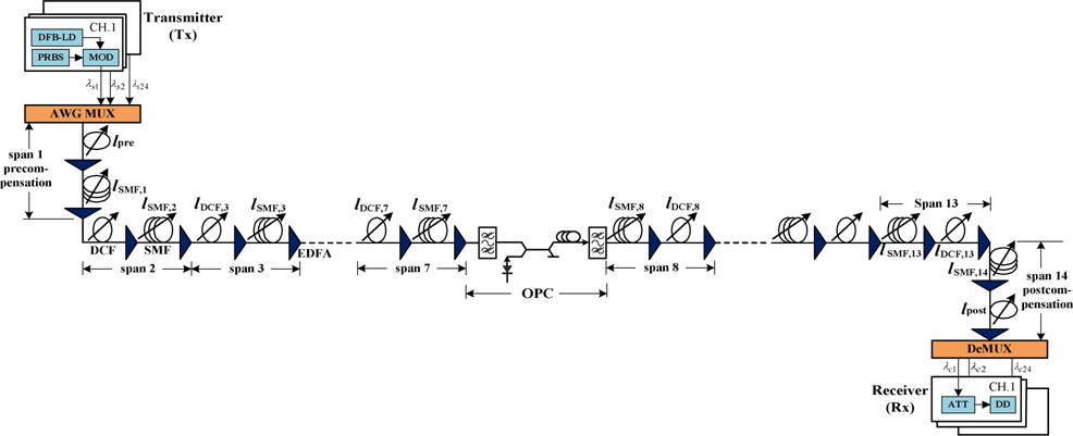
The configuration of the OPC is illustrated in the middle of the optical links shown in Fig. 1. The nonlinear medium of the OPC is assumed to be the highly nonlinear dispersion-shifted fiber (HNL-DSF). The parameters of the OPC are as follows: loss of HNL-DSF
The transmitter (Tx) for the 24-channel WDM shown in Fig. 1 is assumed to be a distributed feedback laser diode (DFB-LD). The center wavelengths of the DFB-LDs are assumed to be 1,550–1,568.4 nm by spacing 100 GHz (0.8 nm) based on ITU-T recommendation G.694.1. DFB-LDs are externally modulated by an independent 40 Gbps 127 (=27-1) pseudo-random bit sequence. The modulation formats from the external optical modulators are assumed to be return-to-zero (RZ), while the output electric field of the RZ format is assumed to be a second-order super-Gaussian pulse with a 10 dB extinction ratio, 0.5 duty cycle, and chirp-free. The optical signals propagating through the earlier half section (span 1 to 7) are converted to the conjugated signals with wavelengths of 1549.5–1528.5 nm by the midway OPC. The 3-dB bandwidth of the conversion efficiency is calculated to almost 48 nm (1526–1574 nm) from the previously mentioned OPC parameters. Thus, all of the signal wavelengths and these conjugated wavelengths belong within the 3-dB bandwidth of the conversion efficiency.
The receiver (Rx) consists of the pre-amplifier of the EDFA with a 5 dB noise figure, an optical filter of 1 nm bandwidth, PIN diode, pulse shaping filter (Butterworth filter), and the decision circuit. The receiver bandwidth is assumed to be 0.65 × bit-rate [13].
>
B. Modeling of Optical Links
The optical transmission link shown in Fig. 1 consists of 14 fiber spans, which include SMF and DCF. The SMF lengths of all of the spans and DCF lengths from the second span to the 13th span are varied for artificial distributions. However, the rest of the fiber parameters are fixed as follows: the attenuation coefficient of SMF
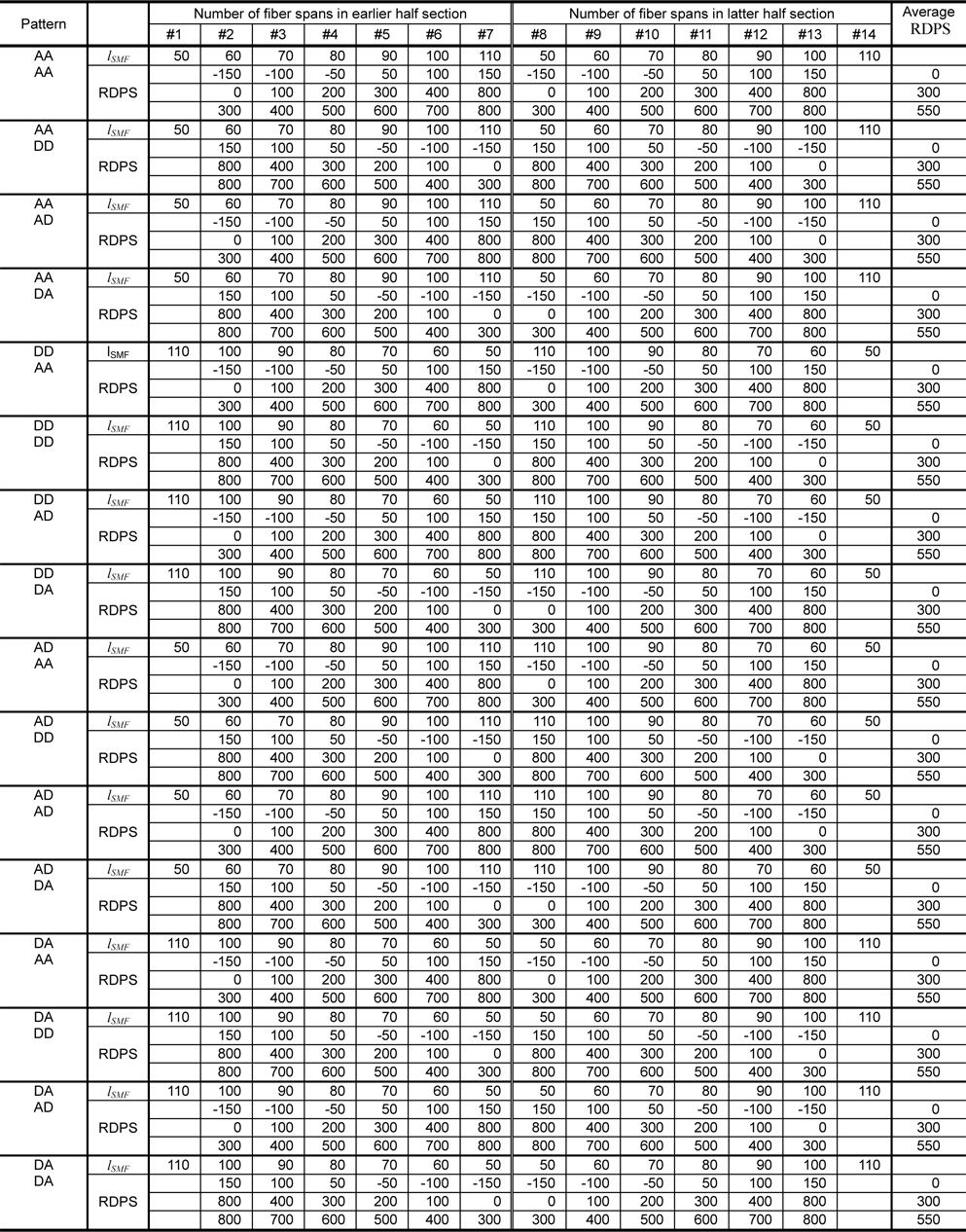
The SMF length distributions in both half sections are ascending from 50 to 110 km or descending from 110 to 50 km (10 km interval) for the artificial distribution as the number of the fiber span increases, as shown in Table 1. There are 4 combinations of artificial distribution patterns of both half sections: ascending distribution in the earlier half section + ascending distribution in latter half section (labeled “AA”), descending + descending (labeled “DD”), ascending + descending (labeled “AD”), and descending + ascending (labeled “DA”).
[Table 1.] Artificial distribution patterns of the SMF length and RDPS

Artificial distribution patterns of the SMF length and RDPS
The average RDPS is assumed to be equal to the value of 0, 300, and 550 ps/nm for both half sections, except the first fiber span and last fiber span. The exact RDPS distributions in both half sections are ascending or descending by using -150, -100, -50, 50, 100, and 150 ps/nm in case of a 0 ps/nm average RDPS; 0, 100, 200, 300, 400, and 800 ps/nm in case of a 300 ps/nm average RDPS; and 300, 400, 500, 600, 700, and 800 ps/nm in case of a 550 ps/nm average RDPS. There are also 4 combinations of artificial distribution patterns of the two half sections: AA, DD, AD and DA. The exact RDPS of each fiber span is then identified by determining the DCF length
Thus, there are 16 combinations of artificial distribution patterns of the SMF length and exact RDPS for the average RDPS, as summarized in Table 1. In Table 1, the notations in the left row mean the artificial distribution patterns of the SMF lengths and exact RDPS in the earlier half section and latter half section, respectively. For example, “AD + DA” means the optical link with ascending distribution of the SMF lengths in the earlier half section, descending distribution of SMF lengths in the latter half section, descending distribution of the exact RDPSs in the earlier half section and ascending distribution of the exact RDPSs in latter half section.
The DCF length of the first fiber span or the last fiber span, excluded from 14 fiber spans, that is, lpre or lpost, is used to determine the NRD of the optical link, as plotted in Fig. 1. When deciding on the NRD by only pre- compensation, the NRD depends on the variable length of the first DCF,
The optical links with the uniform distribution of the SMF length and RDPS are used to compare with the system performance obtained in the artificial distribution. The SMF length of every fiber span has to be 80 km for a uniform distribution, since the average value is 80 km for the artificial distribution. Furthermore, the DCF lengths from the second to 13th fiber spans have to be 13.6, 31.6, and 46.6 km in the optical links with 0, 300, and 550 ps/nm RDPS uniformly distributed, respectively, when using a - 100 ps/nm/km dispersion coefficient for the DCF. On the other hand, DCF lengths for 0, 300, and 550 ps/nm have to be 27.2, 63.2, and 93.2 km, respectively, when using a -50 ps/nm/km dispersion coefficient for the DCF.
>
C. Numerical Assessment Method
The propagation of a signal in a lossy, dispersive, and nonlinear medium can be expressed by the nonlinear Schrodinger equation assuming a slowly varying envelope approximation. The numerical approach of (1) is completed by using a split-step Fourier method [14].
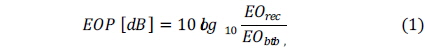
The eye opening penalty (EOP) is used to assess the system performance of the receiving WDM signals in this work, according to the following equation:
where
III. SIMULATION AND DISCUSSION
It had been previously confirmed that the optimal NRDs controlled by pre- and post-compensation were 10 and -10 ps/nm, respectively, regardless of the SMF length, RDPS, launch power, and dispersion coefficient [15, 16]. These results are remarkably consistent with the result of Xiao’s study dealing with “pseudolinear” systems [3]. We confirmed that the optimal NRDs of the optical links proposed in this paper are also the abovementioned values. Thus, assessment and the analysis of system performances will be carried out under the conditions of NRD = 10 and - 10 ps/nm by pre- and post-compensation, respectively.
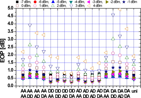
Fig. 2 shows the EOPs of the worst channel among 24 WDM channels depending on the launch power as a function of 16 combinations of artificial distribution patterns in the optical links of NRD = 10 ps/nm by pre-compensation, in which a 0 ps/nm average RDPS and -50 ps/nm/km dispersion coefficient of the DCF are used. Fig. 2 also shows the EOPs of the worst channel in the optical links with the uniform distribution as an 80 km SMF length and RDPS = 0 ps/nm (marked by ‘uni’ on the x-axis) as a performance comparison.
We confirmed that the EOP depends on the launch power and distribution pattern of the SMF lengths and RDPSs; however, the EOP characteristics of particular artificial distribution patterns are superior to the uniform distribution of the SMF length and RDPS. In Fig. 2, all the EOPs for the launch power considered, that is, from -7 to 4 dBm, in the optical link configuration arranged in the ‘DD + AD’ and ‘DD + DA’ combinations are lower than 1 dB. On the other hand, in the optical link with the uniform distribution, the EOPs exceed 1 dB for a 1–4 dBm launch power.
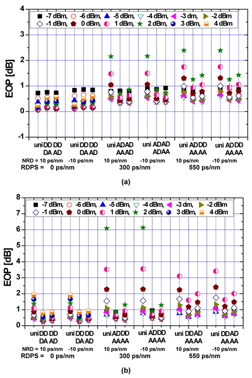
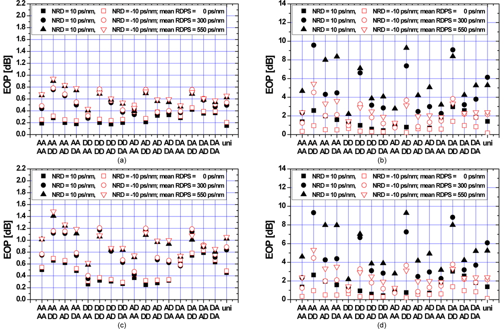
Investigating EOP characteristics depending on artificial distribution patterns for other link conditions, such as the optimal NRD, average RDPS, and dispersion coefficient of the DCF used is needed. Fig. 3(a) and (b) show the best and the second best EOP characteristics depending on the artificial distribution as a function of the launch powers, in cases of a -100 and -50 ps/nm/km dispersion coefficient of DCF, respectively. Fig. 3(a) and (b) also show the EOP characteristics in the uniform distribution for the performance comparison. Comparing Fig. 3(a) and (b) shows that it is advantageous to use a DCF with a -100 ps/nm coefficient for excellent system performance, regardless of the launch power, average RDPS, or optimal NRD. The best artificial distribution patterns are obtained from ‘DD + DA’, ‘AD + AA’, and ‘AD + AA’ for an average RDPS of 0, 300, and 550 ps/nm, respectively, in the optical links with a -100 ps/nm/km dispersion coefficient of the DCF. And, in the optical links with
The most significant result from Fig. 3 is that the best artificial distribution pattern mainly depends on the average RDPS. That is, the particular artificial distribution pattern selected for the average RDPS can improve the system performance beyond the uniform distribution; however, it is difficult to apply exactly the best pattern to all of the optical links because of the different link conditions. Thus, inducing the best artificial distribution pattern applicable to any system parameters is needed. Fortunately, not only one artificial distribution pattern is superior to the uniform distribution. Thus, it is expected that the best artificial distribution pattern for any optical links with all considered RDPSs and optimal NRDs can be induced.
Fig. 4(a)-(d) show the EOPs of the worst channel in the optical links with the optimal NRDs as a function of the artificial distribution patterns and the uniform distribution for a -3 and 2 dBm launch power and a -100 and -50 ps/nm/km dispersion coefficient of the DCF, respectively. It is confirmed that the best artificial distribution pattern, i.e., the pattern less affected by the average RDPS, is obtained to ‘DD + AA’, that is, the gradually descending distribution of the SMF lengths and the gradually ascending distribution of the RDPS in both half sections, for all optimal NRDs and all dispersion coefficients of the DCF.
Other notable results shown in Fig. 4 are that the optimal NRDs for the relatively low power and the relatively high power are 10 ps/nm by pre-compensation and -10 ps/nm by post-compensation, respectively; however, the ‘DD + AA’ pattern is independent of these characteristics.
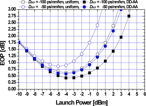
Fig. 5 shows the EOP of the worst channel as a function of the launch power in the optical links with a ‘DD + AA’ pattern and a uniform distribution, under the conditions of a 550 ps/nm RDPS and -10 ps/nm optimal NRD by post- compensation. We confirmed that the EOP characteristics depending on the launch power in the ‘DD + AA’ pattern are also better than those of the uniform distribution. In fiber communication systems, a 1-dB EOP is used for the system performance criterion, which is equivalent to the pulse broadening (the ratio of the received pulse root-mean-square [RMS] width to the initial pulse RMS width) of 1.25 and corresponds to a 10-12 bit error rate [17]. The launch power result of the EOP below 1 dB is defined as the effective launch power range in this study. From Fig. 5, the effective launch powers in the ‘DD + AA’ pattern are improved by almost 2 and 3 dB over the uniform distribution in cases of
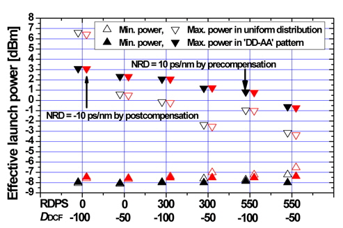
Fig. 6 shows the effective launch power as a function of the average RDPS and dispersion coefficient of the DCF used in the optical links with a ‘DD + AA’ distribution pattern at the optimal NRDs. It is confirmed that the effective launch powers for the average RDPSs and dispersion coefficients of the DCF in the ‘DD + AA’ distribution are better than those obtained in the uniform distribution, except for the optical links with a 0 ps/nm average RDPS and
This paper discussed the possibility of a flexible configuration of optical links with OPC and DM adopting an artificial distribution of the SMF length and RDPS. It was shown that the impairment of system performance due to GVD and the nonlinearity effects of the fiber in the optical links with the uniform distribution could be mitigated by applying particular artificial distribution patterns for the SMF length and RDPS to the OPC and DM links.
Furthermore, ‘DD + AA’ pattern among the artificial distributions, that is, the gradually descending distribution of the SMF length and gradually ascending distribution of the RDPS in both half sections, was the best configuration of the link for improving the system performance, regardless of the optimal NRDs, average RDPS, and dispersion coefficient of the DCF used. Consequently, through this study, it was confirmed that the flexible configuration of optical links is possible by applying artificial distributions of the SMF length and RDPS.