Metamaterials, which have been of interest in the fields of physics and engineering for the past several years, are artificial composite materials with negative indexes of permittivity or permeability. Recently, metamaterials with epsilon near zero (ENZ) have been investigated for interesting phenomena, such as supercoupling, transparency, cloaking devices, and highly directive antennas at microwave and optical frequencies [1-3]. The rapid growth and significant attention paid to ENZ materials is because of their ability to achieve a very long wavelength, allowing for the propagation of a “static-like” character of the electromagnetic field.
Silveirinha and Engheta [4] investigated the theory of supercoupling, squeezing wave energy, and field confinement in narrow channels and tight bends using ENZ materials. Previous studies [5,6] have experimentally demonstrated ENZ materials that exhibit supercoupling and energy squeezing using a microwave waveguide. These effects can be applied to a waveguide bend, an antenna matching circuit, a microwave filter, and a dielectric sensing application [1,7-9]. These technologies have a potential advantage for miniaturization because the electromagnetic energy is tunneled at the specific frequency through a narrow waveguide regardless of the total length of the ENZ channel. Radiation loss can be reduced, as compared with other metamaterials, because these technologies are based on a microstrip and waveguide shape. The tunneling frequency is near the cut-off frequency of the dominant mode in the waveguide. In order to minimize the size of a waveguide device, an ENZ channel can be used by a double-ridge rectangular waveguide (RWG) that has a lower cut-off frequency, instead of a general RWG [10,11].
In this paper, we introduce an ENZ tunneling circuit using a double-ridge RWG and we explain the structure of the proposed ENZ channel. The cut-off frequency of the double-ridge RWGs, including a general RWG, is calculated. For the ENZ tunneling circuit using a RWG and a double-ridge RWG, scattering parameters were obtained using the commercial finite element method simulator, Ansoft high-frequency structure simulator (HFSS) software [12]. We discuss in detail two types of transmission resonance phenomena, such as zeroth-order resonance (ZOR) and Fabry-Perot (FP) resonance, from the results obtained in the simulations. We also explain the approach adopted for extracting the constitutive parameters (effective permittivity, permeability, wave impedance, and propagation constant) of the ENZ channel from the scattering parameters using the retrieval method based on an RWG [13].
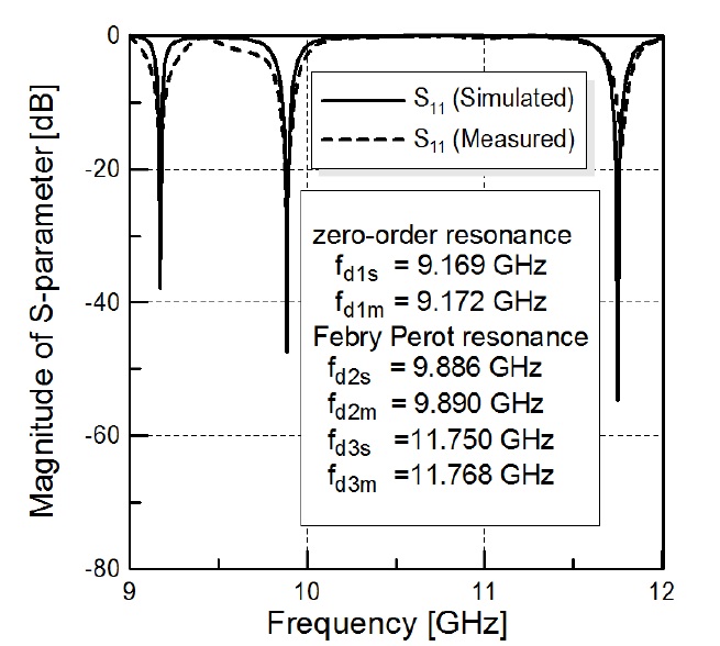
Using the extracted constitutive parameters, we explain that the proposed ENZ tunneling circuit using a doubleridge RWG is an ENZ channel, and we discuss, in terms of impedance matching, what electromagnetic energy is tunneled at the tunneling frequency. The measured results of the fabricated ENZ tunneling circuit were quite similar to simulated results, with tunneling frequencies being 9.169 GHz (simulated) and 9.172 GHz (measured).
Ⅱ. STRUCTURE OF THE PROPOSED ENZ TUNNELING CIRCUIT AND THE RESONANCE PROPERTIES
1. Description of the Structure of the Proposed ENZ Channel
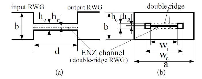
Fig. 1 shows the geometrical structure of the proposed ENZ tunneling circuit, where the ENZ channel is centrally located in the input-output RWG (IORWG, WR-90) with a cross section of
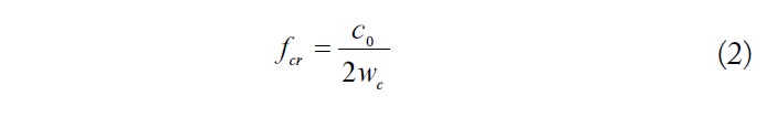
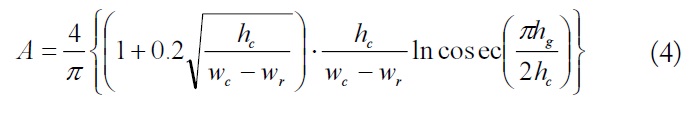
The ratio of the height of the IORWG to that of the proposed ENZ channel is very high, given as follows:
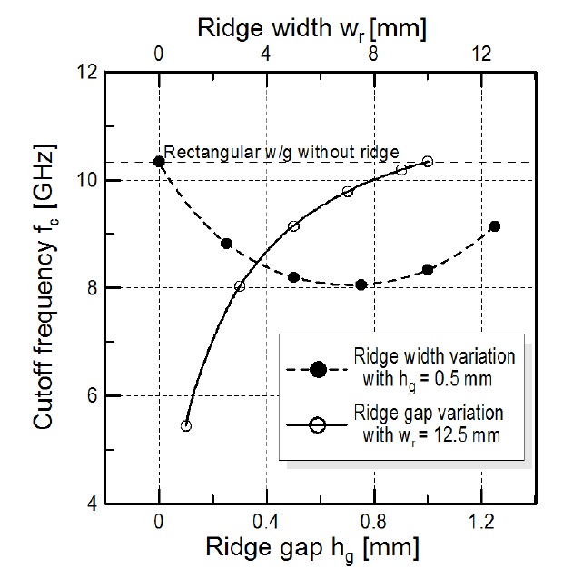
Compared to RWGs, ridge waveguides [10,11] have the advantages of a wide fundamental-mode operation bandwidth, a low cut-off frequency, and low wave impedance. In the ENZ channel, the cut-off frequencies of the RWG and the double-ridge RWG are as follows:
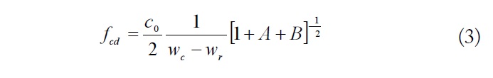
with
and

where
The cut-off frequency of the ENZ channel without the double-ridge is 10.338 GHz. As the gap of the ridge
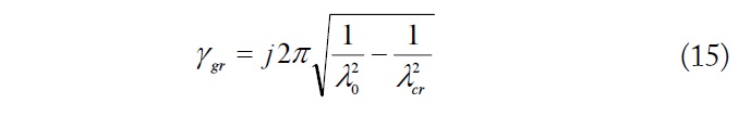
The guide wavelength
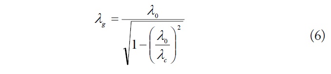


where
2. Scattering Parameters and Extraction of Constitutive Parameters
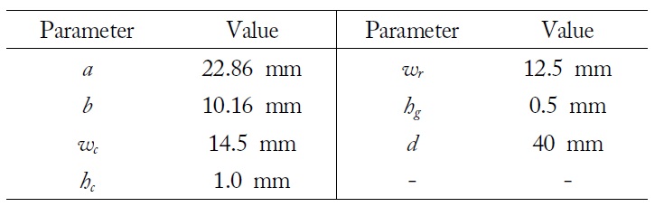
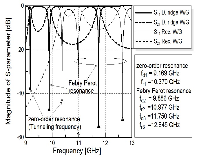
Let us consider the reflection and transmission properties of the ENZ channel using an RWG and a double-ridge RWG. First, to obtain scattering parameters, the ENZ channel using an RWG at an operating frequency of 10.370 GHz was created to test tunneling phenomena with a fullwave simulator, based on the finite element method, Ansoft HFSS. The results were processed by de-embedding from each port of the IORWG to the interfaces of the ENZ channel. The IORWG uses a standard WR-90 RWG. Table 1 lists the dimensions of the standard RWG and the proposed ENZ channel waveguide applied to a resonator of near-field microwave microscopy. The cut-off frequency
[Table 1.] Dimensions of the proposed epsilon near zero (ENZ) channel waveguide

Dimensions of the proposed epsilon near zero (ENZ) channel waveguide
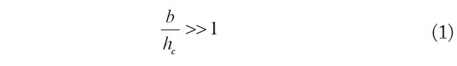
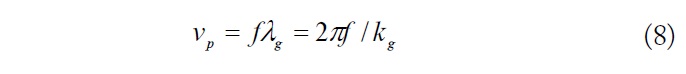
Because the frequencies are near the cut-off frequency of each ENZ channel (10.336 and 9.152 GHz), the guide propagation constant is close to zero, implying that the length of the ENZ channel is insensitive because the guide wavelength is very long. These resonances are of the ZOR type. The ZOR mainly depends on the transverse cross-sectional shape, which is related to the cut-off frequency of an ENZ channel. Other resonant frequencies of the ENZ channel using the RWG and the double-ridge RWG are (

( n = 1, 2, 3, ...). The wavelengths of the channel using the RWG and the double-ridge RWG are 81.2mm (at

, because of the shunt susceptance for the stored electromagnetic energy at the interface of the IORWG and the ENZ channel.
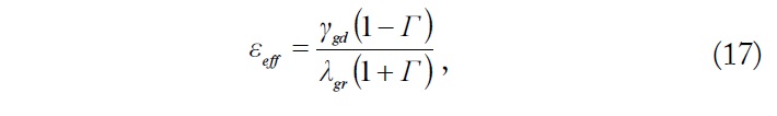
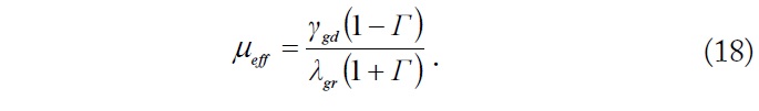
The effective permittivity
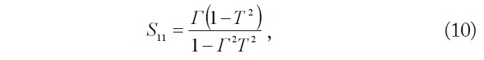
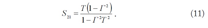
Eqs. (10) and (11) can be solved for
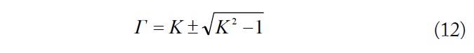
with
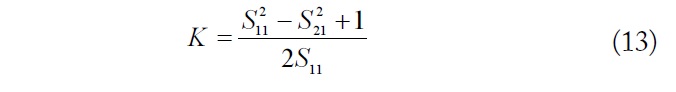
and
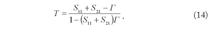
In Eq. (12), the sign of the square root has to be chosen such that

where
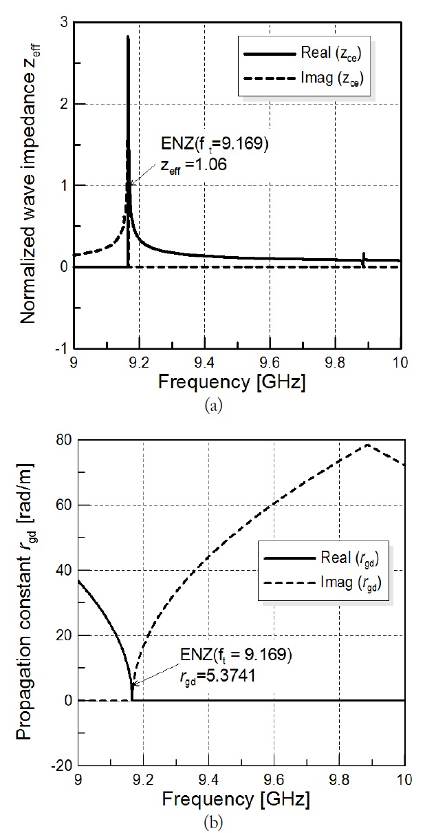
The effective wave impedance of the ENZ channel is where
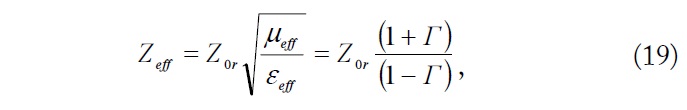
and

At the tunneling frequency
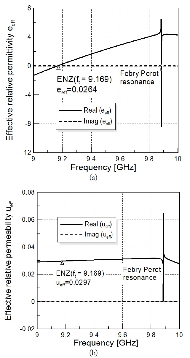
The extracted effective permittivity
In Fig. 4(a), we note that the proposed structure is the ENZ channel, because the real value of the effective permittivity
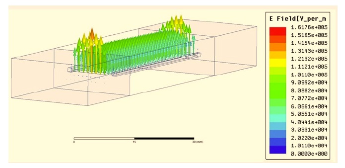
Fig. 6 shows the field distribution along the channel at the tunneling frequency, which exhibits little phase shift along the channel.
Ⅲ. FABRICATION AND MEASUREMENTS OF THE ENZ CHANNEL
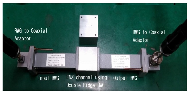
Aluminum was used for the ENZ channel circuit. The ENZ channel using the double-ridge RWG was manufactured using a wire electro-discharge machine, as shown in Fig. 7. The IORWGs, which were the size of a WR-90 standard waveguide, were connected to the ENZ channel using separated screws. The ENZ tunneling circuit for characteristic measurements was connected to a network analyzer (Anritsu 37397C) through a coaxial waveguide adapter, which differs from the waveguide port used in the simulation to compute the input reflection coefficient (
This causes small differences between the measured and simulated input reflection coefficients, as shown in Fig. 8. The measured tunneling frequency
In this paper, we proposed an ENZ tunneling circuit using a double-ridge waveguide for the miniaturization and field confinement of waveguide circuits and the characteristics of that system were analyzed. The proposed ENZ channel which was centrally located in a standard RWG, used a narrowed double-ridge RWG. The tunneling frequency of the proposed ENZ channel can be reduced to near the cut-off frequency of the IORWG. From the extracted parameters, the proposed double-ridge waveguide channel must become the ENZ channel because the effective permittivity is zero at the cut-off frequency and close to zero at the tunneling frequency. The normalized effective wave impedance is almost "1" at the tunneling frequency, implying that we have verified that the electromagnetic energy was tunneled. The measured scattering parameters of the proposed ENZ channel agreed with the simulation results, which had tunneling frequencies of 9.169 GHz (simulated) and 9.172 GHz (measured). In the future, we will apply an ENZ channel using a double-ridge waveguide to the probe antenna of a nearfield microwave microscope.