Nuclear energy is currently the most feasible option in Korea for providing for the energy demand in a sustainable manner, even though the accident at Fukushima in Japan occurred. However, an inevitable consequence is the production of high level radioactive waste during the utilization of a nuclear power reactor. In 2009, more than 10,000 tons of spent fuels were stored in nuclear power reactor site pools in Korea. Every year, about 700 tons of spent fuels are newly produced. The amount of spent fuels will soon reach the maximum storage capacity of the pools.
Nuclear spent fuel emits intense radiation. Therefore, a direct assay of fissile materials in spent fuel has many difficulties in real application. There are several existing technologies that can be used to analyze the fissile contents in spent fuel[1]; delayed neutron counting method, curium measurement, neutron die away time method, passive multiplicity counting, neutron albedo reactivity, and x-ray fluorescence. However, most technologies do not have a direct isotopic fissile analysis for spent fuel. Some technologies still need the help of burnup codes and further development for the approval to induce the fissile content. However, LSDS has a positive feature for the direct assay of isotopic fissile content in spent fuel[2,3,4,5]. It is not influenced by the intense radiation background (neutron and gamma rays) from spent fuel.
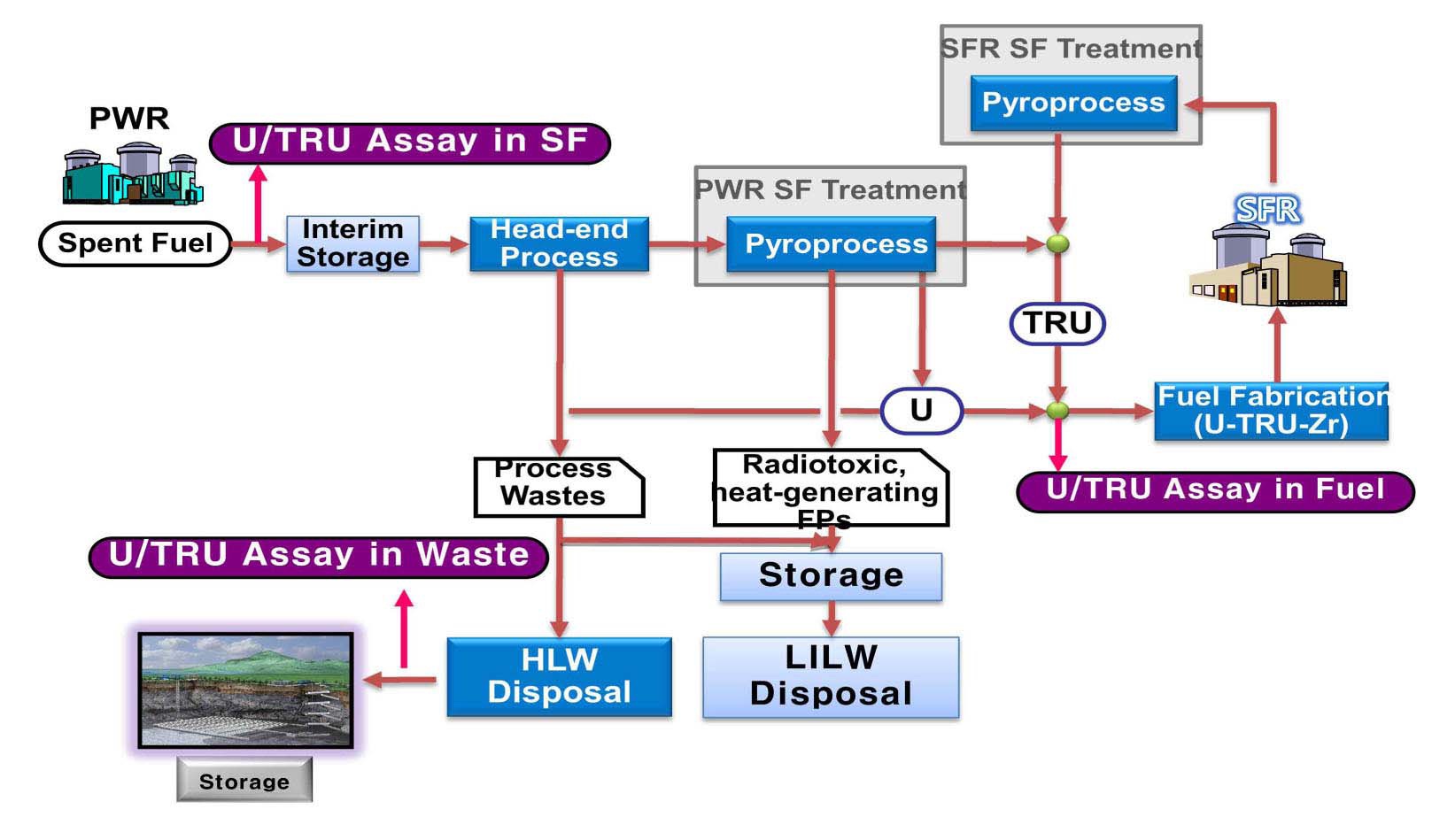
Generally, the spent fuel from a PWR has unburned ~1 % U235, produced ~0.5 % plutonium from the decay chain, ~3 % fission products, ~ 0.1 % minor actinides (MA), and a uranium remainder[6]. About 1.5 % of the fissile materials still exist in the spent fuel. One option to reduce the volume and radiotoxicity of PWR spent fuels and to produce energy is to use an SFR linked with the pyroprocess. The pyro-process produces uranium and uraniumtransuranium (TRU), mainly a plutonium, neptunium, plutonium, and americium, mixture with some fission products from PWR spent fuel. The produced nuclear material is a very self resistant feature in nuclear proliferation. A SFR fuel rod is fabricated from a uranium-TRU mixture. Therefore, an assay of fissile material content in the fuel resource material is very important for safe SFR fuel development and economical reactor operation.
The new assay technology for the isotopic fissile material contents in the pyro- process is under development at KAERI[2,3]. LSDS is the most feasible technology among the non-destructive techniques to analyze isotopic fissile material content directly. LSDS is very sensitive to distinguish fission signals from each fissile isotopes. Moreover, LSDS does not need burnup history information or burnup code help. LSDS has several features: direct fissile assay, near real time fissile assay, no influence from radiation background, fissile isotopic assay (not gross total fissile), and is applicable to spent and recycled fuel.
Several calculations were done on the designed spectrometer geometry[7]. The detection sensitivity was examined with respect to the position and distance. The neutron energy spectrum was investigated in the neutron slowing down energy. The neutron fission characteristics were analyzed in the slowing down time with the typical pyroprocess materials. A self shielding and multiplication effect was investigated in the energy region. Especially, neutron production mechanism was decided and described.
An isotopic fissile assay using LSDS is also applicable for the optimum design of spent fuel storage and maximization of burnup credit. Another important application is to verify the burnup code and provide a correction factor for improving the fissile material content, fission product content and theoretical burnup. Moreover, the advanced fissile assay technology will increase the international transparency and credibility in future nuclear energy system development. The accurate fissile content of spent fuel is very important information for efficient and economical spent fuel management as well.
2. LEAD SLOWING DOWN SPECTROMETER
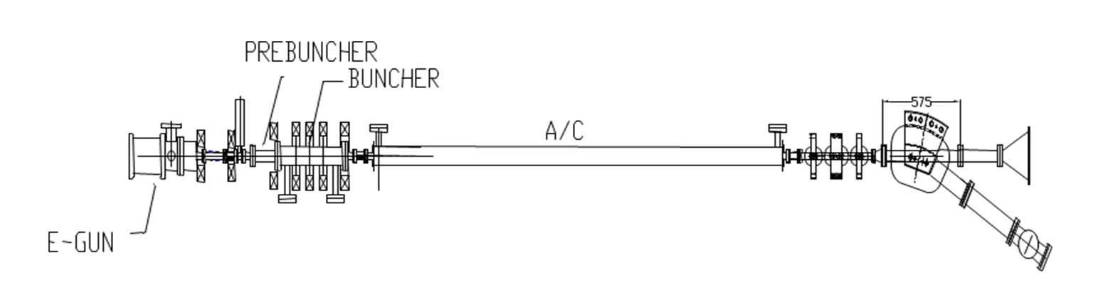
The lead spectrometer consists of several major parts: a lead slowing down spectrometer, neutron source generation, radiation detection, and data processing and analysis. An intense neutron generator is required to obtain the direct fission signal from the fissionable materials (uranium and plutonium isotopes) and receive enough detection statistics without background interference. As a source neutron, ~1012 n’s/sec was proposed using a one section electron linear accelerator with a proper target design[8,9,10]. The neutrons were produced in a Tantalum or Tungsten target material which has multiple layers with different thicknesses to maximize the bremsstrahlung radiation and neutron production. A gap between layers was considered for a target material cooling.
The principle of LSDS is very simple. A source neutron slows down continuously in a lead medium. An interrogated neutron induces energy dependent characteristic fission from isotopic fissile materials in a fuel assay area. Fortunately, an individual fissile material has its own fission characteristics below an unresolved resonance energy range. A threshold fission chamber screens the prompt fast fission neutrons of fissionable materials in a complex radiation field. The fission detector is insensitive in a gamma background. The detected signals have a direct correlation with the content of each fissile material.
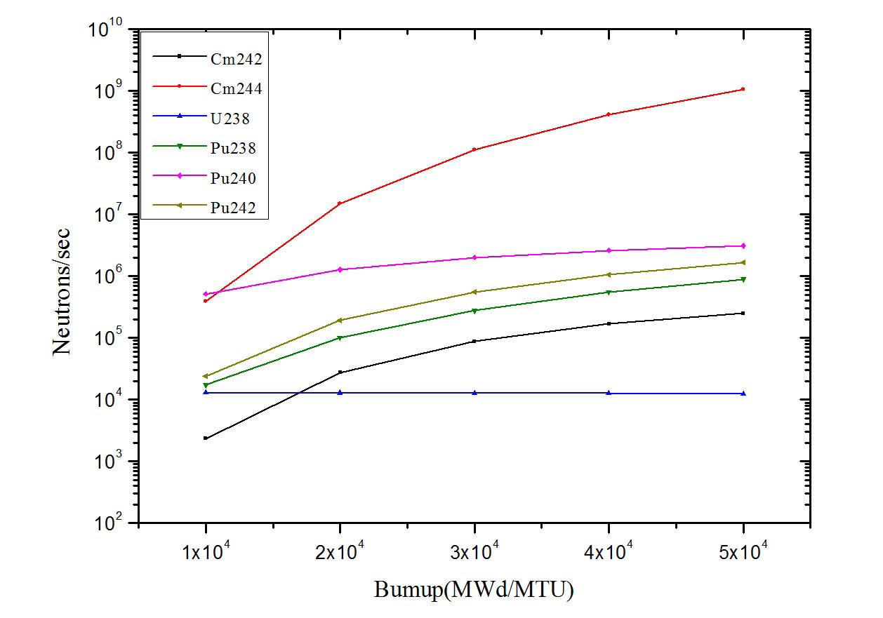
The pyro-process material has a spent fuel property even though several fission products are extracted in the process. It has intense neutron emission by spontaneous fission and (α, n) reaction[6]. The major neutron emission is from curium[6]. Therefore, the intense neutron emission will be a barrier in a direct content assay of isotopic fissile material. Fig. 1 shows the neutron emission rate in the major materials by burnup. As the burnup increases, the neutron emission increases as well. Especially, the neutron by Cm244 is 100 times greater than other major neutron emitters. Therefore, curium will be accumulated more at a higher burnup.
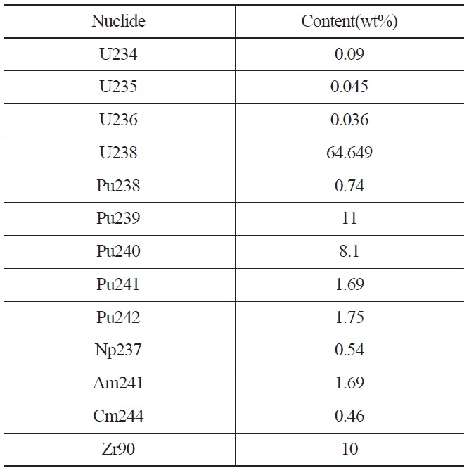
For the pyro-process material simulaiton, 11wt% Pu239, 8.1wt% Pu240, and 1.69wt% Pu241 are presented. The composition of the pyro-process material for simulation is summarized in Table 1. A relatively small amount of Np237 and Am241 is also presented. The fuel assay area
[Table 1.] Composition of Pyro-process Material for the Simulation

Composition of Pyro-process Material for the Simulation
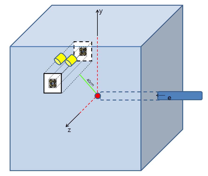
is located 40cm away from the neutron source in the lead. The source neutron, having ~0.5MeV mean energy, slows down in the medium and induces fissile fission with respect to the slowing down energy. The fission neutron by fissile isotopes is detected at the threshold fission chamber. Fig. 2 shows the LSDS system. The neutron source is located at
the center of lead cube and the detector is above the fuel assay area.
2.2 Lead Spectrometer Analysis
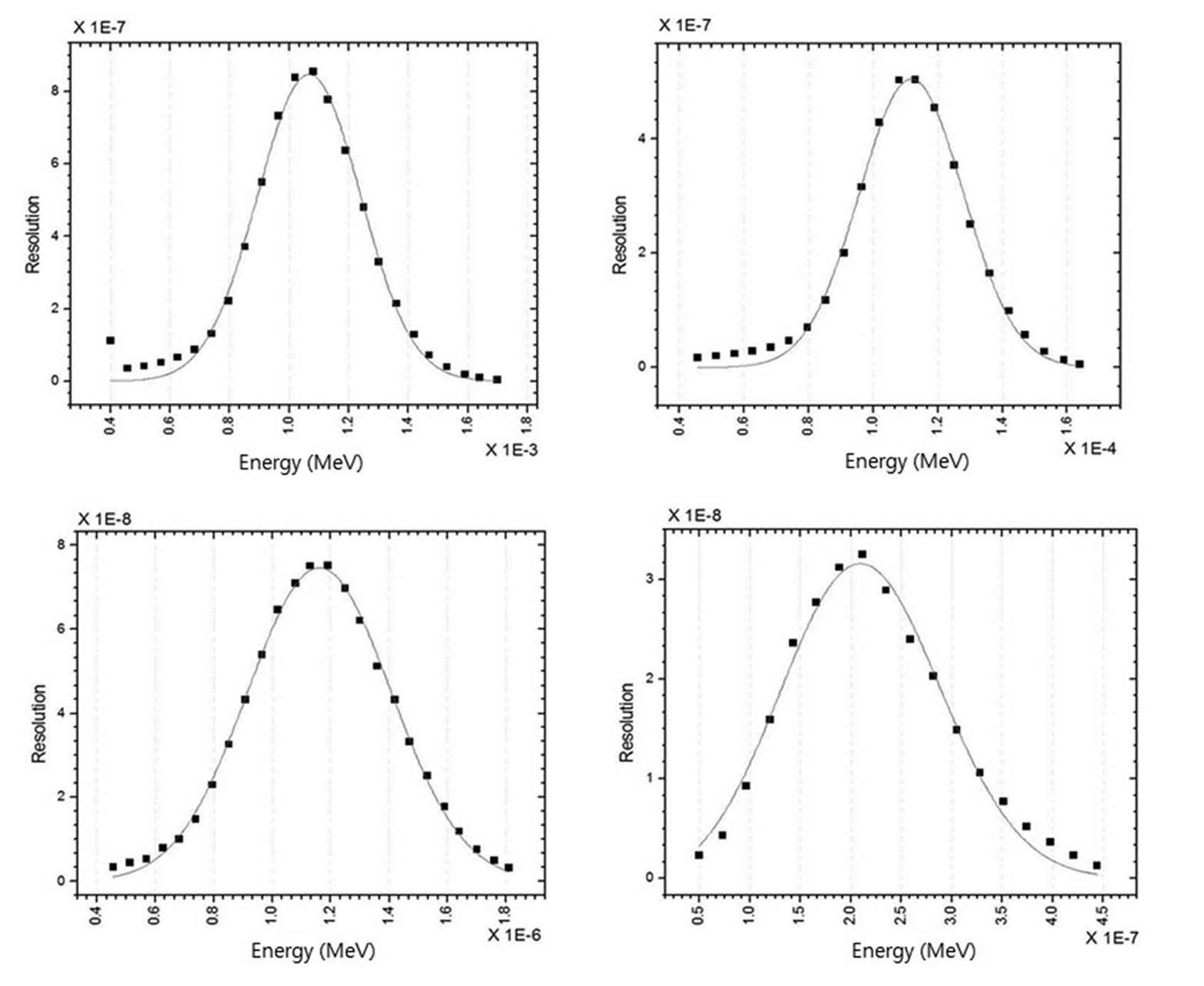
The neutron spectrum must be well organized in the spectrometer fuel assay area from high to low energy to get the individual fissile fission signature. Therefore, in a lead spectrometer, a neutron energy spectrum was evaluated from keV to eV energy range[7]. The energy spectrum has a direct relationship with isotopic fissile fission. A narrow spectrum is preferable to discriminate isotopic nuclear fission. Fig. 3 shows the energy spectrum fitting with respect to the slowing down energy, 1keV, 100eV, 1eV, and 0.1eV. The distribution follows a Gaussian shape well. Until 1eV, the spectrum shows a good shape and resolution of ~30%, however, at 0.1eV, it shows a broadened property of ~50%. However, the extent of broadening is not severe. Therefore, considering the energy spectrum, 1keV to 1eV might be a good energy region.
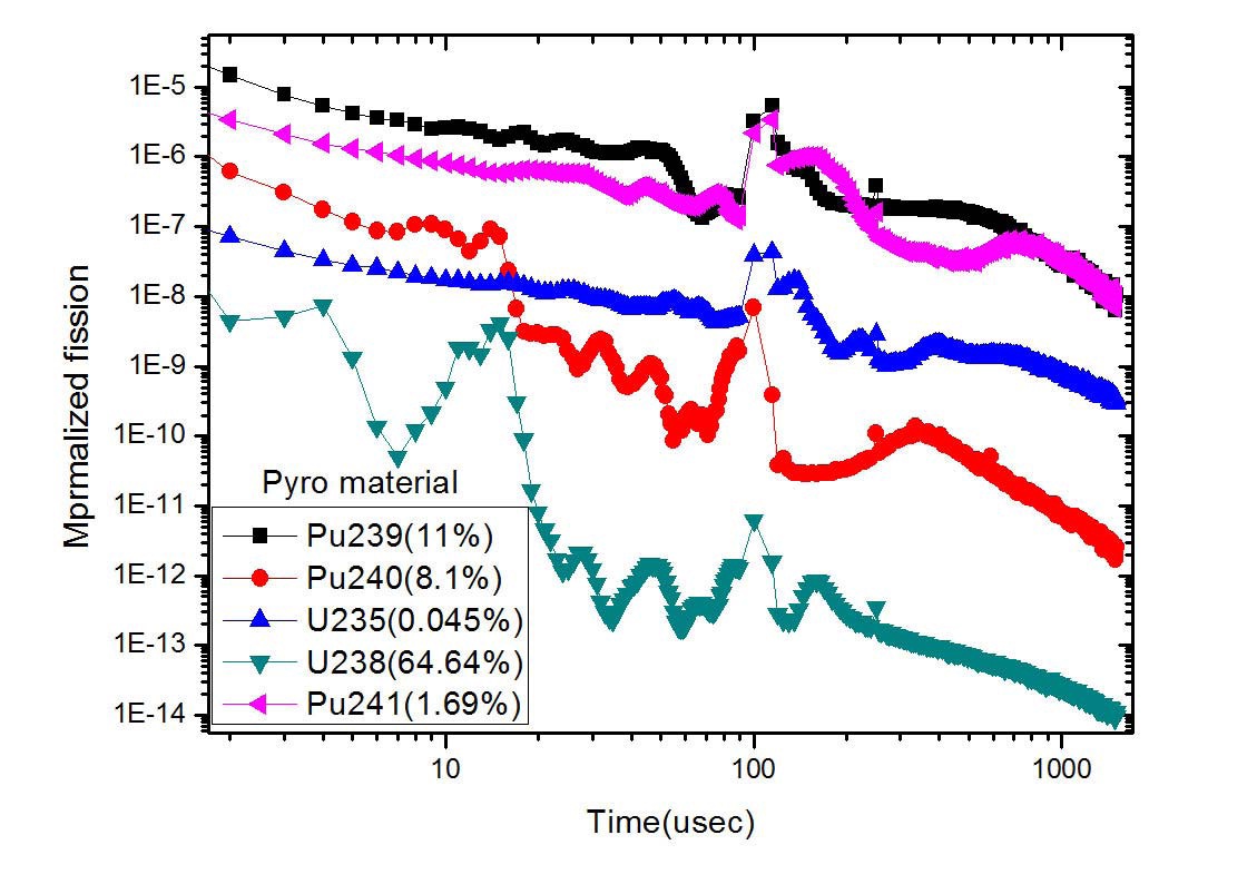
The external neutron source slows down in a lead medium. The continuous interrogation neutron energies are obtained and the neutrons finally enter into the fuel. Prompt fast fission neutrons with respect to the fission characteristics of fissile materials(U235, Pu239 and Pu241) can be detected at the surrounding neutron detectors[7]. In the fuel area, the fission characteristics of the fissile were investigated in 2by2 fuel rods. The fissile fission in fuel is expressed as below,
where ν(E) is the fission rate and ϕ(E) is the source neutron arriving at the fuel. Fig. 4 shows the fission signature produced by each fissile material at the slowing down time. U235 has a big resonance of around 150, 250, and 400 µsec, and 50, 130, and 600 µsec for Pu239. Pu241 has a big resonance at 100, 170, 800 µsec as well. After 20 µsec, the fissile material shows its own fission property, specially, around 100 µsec and from 500 to 600 µsec, the fission characteristics of the isotopic fissile material are dominant. From the figure, generally, it can be seen that 20 to 600 µsec is a good choice for a fissile assay. Therefore, LSDS is very sensitive for getting the induced fission signal from the isotopic fissile content. However, self shielding must be considered, because dominant fission has relatively large neutron absorption at the neutron energy.
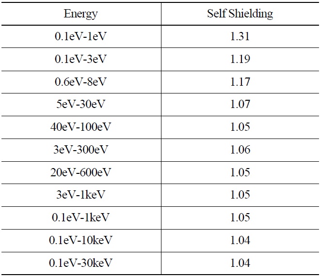
A self shielding parameter was calculated at the 2by2 fuel geometry by introducing the pyro-process produced nuclear material as shown in table 1. When nuclear material is inserted into the assay area, the pyro-process recycled fuel material perturbs the spatial distribution of slowing down neutrons in lead and prompt fast fission neutrons produced by fissile materials are also perturbed. The self shielding factor is interpreted as how much of the absorption is created inside the fuel area when it is in the lead[7]. The self shielding effect provides a non-linear property in the isotopic fissile assay. When the self shielding is severe, the assay system becomes more complex and needs a special parameter to treat this non-linear effect.
Table 2 shows the self shielding results for the pyroprocess produced material. U238 is used as a base material
for fabricating SFR fuel. Therefore, the energy range in Table 2 covers the dominant absorption energy. From the results, it can be seen that the effect is relatively large at low neutron energy. In particular, at 0.3eV and 1eV, Pu239 and U235 have dominant fission characteristics. However, as the energy range becomes larger, the self shielding shows a lesser effect. In the largest energy range, the self shielding is less than 10%.
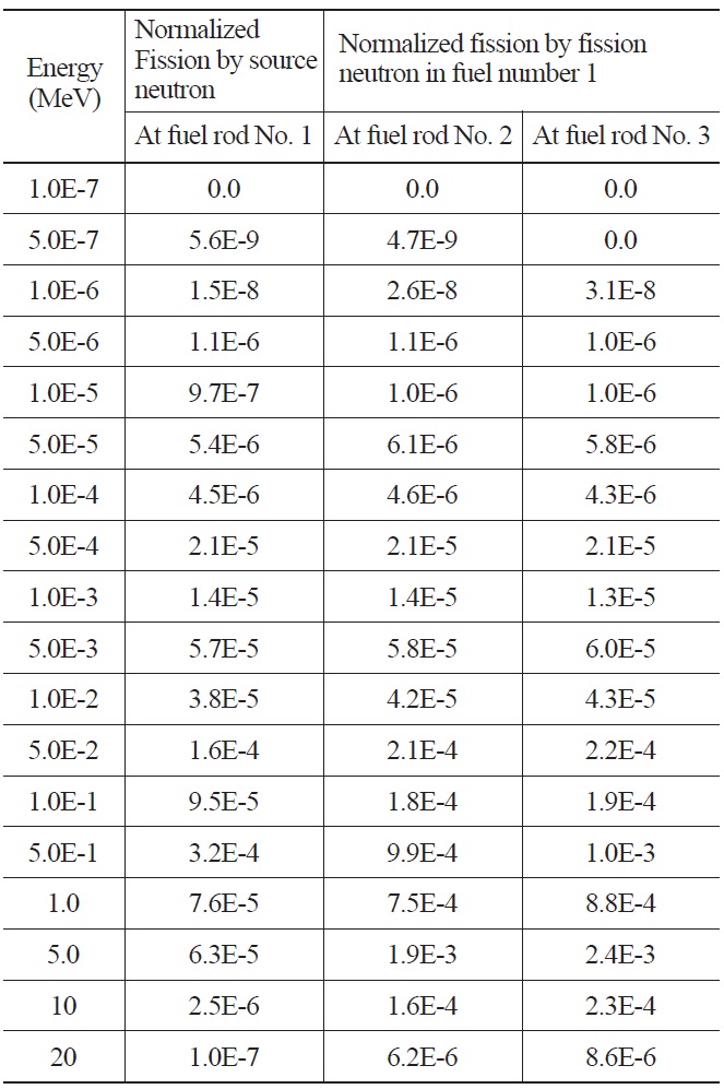
In order to understand the fission neutron contribution in the spectrometer, the multiplication effect by a fast fission neutron was investigated[7]. An induced neutron contributes to secondary fission in the fuel assembly because the pyroprocess material has highly enriched plutonium isotopes with uranium. Table 3 represents the normalized fission neutrons by source neutrons at fuel rod number 1 in 2by2
[Table 2.] Self Shielding Effect with Respect to Neutron Energy for the Pyro Process Material

Self Shielding Effect with Respect to Neutron Energy for the Pyro Process Material
geometry and the normalized fission neutrons at adjacent fuel rods, numbers 2 and 3, by the neutrons produced in rod number 1. From the table, it can be seen that the normalized fission neutron production at the adjacent rods by the fission
[Table 3.] Normalized Fission Neutron

Normalized Fission Neutron
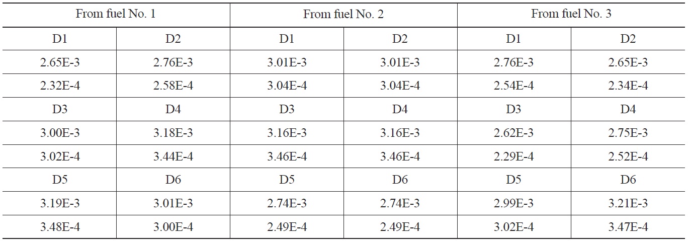
[Table 4.] Normalized Fission Neutron Arrival and Detector Response

Normalized Fission Neutron Arrival and Detector Response
neutron in rod number 1 is very small, thousands of times less. Therefore, the multiplication effect can be neglected in 2by2 pyro assembly.
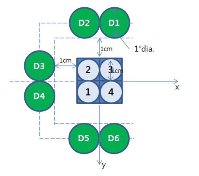
The lead spectrometer has a very complex and intense radiation fields: from the spent fuel itself and from the neutron source generation system. Therefore, in the complex radiation field, how to collect the direct prompt fast fission neutron from fissile material is very important. Therefore, the detection sensitivity was examined at the surrounding detectors[7], as shown in Fig. 5. The fission threshold detectors are a good choice for detecting the prompt fast fission neutrons. In Fig. 5, the threshold detector is located as close as possible, 1cm away from fuel assembly surface. The detected signals are expressed as

where
detectors, and the detector threshold response. The results show the symmetrical response at the symmetrical detector position from the fuel rods. The surrounding detectors can get the fissile fission signals.
The source neutron is necessary to induce the isotopic fissile fission. Therefore, the source neutron must be intense and have good energy resolution in a wide energy range. The source neutron is produced by (e,
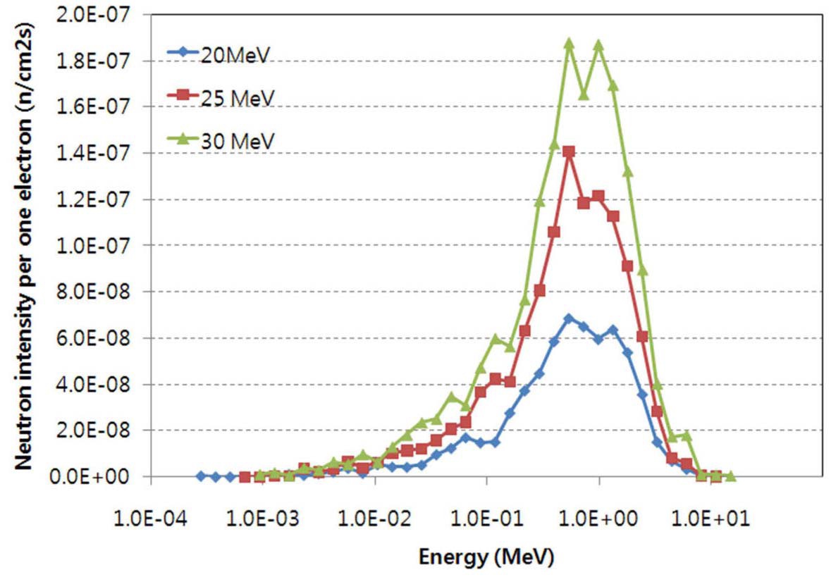
1MeV. The produced neutron energy spectrum is expressed as[7]

where T is the photonuclear target temperature in MeV, E is the neutron energy and c is the normalization constant. The neutron is produced per ~100 electrons at 30MeV in unit time. In order to overcome the neutron background, ~1012 n’s/sec is required and an ~2kw beam is expected. Therefore, a high current is necessary, ~500mA. Fig. 8 shows the produced neutron spectrum with respect to the neutron energy. A high energy electron produces neutrons with a less broadened spectrum.
A direct content assay of isotopic fissile materials has a good advantage in an LSDS system. The direct fissile assay is a very important key technology in the fuel cycle, similar to using PWR spent fuel for safety and economics. The LSDS is very applicable to assay isotopic fissile content in the pyro-process to fabricate an SFR fuel rod. The fissile material control must be approved for the fuel fabrication. Also, the technology is applicable to the spent fuel storage optimum design and burnup credit. Fig. 9 shows a summary
of the application of LSDS. Another application is the approval of fissile and fission product content and burnup for the burnup code. Many current nondestructive technologies have a limitation in a direct isotopic fissile assay. Therefore, LSDS will contribute to the approval of isotopic fissile content of an SFR-pyro linked fuel cycle as an international demand.
A lead slowing down spectrometer has been proposed to analyze the isotopic fissile content in recycled fuel. The new technology has good features for the direct analysis of the content of isotopic fissile material. The dominant feature of LSDS is not to be interfered from the spent fuel background. However, to overcome the background, an intense neutron source is required. Several calculations were performed to setup the optimized LSDS system. The neutron spectrum has a good shape until low neutron energy. The fission multiplication was low in adjacent fuel rods, and does not interfere in the detection of source neutron fission.
From the simulation, each fissile has its fission characteristics during the neutron slowing down process. This different fission signature is used for an isotopic content assay. Also, the signature is very proportional to each fissile content. Below 10keV the energy of interrogation neutron is proper to get each fission characteristic. However, below 0.1eV energy, there is no distinguishable dominant fission structures at each fissile. The fission detector is a good choice for resolving the fission characteristics of each nuclear material to distinguish the fission neutrons from background and source neutrons. The detected signals are used to produce isotopic fissile material content. However, an analysis of detected signals and detector designs is necessary for the actual application of a fissile content analysis in a spent fuel assembly. An LSDS system will play an important role in the fuel cycle development for safety and economics.
Moreover, by approving the isotopic fissile content, it will increase the proliferation resistance of the fuel cycle and provide transparency and credibility[10] of reutilization of nuclear materials.