The world then started investigations and researches for non-petroleum fuels to be less harmful to the environment and reduce the dependency on foreign energy imports. Biofuels are one of the suggestions; they are not new since Rudolph Diesel’s work was based on the use of vegetable oil as fuel for his invention (Knothe, 2001). The use of natural gas in internal combustion engines has been researched thoroughly to reach the optimum case in both engine performance and environmental impact. Both types of internal combustion engines were studied; the compression ignition and the spark ignition engines. All problems associated with the use of natural gas in these engines were dependent of the injection timing inside the engine cylinders and the cylinder geometry, accurate control is needed to avoid engine knocking and high emission formation levels. Lean burn concepts also were investigated to reach low emission conditions (Zhang and Frankel, 1998; Papagiannakis and Hountalas, 2004). Also the fuel cell power plant operated with hydrogen produced from natural gas through steam reforming processes to mitigate air pollution from ships (Welaya et al., 2012).
El gohary (2012) found that using natural gas as a fuel with the proposed marine gas turbine cycle at current HFO and natural gas prices provides the highest cost saving for a distance less than 4000 nautical miles (NM). With the expected changes in fuel prices, the proposed cycle achieves cost saving of 3% per round trip, and this saving is directly proportional to increasing fuel prices, compared to other options.
The marine field witnessed the introduction of natural gas fuel for diesel engines in LNG carriers recently where the boil off gas evaporated from the cargo is used in diesel engines instead of boilers as was the case for decades. Proposals to use gas turbines instead of diesel engines have been introduced but none was implemented in reality till now. Seddiek et al (2012) discuss high-speed crafts suffer from losing a huge amount of their machinery energy in the form of heat loss with the exhaust gases. This will surely increase the annual operating cost of this type of ships and an adverse effect on the environment.
It has been shown in the previous section that the use of natural gas or hydrogen instead of diesel in marine gas turbines is thermodynamically feasible, but to complete the investigation, the environmental feasibility is assessed by comparing the pollutant emissions for each of the cases under study.
Proton exchange membrane fuel cell generates electrical power from air and from hydrogen or hydrogen rich gas mixtures converting current hydrocarbon based marine fuels such as natural gas, gasoline, and diesel into hydrogen rich gases acceptable to the proton exchange membrane fuel cell on board ships as in (Welaya et al., 2011; 2012). In addition, solid oxide fuel cell is a high temperature fuel cell. At high temperature, warmed air enters the cathode side of the fuel cell and steam mixes with fuel to produce reformed fuel which enters on the anode side. Moreover, the combined solid oxide fuel cell-gas turbine is one of the combined systems which achieves high thermal efficiency (P?lsson et al., 2000).
Combustion of hydrogen inside internal combustion engines has been, and still is, the subject for many research programs in many countries. Like the natural gas, the main problems associated with the application of hydrogen in internal combustion engines include the engine knocking; air fuel ratio and intake temperature were find to be the main causes for this problem and their optimization is a must to have a knock free engine (Hailin and Ghazi, 2004).
Some problems were discovered to be only related to the hydrogen due to its special characteristics; these characteristics are the high flame speed and the low ignition energy, the problems associated are the steep rise of cylinder pressure and possibility of fuel pre-ignition leading to potential explosions inside the engine systems (Ma et al., 2003).
Regarding the emissions, it is evident that the hydrogen produces fewer emissions almost in all engine operating conditions, due to the higher combustion temperature in hydrogen engines, the NOx rates were found high in some cases and many solutions were produced, all of them use well proved technologies used nowadays with normal engines, these technologies include exhaust gas recirculation and catalytic reduction filters (Banwan et al., 2010; Tien et al., 2008).
Most of the researches done on hydrogen internal combustion engines have as result a slight increase in the engine thermal efficiency with a decrease in engine output power and torque (White et al., 2006; El gohary, 2013a).For the application of hydrogen in gas turbines, the scientific community witnessed many research programs and technical investigations to study the characteristics of hydrogen combustion inside gas turbine combustors. Basically there are three methods applied in the gas turbine market to reduce emissions from ordinary gas turbines powered by petroleum products or natural gas; dry low NOx combustors, flame dilution by the addition of steam or adding catalytic reducers at the exhaust systems. Not all of these techniques can be used with hydrogen due to its special combustion characteristics (Chiesa et al., 2005).
All researches have common conclusions; the direct substitution of natural gas or other fuel oils results in an increase in NOx levels and the reduction of these levels necessitates additional modification to be made to the combustor design in the dry combustor designs or increasing the rate of dilution achieved by steam addition (Ziemann et al., 1998; Dahl and Suttrop, 1998). Another resource thought to be the fuel of the future for decades is hydrogen gas. The scientific research concerning the use of hydrogen in transportation began shortly after the first oil crisis. Many car manufacturers started development programs to produce cars that could operate by hydrogen fuel in internal combustion engines (DeLuchi, 1989).
In order to achieve the maximum benefits from using the hydrogen, many ideas encouraged the use of blends of natural gas with hydrogen with different proportions either in internal combustion engines or gas turbines, the results for engines showed the improvement of the natural gas case when the emissions are considered, but for the gas turbines, the admission of hydrogen to natural gas in ordinary combustors without special measures to reduce NOx resulted in increased emission rates (Tomczak et al., 2002). For the short term development the natural gas provides ideal solution for the marine applications. Also, the thermodynamic performance using the natural gas in the gas turbine cycle was found to be close to the performance when diesel oil is used. With about 0.25% efficiency reduction at the ISO design conditions, the natural gas provides an excellent replacement for diesel. For the hydrogen, it was found that many modifications required to be made to reach the optimum performance. The gas turbine thermal efficiency was found to be 1% less in the case of hydrogen when compared with original case of diesel (El gohary, 2013a).
The challenges in designing high performance combustion systems have not changed significantly over the years, but the approach has shifted towards a more sophisticated analysis process. A technical discussion on combustion technology status and needs will show that the classic impediments that have hampered progress towards near stoichiometric combustion still exist. The paper presents the design for annular combustion chamber for annular gas turbine for 20 kW power generation wit kerosene as fuel and it’s also include the CFD simulation is carried out with the CFD tool ANSYS CFX (Chaudhari, 2012).
The predicted results of combustion and emissions are in well conformity with experimental results (Hussain et al., 2012). Gharehghani et al. (2012) shows that an increase in the initial swirl ratio lengthens the delay period for auto-ignition and extends the combustion period while it reduces NOx.
The gas turbine thermodynamic equations are computerized using Engineering Equations Solver (EES) program, where the thermodynamic properties of the substances under study can be easily obtained using the built-in functions and data. EES used for performing a modeling for LM2500 gas turbine. The modeling has been done assuming constant power output in both cases of natural gas and hydrogen. In other words, the performance of the engines is assessed on the basis of same power achieved. The program was used to show effect of the fuel properties on gas turbine performance assuming the initial conditions of inlet temperature and pressure are 15℃ and 1 bar respectively.
It is found from the study that gaseous fuels give good performance if compared to the diesel fuel. To achieve this performance, the engine’s compressor and turbines need to be modified to accommodate the different flow rates especially in the case of hydrogen where large differences in flow rates are observed. Although, it is expected that without modifications the performance of gaseous fuels will not be too much lower than the performance of diesel and this is proved by the wide use of natural gas in electric generation stations using gas turbines with natural gas.
It has been shown in the previous work for the author (El Gohary et al., 2013a; 2013b) that the use of natural gas or hydrogen instead of diesel in marine gas turbines is thermodynamically feasible, but to complete the investigation, the environmental feasibility is assessed by comparing the pollutant emissions for each of the cases under study.
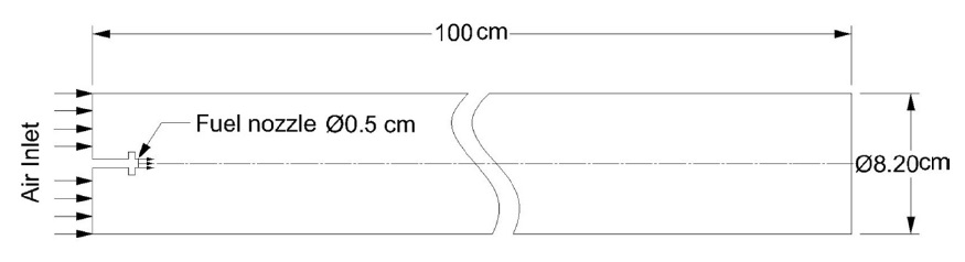
In order to do so, a simple combustion chamber is modeled to study the combustion of the three fuels using the commercial CFD code Fluent. The combustion chamber is a 1
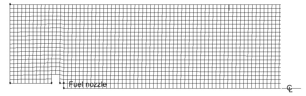
The model geometry was then meshed to create the zone of CFD computation. The meshing was done using the Gambit software with quad mesh type having the cells length equal to the shortest edge in the geometry (0.2
As shown in Fig. 2, only half of the combustion chamber is modeled since it is a symmetric zone, i.e. the computation done on the upper half will be mirrored to the lower half to get the complete solution. Also, just before the fuel nozzle, a small disc is added to the fuel nozzle to create enough turbulence which is needed to ensure a good air fuel mixture. Table 1 shows the inlet conditions for each of the three cases.
It has to be noted that since the combustion is almost at constant pressure, the combustion process can be regarded as incompressible and only the inlet velocity and temperature are required to define the boundary conditions for both air and fuel, therefore the inlet boundary conditions are set to velocity inlet zones.
The velocities have been determined according to the desired mass flow rate and the available inlet area, air and fuel flow rates are linked together by the total air fuel ratio for each case. The temperature of the air is that resulting from the compression process and the fuel is assumed to be injected at normal temperature.
[Table 1] Inlet boundary conditions.
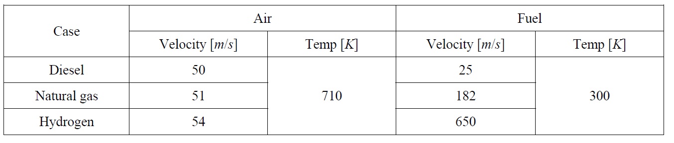
Inlet boundary conditions.
The model combustion chamber has a length to diameter ratio of 12.2 which is double the normal ratios for gas turbine combustors, this value was chosen due to the 2D identification of the problem, real combustion chambers have the main air stream split into primary, secondary and dilution zones which cannot be described in 2D simple models, so in order to have good air fuel mixing and complete fuel combustion the length of the combustion chamber’s model was increased. Also it has to be noted that the idea behind modeling the combustor is to compare the emission rates in the three cases in an approximate manner not to obtain accurate data about the combustion process.
The exit face of the combustion chamber was taken to be an outflow region where no specific conditions need to be defined; the solver extrapolates the required information from the interior zone.
After creating the geometrical model, defining the boundary conditions and setting the operating conditions for each case, the model is run to get the final solution. For this case the solver used was the 2D-steady-turbulent model already built-in inside the commercial CFD code.
The governing equations solved here include the equations for the conservation of mass, momentum and energy. Since the flow inside the combustor is turbulent, a turbulent model is used adding transport equations to the model. Also, to account for the fuel combustion, species conservation equations are solved.
The mass, momentum and energy equations are given next.
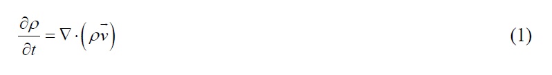
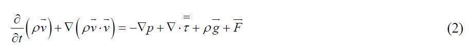
where

is the stress tensor, and

and

are the gravitational body force and external body forces respectively.

where keff is the effective conductivity and

is the diffusion flux of species. The first three terms on the right-hand side of the above equation represent energy transfer due to conduction, species diffusion, and viscous dissipation, respectively.
The turbulence model used is the
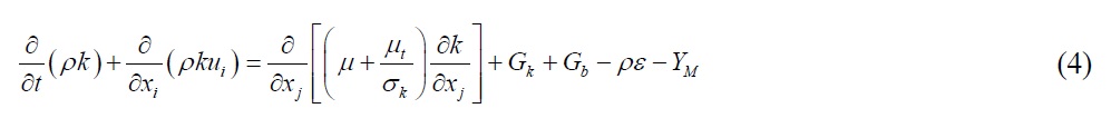

In these equations,
For the reactions, a species transport equation is solved for each species available.
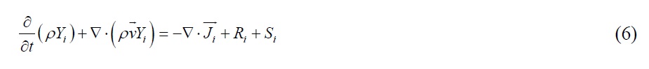
where
Huge amount of results data can be extracted from the CFD solution of such a case, but here only the most important are discussed. Those most important results include the following:
• Fuel concentration on the cylinder axis.
• Maximum temperature inside the combustion chamber.
• Average temperature on the exit face.
• Fractions of combustion products at exit face.
• Amount of pollutants per fuel unit mass.
• Amount of pollutants per unit heat input.
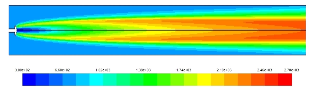
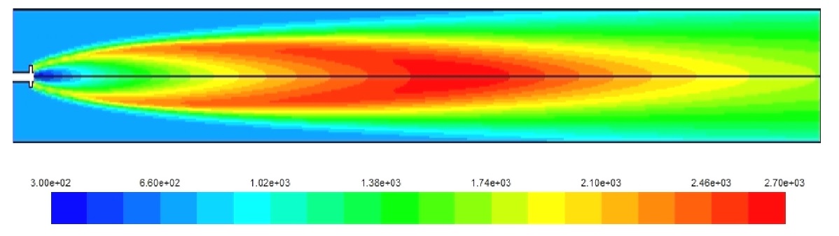
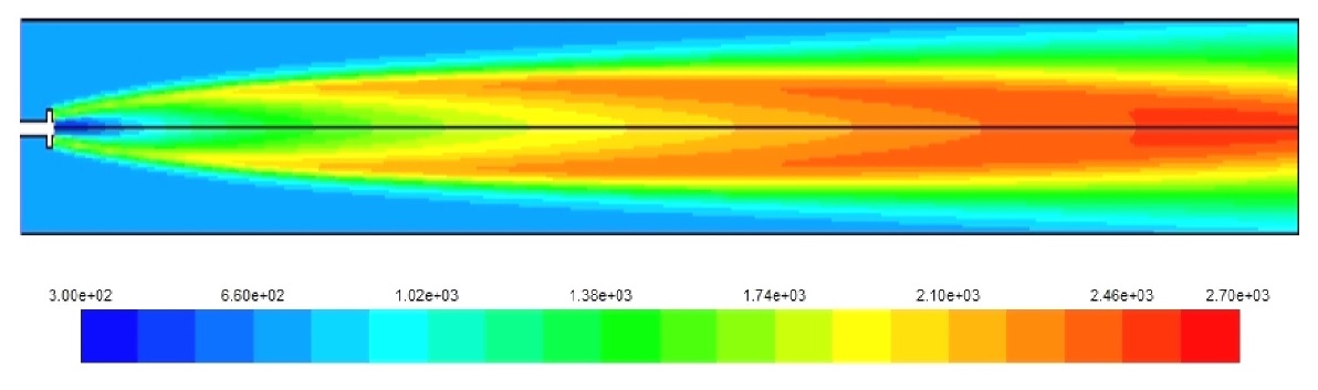
The visualization of the temperature distribution inside the combustion chamber is very important to determine the high temperature concentration zones, this is very useful in the design process of gas turbine combustors to avoid high NOx levels, measures can be taken to control the air flow inside the combustor to have better temperature distribution. In real combustion chambers, the dilution zone at the end of the combustion process plays an important role to limit the NOx formation rates by reducing the temperature of the combustion gases going to the turbine section of the engine.
Figs. 3-5 show the temperature distribution for the three cases under study. The hydrogen case has the highest combustion temperature and this causes a higher rate of NOx formation. Also, the higher combustion speed of hydrogen creates a self dilution zone even inside a simple combustor as the one modeled. Although, for diesel and natural gas the high temperature zone continues towards the end of the combustor necessitating a more complex design, and this is due to the slower combustion speed for these fuels compared to the hydrogen. it has to be noted here that the diesel fuel used in this model is in fact diesel vapor and not liquid diesel.
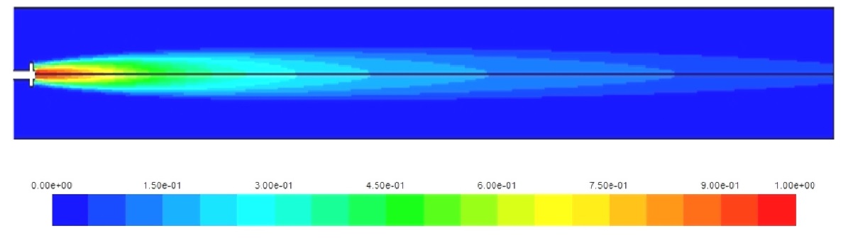
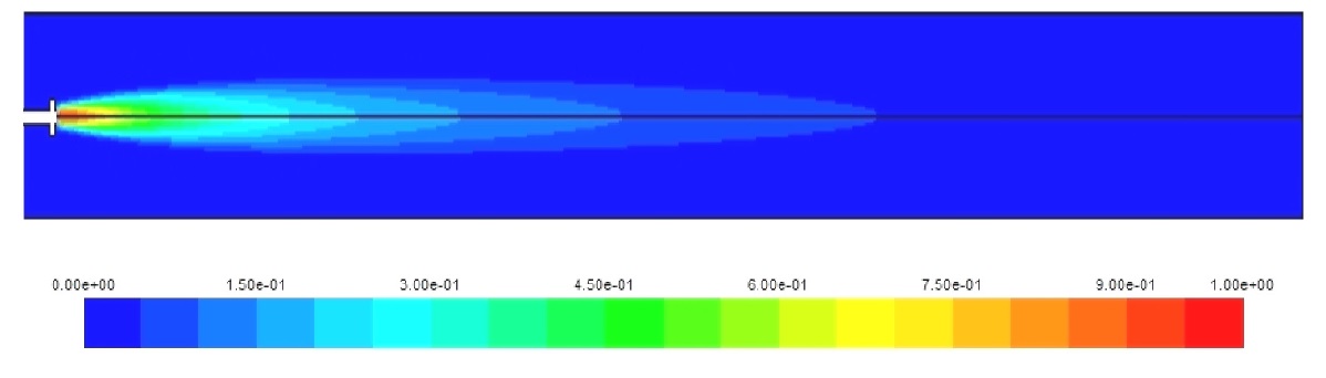
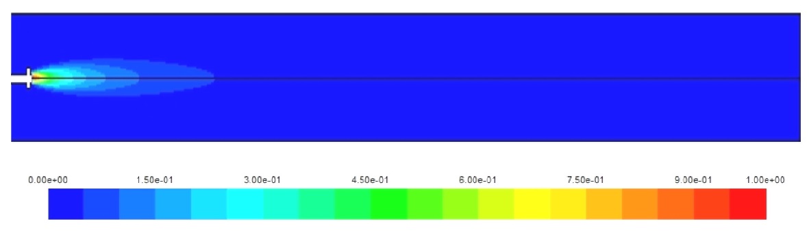
Figs. 6-8 show the concentration of the fuels along the cylinder axis. Again, the higher combustion rate of hydrogen helps in the complete combustion of the hydrogen amount injected; this is not the case for natural gas and diesel where a fraction of the fuel injected exits with the combustion products to the turbine. This leads to increased hydrocarbon pollutants expelled to the atmosphere which is added to the NOx and CO2 emissions.
The high combustion speed of hydrogen requires then a shorter combustion chamber modified to control the exit temperature, natural dilution happening after the combustion will waste a portion of the added heat and thus reducing the total efficiency of the engine. For real combustion chambers which are already shorter than the one under study, modifications to the distribution percentages of the main air stream entering the combustor will be required in order to reduce the percentage of dilution air.
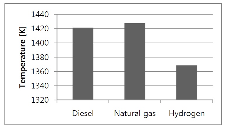
Fig. 9 shows the maximum temperature occurring due to the fuel combustion, as a rule, the higher the temperature the higher the NOx emission rates, so it was observed that the higher NOx levels were obtained in the case of the two gaseous fuels having higher temperatures than the diesel case.
At the end of the combustion chamber, the combustion gases are directed to the turbine section of the engine, the value of this turbine inlet temperature is very crucial to the performance of the gas turbine. Excess temperature requires extra turbine
blades cooling by extracting a portion of the compressed air from the compressor to cool down the blades, and on the other hand, reduced turbine inlet temperature causes an efficiency reduction. Fig. 10 shows the average temperature at the exit face of the combustion chamber.
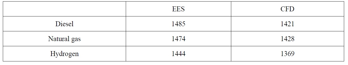
The exit temperatures for both diesel and natural gas are almost the same with only 0.5% increase, while for the hydrogen, 3.7% reduction is observed and this is due to the diluted combustion gases after the complete combustion of the hydrogen early inside the combustion chamber. This reduction will have a negative effect on the total efficiency of the gas turbine. It has to be noted that the thermodynamic analysis showed different values for combustor exit temperatures; this is due to the fact that the thermodynamic model does not take into consideration the details of fuel air reaction and therefore the incomplete combustion effects of diesel and natural gas cannot be predicted. To verify the results the governing equations have been solved using Engineering Equation Solver (EES) program. Table 2 shows these temperatures for CFD and EES calculations.
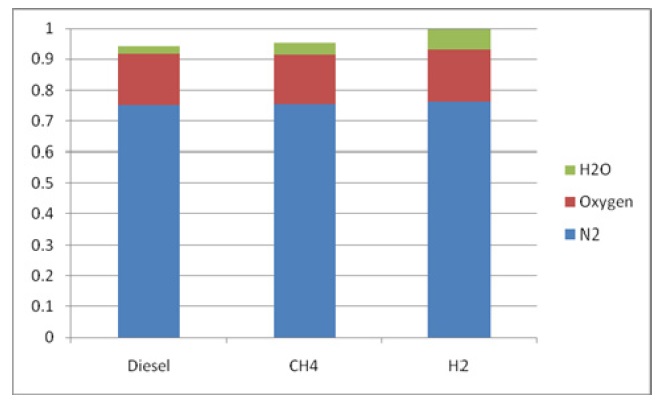
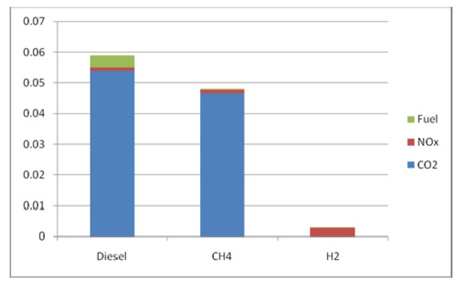
Figs. 11 and 12 show the composition of the combustion products for each case. One of the most important benefits of using hydrogen is the zero CO2 emission levels. It can be observed the high NOx percentage for the hydrogen case.
[Table 2] Comparison of EES and CFD combustor exit temperatures.

Comparison of EES and CFD combustor exit temperatures.
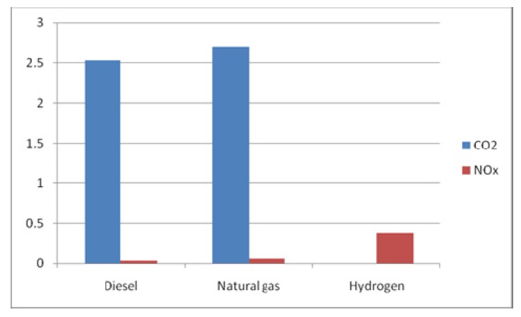
Due to the variable outflow in each of the three cases, the percentage based comparison may be misleading, so the next Fig. 13 quantify the amount of pollutants associated with each case.
When compared to the amount of fuel used (Fig. 13), the NOx rate for the hydrogen case is very dangerous and requires careful measures to be taken to reduce it; these measures include combustion chamber modifications as stated before, as well as post combustion measures like catalytic reduction techniques.
CONCLUSION AND RECOMMENDATIONS
The application of natural gas instead of diesel can be easily adopted without almost any variations or modifications to the design or operation of gas turbine combustors. Natural gas also has many benefits; cleaner combustion achieved by the lower carbon dioxide emission rate and lower un-burnt hydrocarbons. Regarding the nitrogen oxides in the case of natural gas, it is a little higher than the diesel case due to higher combustion temperatures, but lean combustion techniques may be successfully adopted to reduce the maximum temperature and thus the NOx emission rate.
For the case of hydrogen, the studied model showed that many modifications need to be made before using it instead of diesel; higher combustion speed and temperature require alterations to the air distribution inside the combustion chamber to prevent both efficiency reduction and high NOx rates. Due to the elevated nitrogen oxides rates, it may be necessary to use post combustion NOx reduction methods in conjunction with dry low NOx combustion chambers or other methods including more lean air fuel ratio; in this case shorter combustion chambers will be required to prevent excessive flame dilution, this option is very beneficial regarding the weight and volume of the entire engine.
The recommendations for a better future of the marine power plants can be concluded:
Increase the interest of ship owners and designers in the gas turbine market especially for the small and medium sized vessels where high shaft speeds will not require large reduction ratios.
Promote the use of natural gas in the marine transportation sector to have a better environment until the hydrogen is ready to be used on a large basis.
New research programs are needed to find efficient solutions for the problems associated with the application of hydrogen in marine power plants, either in internal combustion engines or in gas turbines.


![Amount of pollutant per fuel unit mass [kg/kg fuel].](http://oak.go.kr/repository/journal/12961/E1JSE6_2013_v5n4_559_f013.jpg)