Compactness and low costs of ICs require a small structure with a thinner lead frame and higher electric circuit integration,which leads to an increase in electric resistance. The heat generation by the resistance in the small structure may cause a decrease in the performance of the ICs or cause a malfunction in the device at constant voltage. On the thermal issue of ICs an experimental approach to facedown or encapsulated thermal chips has been suggested with a simplified analysis of the temperature distribution of the ICs [1]. Also a simplified model was used in the analysis of heat transfer in semiconductor ICs [2].
An automotive IC voltage regulator (AICVR) controls the DC voltage generated by the alternator at the appropriate level (14 V). It consists of one-chip based on a metal-oxide semiconductor field effect transistor (MOSFET) in a small size block, which is subject to Joule self heating during operation. Also as an AICVR is mounted on the alternator in the engine bay it is easily influenced by heat from engine and hood in summer. Recently, according to the requirement of a higher voltage to the alternator brought about by an increase of power consumption by electrical control components in automotive vehicles, the temperature surrounding of the MOSFET in an AICVR becomes increased,making the performance of the MOSFET worse and leading to increased malfunctioning. Several studies have been performed,principally with silicon-on-insulator (SOI) technology which is used for MOSFETs in high temperature fields. Also the inner structure of the SOI was modeled by means of thermal analysis in order to achieve devices which can withstand higher temperatures[3-7]. Although the heat generation occurs in SOIs, the heat transfer depends on the external structure, i.e. it depends mainly on the lead frame or contact area to the substrate and base plate. Composite insulating layers (epoxy, SiO2 wire, Al2O3powder) were compared with each other in respect of heat transfer performance [8]. Six transistors with similar structures were operated under the conditions existing in hybrid electric vehicle(HEV) including high temperatures. They were evaluated in terms of the device failure temperature measured through with the leakage current on an HEV [9]. The outermost cover of the pad-mounted chip, the heat resistant plastic case protects MOSFET from high humidity, heat and physical or electrical impact.However, the limitations of their thermo-physical properties,such as low thermal conductivity and thermal expansion shorten the life of MOSFET packages [10]. The increased requirement for electrical control and associated power consumption in automotive vehicles requires more reliable and stable AICVRs but as already mentioned these increased functions tend to increase the surrounding temperature
In this work, we investigated experimentally the influence of the packaging on the temperature of MOSFET layers under the conditions of high surrounding temperatures.
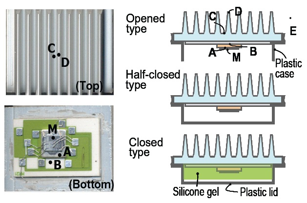
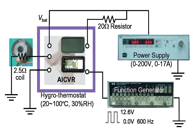
Figure 1 shows a one-chip packaging AICVR without plastic cover. It forms a flat pyramid and is an integrated orderly MOSFET,consisting of a copper heat sink, ceramic substrate of Al2O3 and aluminum base plate with fin. There is soldering between MOSFET and copper heat sink, and between the copper heat sink and ceramic substrate, respectively. The adhesion of the ceramic substrate to the base plate is performed with silicone composite.The AICVR is mainly covered with a plastic case and base plate for cooling. In this work, three types of packaging are used.The first type is filled with thermal silicone gel and covered with a plastic lid on a MOSFET (closed type). The silicone gel is positioned just inside of the outermost packaging, the plastic lid. The second type is covered with a plastic case but without any thermal silicone gel on the MOSFET (half-closed type). In the third type of package there is no lid or thermal silicone gel (open type),so there is direct convective heat transfer from the surfaces of the MOSFET, heat sink and Al2O3 substrate to the surroundings.As the MOSFET is mounted on the face-down substrate in the AICVR, the base plate with an aluminum fin is the top side for all three types. Table 1 shows the thermo-physical properties of the layer of MOSFET and the cover. For each type of test device, the temperature is measured and recorded to a thermal recorder(Yokogawa LR8100; Yokogawa Electric Co., Tokyo, Japan) with a K-type thermocouple (Φ0.13 mm) attached to seven points from the point A to E and M as shown in Fig. 1. Figure 2 electric circuit of the AICVR operating with control devices. The actual operating mode of the AICVR is performed with the circuit which consists of a power supply (HP6030A, 1,000 W, Agilent Technologies Inc., CA, USA), function generator (HP8116A, 0-50 Hz, Agilent Technologies Inc., CA, USA), and resistor (2.5 Ω). In order to satisfy the thermal conditions in the engine bay, the surrounding temperature of the AICVR is established to be 30 and 100°C by the hygro-thermostat (ESPEC corp.; PR-4 KP, Osaka,Japan). The humidity in the hygro-thermostat is maintained to 20%RH during the experiments.
Heat is generated on assigning a voltage of 12.6 V to the AICVR.When the power is supplied to MOSFET, the heat generation is expressed by Eq. (1)

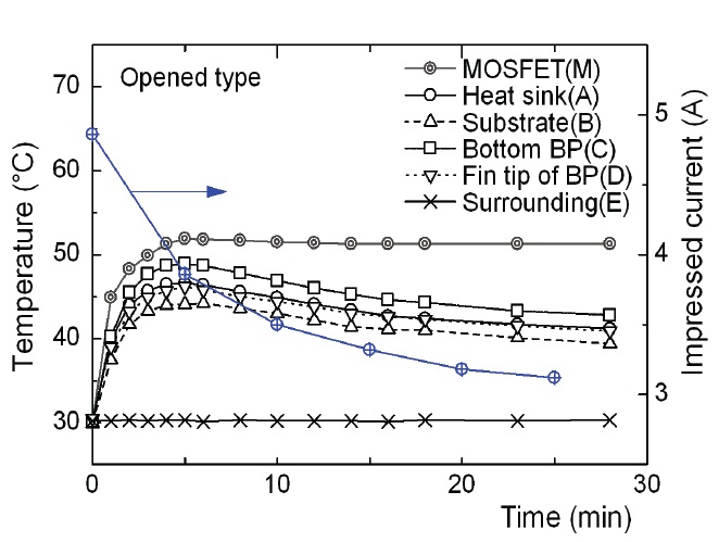
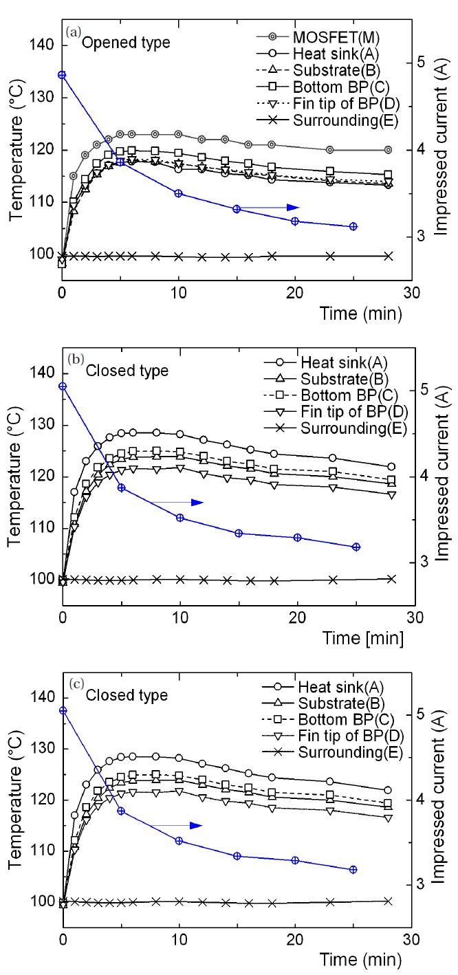
where ID is the drain current(A) and RDS, the resistance from the drain to the source, is 150 mΩ. In the experiments, the measured drain current was 5 A and the heat generation was 3.75 W. Figure 3 shows the time history of the temperature at each point in the open type AICVR when the surrounding temperature is 30℃.
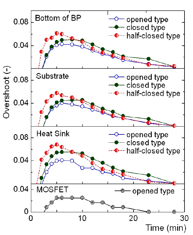
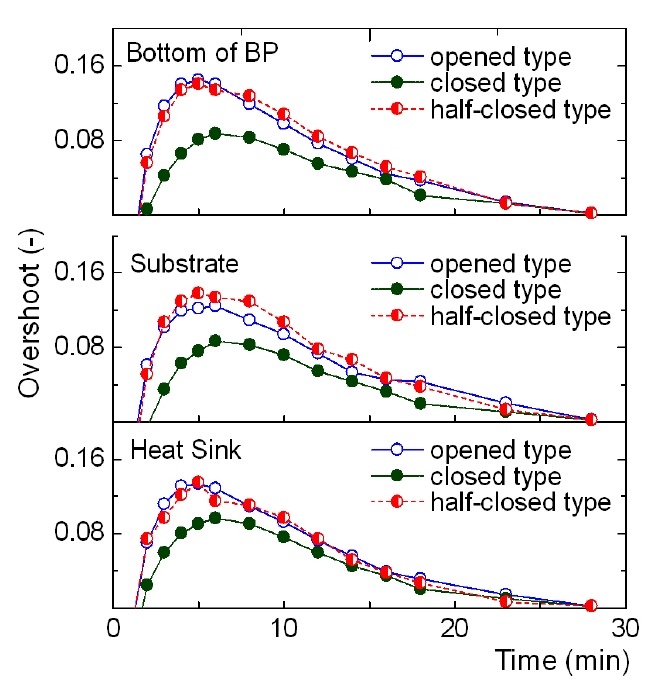
All the temperatures on the MOSFET increased transiently to a maximum, then decreased slowly and were maintained constant after 25 minutes even though the point M shows a very weak pattern.The surface temperature of the heat sink is lower than the temperature at the bottom of the base plate and is near to the Al2O3 substrate surface because the high thermal conductivity of the heat sink makes more rapid the heat transfer to the surrounding than to the other layers. This results in the temperature at the heat sink surface being lower than it is at the substrate surface or at the bottom in the base plate. Also the temperature of the MOSFET increased to a steady 52°C. Furthermore, the current output decreases as the temperature increases from the surrounding level. Figure 4 shows the time history of the temperature at each point on the open type AICVR when the surrounding temperature is 100°C. The trend of the temperature variation of Fig. 4(a) is similar to that of Fig. 3 even though the increase of temperature is about 70°C. Figures 4(b) and (c), however, show a temperature variation that is different from Fig. 4(a), when MOSFET is encapsulated in a plastic package. The temperature of the heat sink is higher than that of the bottom of the base plate because the thermal resistances of the air and plastic lid the behind of MOSFET are larger than those of heat sink, substrate and base plate. The maximum temperature of the heat sink in each graph corresponds to the maximum one for the MOSFET and occurs after about 5 to 8 minutes from when the power is switched on. A temperature of 140°C is known to be the upper limit that can be withstood by a MOSFET. Although the result is satisfactorily in the safe region, the sharp and transient increase of temperature is a threat to the life cycle of the MOSFET when it becomes subject to more severe thermal conditions. In order to investigate the transient response of the temperature, the overshoot is defined by Eq. (2)
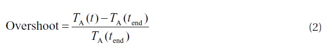
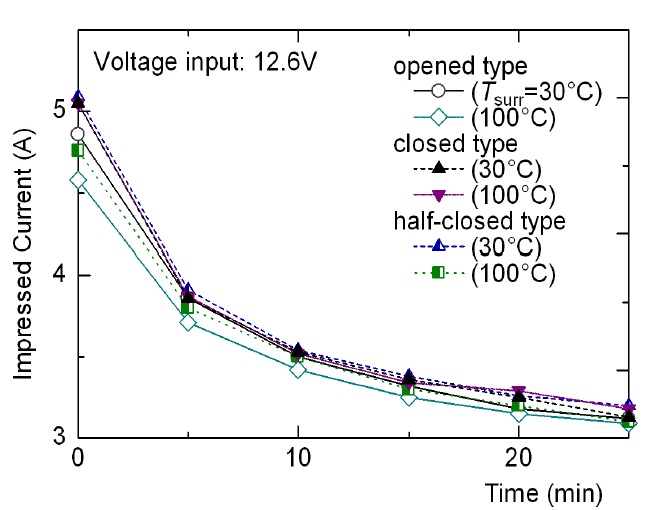
where TA(t) is the temperature at position A at the time t and tend indicates the end time. Figure 5 shows the overshoot of the temperature of MOSFET, heat sink surface, substrate surface and the bottom of base plate with each package type when Tsurr = 100℃.It is noticeable that the overshoot is maximum in the half-closed type of package i.e. the package with no silicone gel on the MOSFET.Here the closed air layer and plastic lid over the MOSFET act as strong thermal insulators. In contrast the overshoot in the closed type is smaller than that in the half-closed one. Therefore it is probable that the silicone gel acts like a heat sink. Furthermore,the overshoot in the open type package is the smallest of all. This result can be explained as follows: The heat generated by the MOSFET in an open package is transferred to both faces of the package, i.e. to both the heat sink and the MOSFET surface open to the air and around which air can flow. Figure 6 shows the overshoot of the temperature to each measuring point when Tsurr= 30℃. The magnitude of overshoot in the opened type increases and then decreases in the closed type, in comparison with the result of Fig. 5. This behavior occurs for two reasons. The first is the decrease in the temperature of the surroundings from 100 to 30℃ and the second is the existence of silicone gel which acts like a heat sink during heat generation. Figure 7 shows the impressed current variation with a voltage input of 12.6 V during the operation of an AICVR. All the patterns in the impressed current are shown to be decreasing exponential functions. Even though the surrounding temperature varies from 30 and 100℃,similar patterns occur in the closed type of packaging also, the extent of the decrease in impressed current is a maximum with the closed type of package, with a surrounding temperature of 100℃, even though the overshoot is not the maximum. It is another issue to elucidate the relation between the packaging structure and the overshoot over the surrounding temperature.
The influence of the packaging state to the temperature variation of a MOSFET layer was investigated on an operational AICVR. All the temperatures at all measurement points showed transient patterns, overshoots and a descending exponential pattern in the impressed current during MOSFET operation. The overshoot of the maximum temperature was most significant with the half-closed type of packaging. The overshoot of the closed type (i.e. near actual condition) of packaging was lower than that for the half-closed one (Tsurr = 100℃) and of the opened one (Tsurr = 30℃). Also the magnitude of the overshoot is dependent on the packaging type and the surrounding temperature.Furthermore the silicone gel plays the role of a heat sink. So apart from its intended purpose of protecting a MOSFET from adverse electrical and mechanical impact, the silicone gel also provides some thermal protection.