Recently, energy saving in public facilities has become very important. Most of public electrical power consumption is expended on lighting for drivers or pedestrians on the road during night time. It is most important that drivers recognize objects on the road during night time for the prevention of traffic accidents.However vehicle head lamps by themselves often provide insufficient luminance. So in many of countries standard guides have been set for road light luminance. Therefore, it is not always true that brighter light produces safer road conditions. It is more important that the road light be well tuned for drivers and pedestrians.i.e. the light can be made more comfortable for their eyes. It is also important to achieve this result with minimum power consumption. Much road lighting is tuned for high power consumption because it has been seriously misunderstood that brighter road lighting means safer road conditions. Also the search for brighter road lighting has been focused on the development of high power consumption lamps and the required circuit systems. However it is more important that lamp reflector design is optimized to reduce power consumption and at the same time provided proper luminance conditions on the road.
We have investigated an optimized lamp reflector design using a ray-tracing method [1]. The design results in definite energy saving effects such as 250 W ceramic discharge metal (CDM) lamp is capable of replacing a 400 W sodium lamp. The standard half-bowl shaped reflector design has been improved. Also the curves of luminance at a 180 degrees viewing angle are presented together with a realistic simulation of luminance on a road.
Finally the lighting conditions on a road have been calculated including the uniformity of lighting. The calculations calculated road condition and uniformity of road that by using an optimized reflector, road brightness uniformity is improved [2-4]. We considered a set the several road lights, and then investigated the continuous road brightness uniformity conditions [2,5-7].
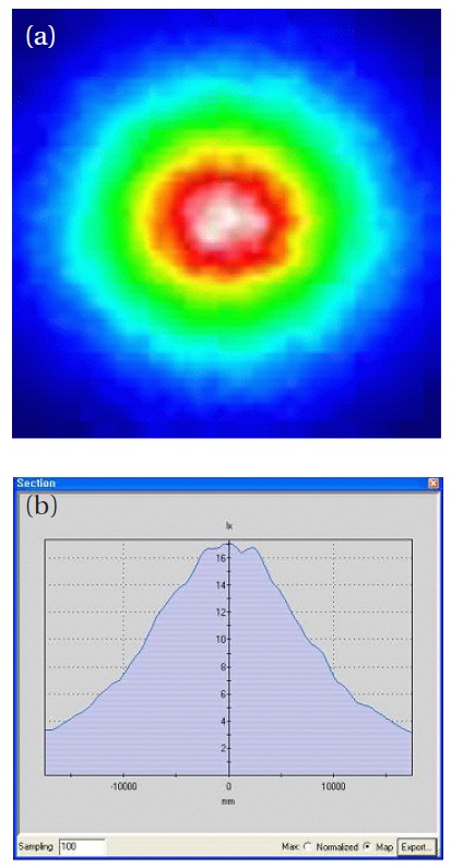
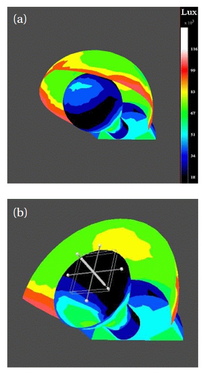
Using the ray-tracing method, we designed a conventional half-bowl shaped lamp reflector and calculated the brightness characteristics on the road. Figure 1 shows a traditional reflector design such as bowl shaped basic reflector of road light. Figure 1 shows the role of reflection on the reflector parts, and Figure 2(a) shows that the brightness on the right bottom part of the designed road light. Figure 2(b) shows the horizontal brightness curve on the illuminated road. It is clearly recognized from Fig.2(b), that the luminance of the central point is 17 Lux and the average brightness was 6.7 Lux. Based on Fig. 1 the most serious defect is the edge part of the opening side. This part (displayed in red) produces many reflections from the CDM lamp.
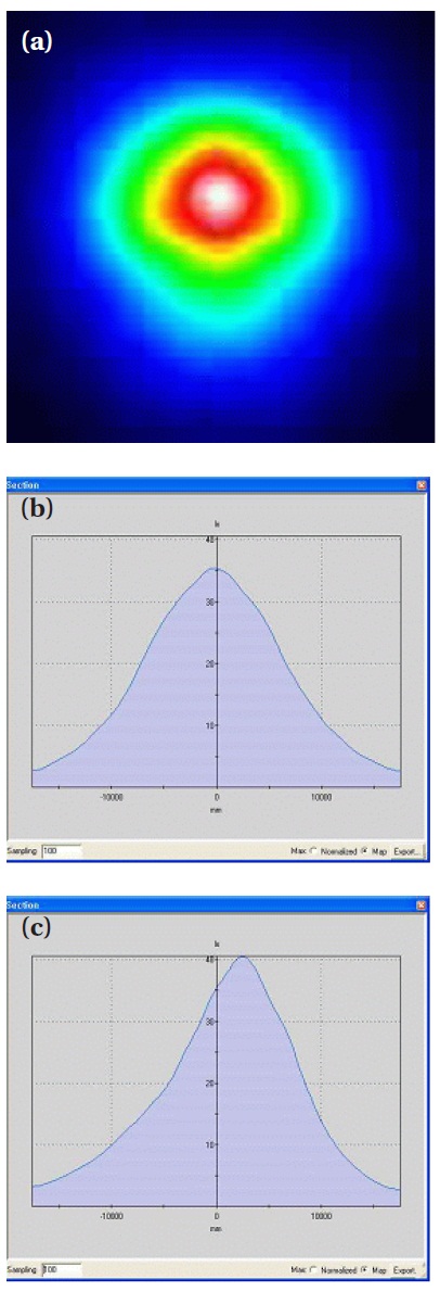
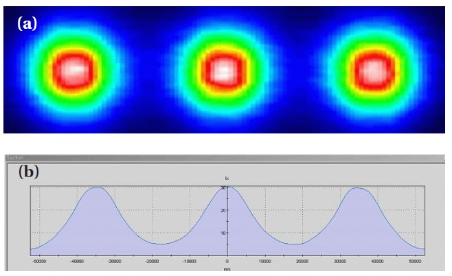
We have improved the above design in the edge parts by the introduction of a cone shaped edge which is good for directing light to the road surface. Figure 3 shows the improved design.Figure 4 shows its improved brightness characteristics on the road surface. In this optimized design the central luminance was 40 Lux and the average brightness was 8.7 Lux. This result shows that improvement of lamp reflector is the major factor in road light design.
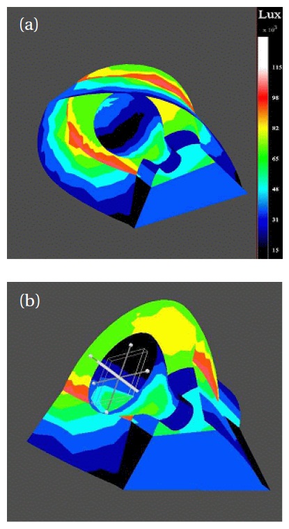
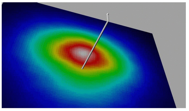
Finally, we have investigated an actual installation simulation.Figure 5 shows the brightness characteristics on the road surface.The road light was set to a height of 12 meter and with a 2 meter distance from the pole to the light. Also the road surface area was set at 35 meter × 35 meter. Figure 6 shows the brightness uniformity of the road surface at several road lamps installed at 35 meter intervals. We studied the improved road light design using the ray-tracing method. First, we presented the improved lamp reflector shape design, particularly improvements in the edge shape of the reflector. It produced significant improvements such as a central brightness of 40 Lux in the traditional half-bowl shape reflector. At the same time the average brightness was improved.Finally we presented a simulation result of actual road lighting conditions and reviewed the uniformity of several road lights under installed conditions.
As a result, using optical simulation such as a ray-tracing method is a very significant method of road light reflector design.The method can achieve a high efficiency reflector design which both reduces power consumption whilst improving the amount and uniformity of the luminance on a road. So, optimized road light design is a necessary element of energy saving and improvement of the road environment at night time.