1. SiC CLADDING AS A REPLACEMENT FOR THE CURRENT ZIRCALOY CLADDING
Zircaloy cladding prevents fission-products’ release into the coolant while imposing major limits on nuclear reactor designs, and safety. These limits are mainly due to zirconium based alloy embrittlement through chemical and radiation damage, early pellet-cladding mechanical interaction (PCMI), and restricted mechanical performance and chemical stability at high temperature. Today, there is a demand for higher burn-up and enhanced safety for light water reactors. Therefore, the limitations of zirconium based alloy cladding are being viewed more critically given recent events. Hence, Light Water Reactor (LWR) performance and safety would be considerably improved by finding a replacement for its cladding that demonstrates better ability to withstand the more challenging LWR conditions [1].
A cladding made of silicon carbide (SiC) has been proposed as a replacement for the current cladding, made of zirconium (Zr) based alloys. SiC is already widely used in many applications involving harsh environments, such as combustion engines. It is also attractive for nuclear reactor applications, especially as a cladding material. SiC captures less neutrons than Zr, demonstrates higher strength at high temperatures, has good chemical stability, and resistance to radiation damage. In short, many of the SiC properties fit well with cladding requirements. However, SiC is a SiC is a brittle material brittle material and has a lower thermal conductivity than zirconium based alloy, thus its introduction into reactors should be subjected to careful evaluation. As such, feasibility of a fuel rod with SiC cladding in LWRs should be subjected to a high level of scrutiny to ensure improved performance in operation and under accident conditions [1].
2. CURRENT STATUS OF SIC CLADDING RESEARCH AND TECHNICAL ISSUES OF SiC CLADDING FAILURE
A fuel rod cladding made of silicon carbide has been studied as a replacement for the current zircaloy cladding in several places around the world [1-9]. Manufacturing SiC cladding made of triple SiC layers - monolith/fiber composite/and environmental barrier coating (EBC) has been developed to dimensions approaching the current LWR fuel rod design [5,7,8]. Radiation performance of SiC/SiC ceramic matrix composite (CMC) cladding has been proven to be promising but heavily dependent upon manufacturing processes [2,10]. Efforts have been made to evaluate SiC oxidation performance under Loss of Coolant Accidents (LOCAs) during its service as LWR cladding [1,6,7,11]. These SiC oxidation studies have demonstrated orders of magnitudes slower reaction rate than that of Zr. This is an indicator that major failure modes for SiC cladding would be principally different from failure modes of the Zr cladding stated in the U.S Code of Federal Regulation, Title 10, Part 50.46, “Acceptance Criteria for Emergency Core Cooling Systems (ECCS) for Light-Water Nuclear Power Reactors” (10 CFR 50.46) [1,12,13]: 10 CFR 50.46 states:
1. Peak cladding temperature. The calculated maximum fuel element cladding temperature shall not exceed (1204℃).
2. Maximum cladding oxidation. The calculated total oxidation of the cladding shall nowhere exceed 0.17 times the total cladding thickness before oxidation (Equivalent Cladding Reacted, ECR).
3. Maximum hydrogen generation. The calculated total amount of hydrogen generated from the chemical reaction of the cladding with water or steam shall not exceed 0.01 times the hypothetical amount that would be generated if all the metal in the cladding cylinders surrounding the fuel, excluding the cladding surrounding the plenum volume, were to react.
4. Coolable geometry. Calculated changes in core geometry shall be such that the core remains amenable to cooling.
5. Long-term cooling. After any calculated successful initial operation of the emergency core cooling system (ECCS), the calculated core temperature shall be maintained at an acceptably low value and decay heat shall be removed for the extended period of time required by the long-lived radioactivity remaining in the core.
It is worth noting how pervasive the effects of cladding oxidation are in the establishment of the current U.S NRC LOCA criteria. Indeed, the fundamental mechanism of cladding embrittlement of zircaloy during LOCA is due to micro-structural changes of the cladding with oxidation [14,15]. That is, the oxidized cladding cross section exhibits an oxide layer, an oxygen stabilized alpha-phase layer, and a region of prior beta-phase. Importantly, oxidation of zircaloy above the alpha-to-beta transformation temperature results in inherently brittle phases for the regions affected by oxygen. Hence, ductility of zircaloy cladding is significantly impaired with oxidation, and embrittlement can lead to cladding fragmentation during the quenching phase in a LOCA. The ability of the cladding to withstand the thermal shock stresses during the reflood phase of LOCA is closely related to the degree of oxidation reaction [13,16]. The current allowable peak cladding temperature (1204℃) and the maximum oxidation (17% ECR) criteria were chosen in such a context ? these limits are adequate to ensure the survival of the cladding under the thermal shock during the reflood phase of LOCA. The maximum hydrogen generation limit is also affected by cladding oxidation. In addition, the coolable geometry criterion concerns the change in coolant channel geometry due to potential blockages through brittle cladding failure. The cladding brittle failure is predominantly caused by lower ductility as a result of oxidation during LOCA. The Long-term cooling criterion is also affected by cladding oxidation, as the oxide layer formed on the cladding surface lowers the cladding thermal conductance. Today, the U.S NRC is modifying 10 CFR 50.46 to reflect the fact that the current limits of maximum cladding temperature and maximum oxidation are not conservative for high burnup cladding [17,18]. In particular, hydrogen embrittlement of zircaloy is significantly exacerbated with burnup. The new rule is focusing on maintaining appropriate ductility as the unit of measure to determine survivability during the quench process and any other unforeseeable event.
Hence, research conducted prior to this point assures that failure mechanisms, hence safety criteria, of SiC cladding would principally depart from the current practice established based on Zr based cladding. Indeed, the attempt to use SiC definitely is a radical departure from the present experience, with different material (ceramic) from stainless steel and metal based alloys. At this early stage of our assessment of SiC cladding behavior in LWRs, the focus should be on understanding failure modes because they will reveal the feasibility, performance, and appropriate design and safety criteria [1].
A key failure mode of SiC cladding can be expected to arise from its brittleness, when fast fracture occurs under excessive tensile stresses. In this study, thermal stresses caused by rewetting of fuel rods during the reflood phase of a LOCA are investigated as a probable mode for excessive tensile stresses in fuel rod cladding.
3. BACKGROUND ON SiC CLADDING THERMAL SHOCK FRACTURE
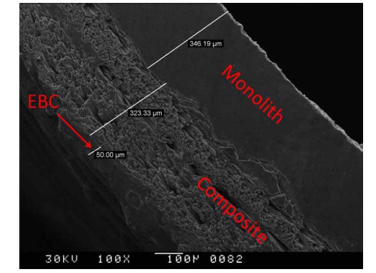
Failures of a load bearing structure can be either of the yielding-dominant or fracture-dominant (fast fracture) types. Fast-fracture dominant failures are fractures that occur before general yielding. For such failures, the size scale of defects, which is of major significance, is essentially macroscopic, since general plasticity is not involved but only highly localized plasticity is involved with flaws or defects [19]. Fast fracture of ceramics due to lack of ductility to accommodate defects undergoing plastic deformation has been a relatively well understood subject. Monolithic SiC undergoes a fast fracture failure mode if tensile stresses are excessive [20,21]. SiC/SiC composites exhibit rather complex modes of failures that show some degree of ductility [23,24], which is sometimes called brittle-like (or quasi-ductile) failure. For the SiC cladding design for LWR application, the CMC design is being considered [1,2,7]. The CMC design employs monolith SiC as the inner most layer of the cladding, mainly to keep the fission gas inside the rod, and provide strength to the cladding. The outer monolith layer protects against the corrosive action of water, while the middle SiC/SiC composite, characterized by a higher fracture toughness than the monolith, is used to protect the inner monolith and to make the cladding failure happen in a less drastic manner. A thin CVD prepared environment barrier coating (EBC) is employed at the outer most protective layer. Figure.1 illustrates a typical design for CMC layers.
Under accident conditions, fuel cladding may experience significant tensile stresses due to both thermal shock, and rapid depressurization of the core operating pressure. For ceramics, cracks in compression tend to get closed up and propagate stably, and may twist out of their original orientation to propagate parallel to the compression axis [25,26]. Fractures are not caused by rapid unstable propagation of one crack, but by the slow growth of many cracks to form a crushed zone. It is not the size of the largest crack that counts but that of the average crack size [25]. In contrast, cracks in tension tend to open and propagate unstably perpendicular to the applied stress direction. In such a case it is often the largest crack that governs failure. Hence, the projection of stress distributions around flaw locations inside the cladding should be determined to analyze thermal shock performance.
A triplex cladding is regarded as a more robust structure for thermal stresses induced by quenching than the cladding structure made of a sole monolith; the CMC structure has a composite layer of high fracture toughness with additional crack arresting capabilities. The outer most layer of the cladding experiences the greatest tensile stress as it sees the sharpest temperature gradient in reflood cases of LOCA. EBC is a monolithic SiC, which exhibits lower fracture toughness compared to composite materials. In case of the failure of EBC upon quenching, propagating cracks would run into the neighboring composite layer, which is unfavorable for crack growth. Hence, understanding of the CMC fracture upon quenching requires a detailed
description of stress fields in each layer, flaw distributions, and crack propagation mechanisms between the layers. This study explores monolithic SiC performance upon quenching as a preliminary attempt to envision material performance of the EBC layer and the innermost monolith. Thus, it provides a building block for understanding the CMC cladding behavior.
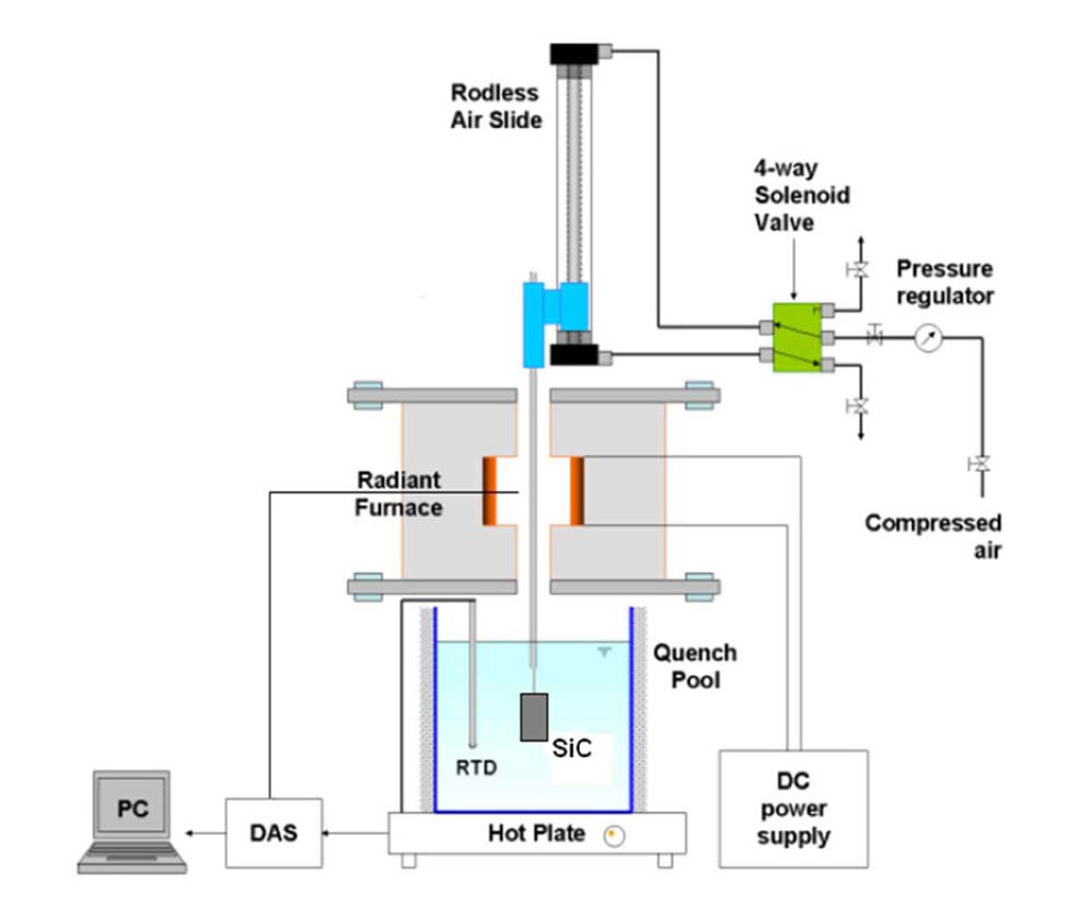
An experiment facility was built to bring SiC specimens up to 1500℃ and drop them into a pool of water, as illustrated in Fig.2. The tubular SiC specimens are suspended in the air inside a quartz tube located at the center of the furnace. By employing bottom-flooding with tubular samples, this experiment was designed to demonstrate similar experimental designs/conditions that were used to establish the current Zr cladding safety criteria [13,34] written in 10 CFR 50.46. A B-type thermocouple reads the temperature adjacent to the outer surface of the quartz tube, where the SiC specimen is located. The temperature reading is recorded by the data acquisition system (DAS). Temperature calibrations were made between this B-type thermocouple reading and the temperature obtained by a thermocouple attached to the sample’s surface. Comparing these two temperatures, an empirical relation between the furnace temperature and the true sample surface temperature was established and used to report SiC specimen temperatures. SiC specimens were suspended inside the furnace until it reached constant temperature. Then, specimens were quickly dropped into the room temperature water pool (~22℃) by an air-pressure driven rod. A high speed video camera was used to record the quenching of the specimens. Recorded quenching videos were used to analyze transient boiling states for later application in modeling.
The material used in this experimental study was monolithic tubular Hexoloy α-SiC with a density of 3.05g/cc, obtained from Saint-Gobain. The specimens had dimensions of 14mm OD, a thickness of 1.55mm, and a height of 13mm. The sample was received as a long tube, and was cut into the specimen size. Cut end surfaces were polished by a grinding wheel, and then ultrasonically cleaned with detergent added to water, deionized (DI) water, acetone, and methanol prior to furnace exposures. Postquenching examinations were conducted with scanning electron microscope (SEM) analysis for all tested specimens.
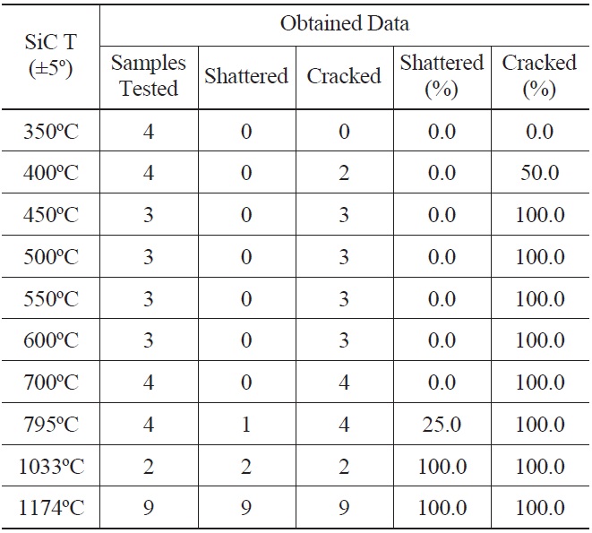
39 SiC specimens at temperatures ranging from 350℃ to 1174℃ were quenched into deionized water at 22℃. A minimum of three independent tests were performed for each temperature, except for 1033℃. Experimental results are summarized in Table 1.
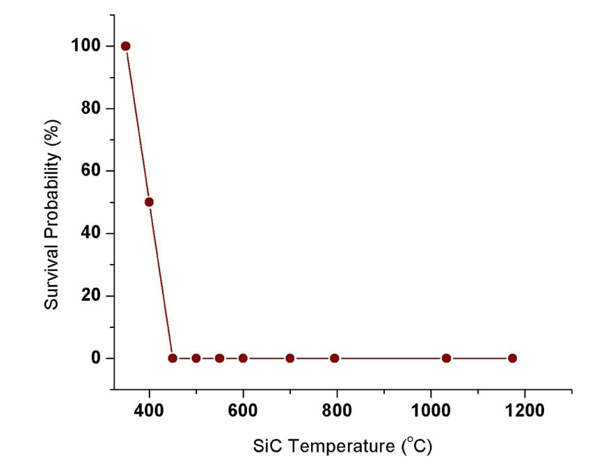
Shattered specimens are ones that immediately broke into multiple pieces upon quenching. Cracked specimens are ones that were observed to have crack growth by either visual examination or SEM analysis. Thus, all shattered specimens are regarded as cracked specimens. The experimental results show that SiC specimen temperatures above 350℃ result in crack formation for the tested temperature resolution. For those crack inducing quenching temperatures, SiC specimens are expected to undergo strength degradation after the thermal shock. Past thermal shock studies conducted with SiC found threshold material temperatures for strength degradation [27]. In this study, we used survival probability as a measure of thermal shock tolerance, which is defined as the ratio of the number of crack-free samples / number
[Table 1.] Thermal Shock Experiment Results

Thermal Shock Experiment Results
of total samples tested after quenching. Visual observations of cracks in SEM analysis are limited to only surface cracks. Hence this may underestimate thermal shock damage on the material. Nevertheless, it can still reveal a strength degradation trend with quenching temperature as shown in Figure.3.
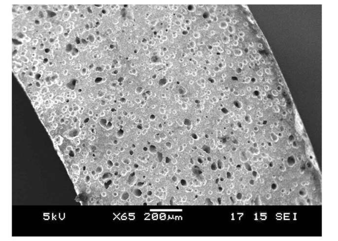
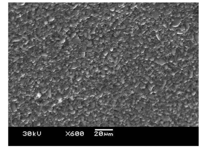
Tested SiC materials are pressureless sintered α-SiC, which is characterized by considerable porosity. Representative SEM images of pre-quenched specimens are shown in Fig. 4 and Fig. 5. Pores can essentially play as a preexisting flaw where stress is concentrated. The SEM analysis in Fig.4 shows average pore diameters 20-50μm that are distributed uniformly. Neither pores nor pre-existing flaws
were observed on the side surface of as-received tubular specimens, Fig. 5.
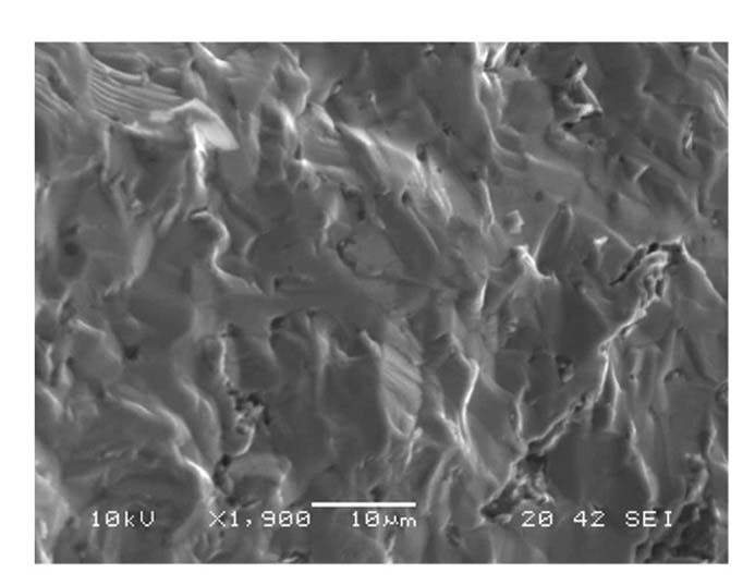
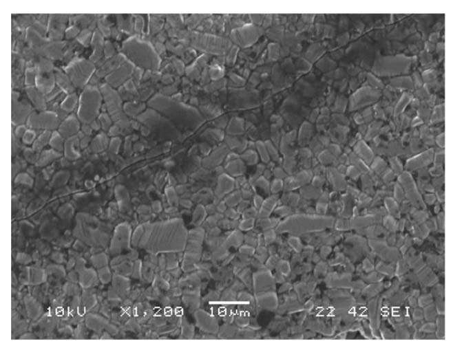
Fractured surfaces of shattered samples showed that cracks propagate through grains (transgranular fracture), Fig.6. Transgranular crack propagation was commonly observed for all cracked samples at lower temperatures as illustrated in Fig. 7. Transgranular fractures explain fairly straight looking cracks with smooth edges, which are different from the faceted fracture surfaces resulting from intergranular fractures. To enhance fracture toughness, intergranular rather than transgranular fractures need to be promotednular fracture cracks take a straight path through grains, whereas intergranular cracks do not enter grains, instead traveling along the grain boundaries. This allows the branching of the crack through interlocking grains, enhancing overall toughness [28].
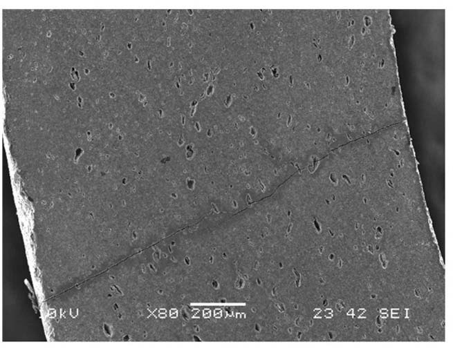
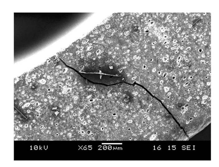
Once formed, cracks tend to run axially and radially across the entire thickness of tubular specimens. This indicates that hoop stress is the most dominant stress direction for crack propagation. Crack growth exhibited different behavior for different quenching temperatures. Higher quenching temperatures caused a wider crack width as shown in Fig. 8 and Fig. 9.
Cracks that were formed at 1174℃ are about 25 μm wide while those at 450℃ were less than 5 μm. Temperature gradients inside a quenched material are steeper when quenching from higher temperatures due to the initial temperature difference. Steeper temperature gradients lead to a greater thermal expansion mismatch inside a material,
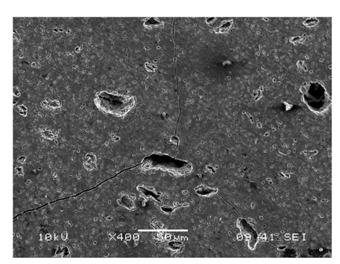
causing higher stress levels. Higher stress levels are energetically more favorable for crack propagation and a material accommodates a higher strain energy release rate by creating larger cracks. Cracks exhibited a tendency to be linked at pores as shown in Fig. 10. This explains that pores (sites of void where no elastic potential energy can be accommodated) are energetically favorable for crack propagation.
6. THERMAL STRESS MODELING OF TRANSIENT LWR FUEL RODS
A rigorous analysis of the observed experimental results would come from understanding the fracture mechanism under certain stress fields. There have been many studies on transient stress field calculations for quenched materials.
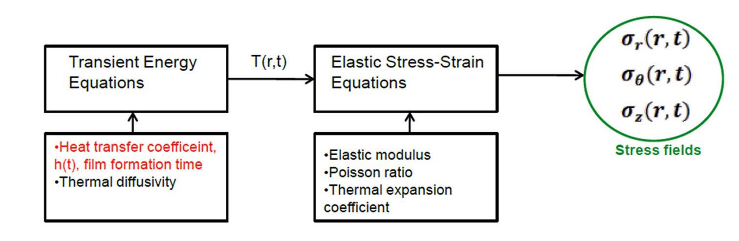
Generally, transient energy equations are solved for a fixed heat transfer coefficient and thermal diffusivity of the material to obtain transient temperature fields. This temperature field is then inputted into elastic stress-strain equations to obtain transient stress fields as illustrated in the schematic diagram in Fig. 11.
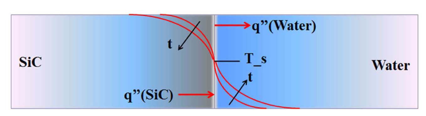
Although the convention of one sided coupling of energy and stress-strain equations is a first principle approach that can be applied universally for various thermal shock cases, care should be taken in using it. Heat transfer modes between a quenched material and coolant should be carefully addressed. Conduction may be the dominant heat transfer mode for the early portion of the transient before any appreciable convective heat transfer mode such as film boiling occurs [29,30]. Maximum stresses may be created during this early portion of the transient. At the instant when a SiC specimen meets quenching water, the instantaneous SiC surface temperature can be found by assuming the situation as a contact of a semi-infinite solid. This approximation is reasonable for the early portion of the transient, during which temperatures in the interior are essentially uninfluenced by the change in surface conditions and conduction is the dominant heat transfer mode [31].
The instantaneous surface temperature, Ts, can be found by the energy balance at the interface [31]
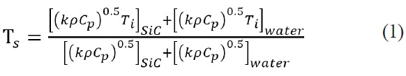
where k is conductivity,
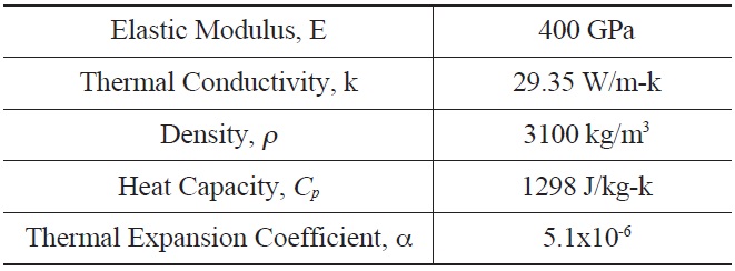
[Table 2.] Input for α-Hexoloy SiC Properties for Thermal Stress Calculation

Input for α-Hexoloy SiC Properties for Thermal Stress Calculation
instant of the early portion of the transient, material temperature distribution T(x, t)SiC can be calculated as follows [31]
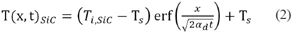
where

where
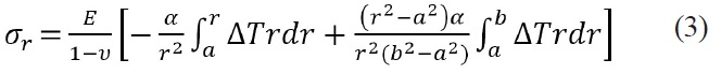
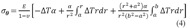
position of the innermost surface, b is the radial position of the outermost surface, and Δ
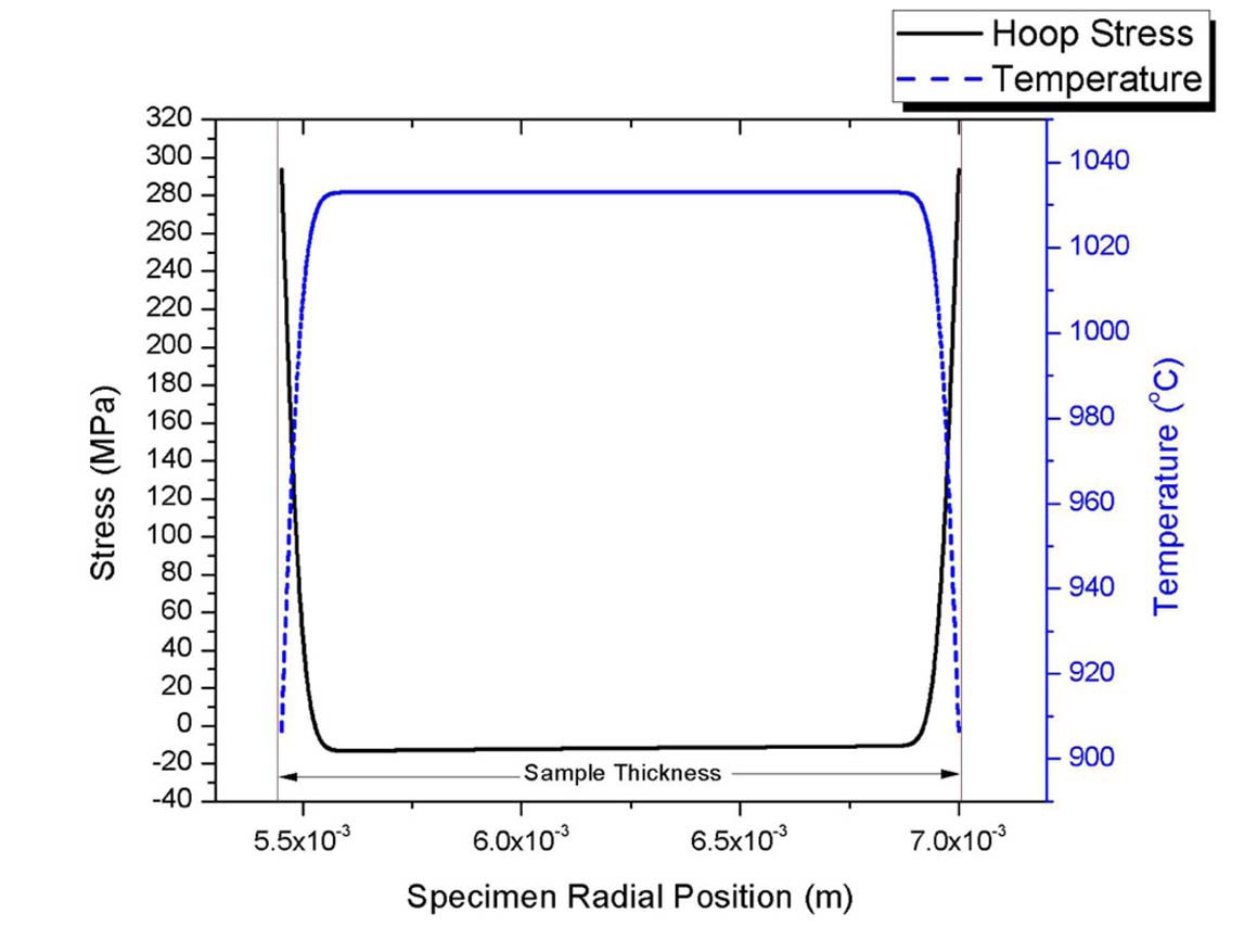
Stresses are tensile at the outer surfaces while compressive in the middle of the quenched specimen as shown in Fig.13. Results shown in Fig.13 exhibit sharp temperature and stress gradients during the earlier portion of the transient while the interior temperatures are unaffected. The stresses are projected over a finite thickness of a critical flaw and increases stress intensity. If thermal stress intensity is larger than the material’s fracture toughness, fractures are initiated Pores were uniformly populated over the entire thickness of the tested specimens. Pores/flaws near the surfaces are more significant in contributing to fracture than internal pores/flaws, which is a primary reason why surface quality control of SiC cladding is important.
Note that the calculated stresses based on the conduction model in the very early portion of a transient are the ceiling for true maximum stresses. They assume water as a neighboring continuum, where heat can flow without an interface thermal resistance. In reality, a heat transfer mechanism would be somewhat mixed between conduction and convection. Thermally induced agitations of water molecules due to rapid heat conduction and water movement next to the sample surface with dropping the specimen would result in a certain macroscopic movement of water molecules. This macroscopic movement of water would provide an additional mechanism for heat transfer. Also, contact resistance in heat transfer would exist between the quenched material and the neighboring water during transient conduction. The lowest limit for the true maximum stress would be the immediate boiling heat transfer at time zero. This would impose thermal resistance at the beginning and neglect the conduction dominant phase of the transient. Thus, the true maximum stresses would be bracketed by these two limiting cases
Even for a convective heat transfer after an appreciable convection starts, the heat transfer coefficient rapidly changes with time depending on the sample temperature. Hence, using a single heat transfer coefficient may lead to an unrealistic interpretation of the experimental results. Consequently, current thermal shock models set a limit on the use of commercially available software for the cladding temperature analysis upon quenching during a reflood phase. Current understanding of transient energy analysis for fuel rods during accident scenarios does not take into account the discussed technical details, because it uses the instant boiling model at time 0.
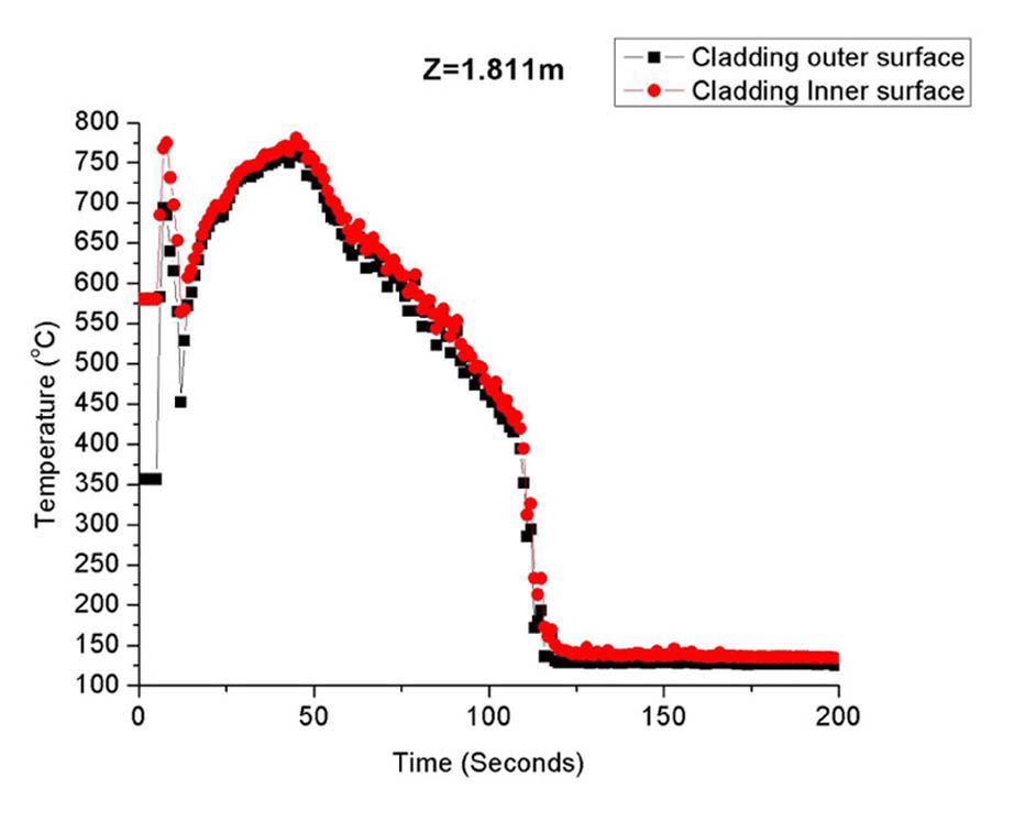
A large break loss of coolant accident (LBLOCA) analysis in a typical PWR was run by RELAP-5 as a test case (input of the U.S. NRC) [32]. Cladding thermal conductivities and heat capacities were modified to SiC properties found in Carpenter’s work [2]. Fig.14 shows peak fuel rod cladding temperature with time at the axial location of 1.811m.
Fuel rewetting starts at 100~125 seconds with the rapid temperature drop. During the rewetting process, thermal stresses induced by the temperature gradient inside the cladding are expected to be small with similar cladding outer and inner surface temperatures. This may be an unrealistic snapshot of cladding temperatures for the very early phase of quenching where the inner most cladding surface is not affected by the outermost temperature perturbation. Such an instant moment would be the time when the cladding experiences the greatest stress. The current RELAP-5 models and numerical schemes are not intended to handle such rapid transient thermal hydraulicstress coupling. The same can be said for the NRC oxide fuel transient analysis code, FRAPTRAN 1.4. Such a rigorous thermal hydraulic-stress coupled model is not required by the current criteria set for the zircaloy cladding. These criteria are indeed empirical judgment supported by many redundant experimental data. Since brittle fracture of zircaloy upon quenching is a conditional failure that takes place after considerable oxidation, rigorous modeling has been made primarily for the modeling of oxidation and hydriding. Quenching performance of zircaloy oxide layer and underlying brittle phase has been predominantly addressed by means of experimentation with qualitative explanation in terms of the degree of oxidation damage and retention of ductility. For SiC cladding, this approach may not be acceptable because brittle fracture upon quenching is not a conditional failure mode. Rigorous investigations of structural failure in terms of imposed excessive stresses should be pursued. Efforts are being made to explain presented experimental results with modeling. Experimental results in Table.1 and survival probability shown in Fig.1 do not necessarily imply the same behavior for CMC cladding. Stress fields that tested specimens are different from the reality of an actual CMC cladding. The main difference comes from (1) two sided quenching for tested specimens while only the outer most surface sees cold water in case of an actual fuel rod, and (2) additional tensile stresses would be imposed for an actual fuel rod due to depressurization of the reactor.
In thermal shock experiments, pressureless sintered α-SiC exhibited vulnerability to transgranular fracture with temperature dependence of survival probability. Pores acted essentially as pre-existing flaws and transgranular cracking with pore bridging was observed. Well prepared CVD β-SiC with minimal porosity is worth testing as a comparison in terms of thermal shock performance. Fracture models being developed for α-SiC can readily be applied to β-SiC with a correction on pre-existing flaw size and geometry. The heat transfer mechanism has a dominant role on temperature gradient inside the material and therefore stress fields. Rigorous treatment of material behavior, such as thermal hydraulic coupling during the early portion of transient is absent in current codes. Through this study, advancements in thermal shock models that are readily applicable to LWR fuel rods of ceramic cladding, including SiC, are being developed.
k ?Thermal Conductivity [W/m-k]
T ?Temperature [℃ or K]
E ?Young’s Modulus [GPa]

![CMC SiC Cladding Layers
(Figure in Courtesy of Stempien.et.al. [10])](http://oak.go.kr/repository/journal/12852/OJRHBJ_2013_v45n6_811_f001.jpg)