The first phase of the pre-conceptual design for the ASTRID1, 2 prototype (Advanced Sodium Technological Reactor for Industrial Demonstration) ended in 2012. This paper assesses the studies carried out to date concerning the core design (at 1500MW) which falls under the responsibility of CEA.
Since 2007, core design efforts were focused on the research of small burn-up reactivity excess and the low sodium void effect. The first studies resulted in a core design called SFR V2b3, with the following specifications: a very low reactivity level (due to a small cycle reactivity loss: -1.10-5Δk/k/efpd) and a reduced sodium void effect (~5$) compared to past designs. These improvements result from an innovative fuel sub-assembly based on a “large pin and small wire” concept.
More recently, studies were carried out on an evolutionary core design named CFV 4, presenting a large gain on the total sodium void effect.
The pre-conceptual design phase 1 focused on the CFV concept, based on the use of a sodium plenum zone, an absorbing zone in upper shielding, and an internal fertile zone in specific core geometry.
A SFR V2 core at 1500MW, derived from the SFR V2b concept, was also designed and CFV cores are compared to this homogeneous reference core.
The first assessments carried out on version v1 of the CFV concept showed a promising safety improvement for this type of concept5. These studies were continued in 2012 with the aim of optimising this concept with respect to the ASTRID safety objectives by investigating the possibility of:
- Increasing the safety margins in relation to the boiling point in the event of a total loss of power to the reactor without scram.
- Increasing margins in relation to fuel meltdown in the event of an accidental control rod withdrawal.
- Increasing margins in relation to the reactivity control requirements.
The options chosen to achieve these goals in version v2 of the CFV core were the following:
Decreasing the fuel temperature at full rated power, which is favourable in the event of a total loss of power to the reactor without scram (reduction of the Doppler integral) while increasing the fusion margin in the event of a control rod withdrawal (increase in the ratio between the linear power to fusion and the initial linear power) obtained by:
- Reducing the linear power by increasing the number of fuel pins per sub-assembly (switching from 217 to 271 pins).
- Reducing the power density by increasing the number
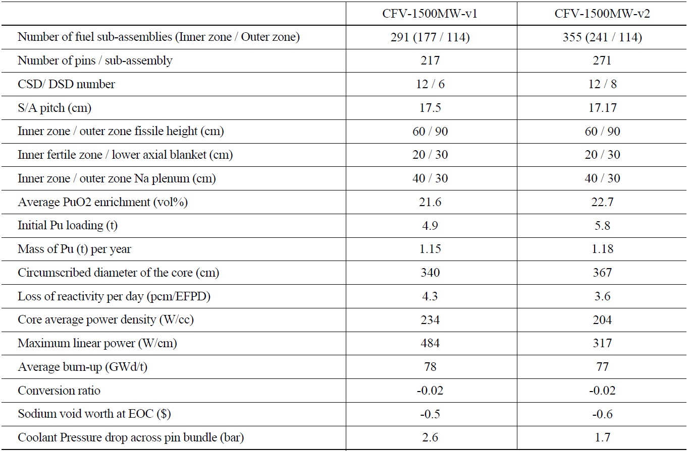
[Table 1.] Summary of the Characteristics of the Cores studied During Pre-conceptual Design Phase 1

Summary of the Characteristics of the Cores studied During Pre-conceptual Design Phase 1
of fuel sub-assemblies (addition of an assembly ring).
Adding shutdown rods to increase the margins between control requirements and available reactivity worth.
In addition, the design was optimised by 1) reducing the duct wall thickness and the inter-assembly gap according to the proposals resulting from the preliminary design studies on the fuel sub-assemblies, 2) using full fertile pellets (increased breeding gain and reduced loss of reactivity), and 3) minimising the quantity of B4C in the upper neutron shielding (while respecting the negative sodium void worth criterion).
The following table summarises the characteristics of versions v1 and v2 of the CFV core.
The CFV cores under study comply with the performance requirements of the ASTRID specifications in terms of fuel residence time, fuel cycle length, average burn-up, and breeding gain.
In terms of the overall dimensions, the CFV v2 core has a circumscribed diameter which is slightly larger than that of the CFV v1. This is due to the design options (strong reduction in the power density and the linear power) which aim at reinforcing the intrinsic safety behaviour.
It was checked that the CFV cores made it possible to achieve the performance levels expected in terms of transmutation for the ranges considered for the ASTRID project (up to 2% of homogeneous americium and 10% for minor-actinide-bearing blankets, known as MABB).
Lastly, the studies conducted on the cores at 3600 MW showed that the performance of the CFV cores could be extrapolated up to this level of power.
3.1 Severe Accident Prevention Situations
As far as severe accident prevention is concerned, the following conditions have been studied:
Unprotected loss of flow (ULOF) sequences:
- Total loss of power without reactor scram resulting in the coast down of the primary and secondary coolant pumps and steam generators dry out. This was the reference sequence in the safety files for previous reactors
- Coast down of all the primary pumps without reactor scram while the secondary coolant pumps remain operational to remove power. This sequence is an alternative to the previous sequence.
- Failure of a pump ? diagrid connection without reactor scram. In this scenario, the behaviour of the core can be assessed with respect to fast flow losses.
A sequence of unprotected loss of heat sinks (ULOHS):
the secondary pumps are tripped and the steam generators dry out without reactor scram.
Conditions involving control rod withdrawal (CRW), with or without detection.
The results and the analysis of two sequences of ULOF and ULOHS are presented hereafter for the CFV cores as well as for a SFR V2 core, for comparison.
Modelling
The accident sequences were simulated with the CATHARE6 code. The core, the entire primary system, the secondary circuit, and the steam generators have been modelled. The water-vapour conversion system is represented by limit conditions at the inlet and outlet of the steam generators.
At the same time as the accident sequence calculations, work also focused on improving the modelling (modelling of the core and fuel pins based on GERMINAL7, 8 calculations, modelling of the secondary circuit, etc.) during the entire pre-conceptual design phase 1, which will be continued during the conceptual design phase.
In particular, following the exchange of information with the manufacturer that conceives the primary pumps, new pump characteristics were taken into account (which are more penalizing for transients than the characteristics considered for the studies presented last year5).
Total loss of power transient
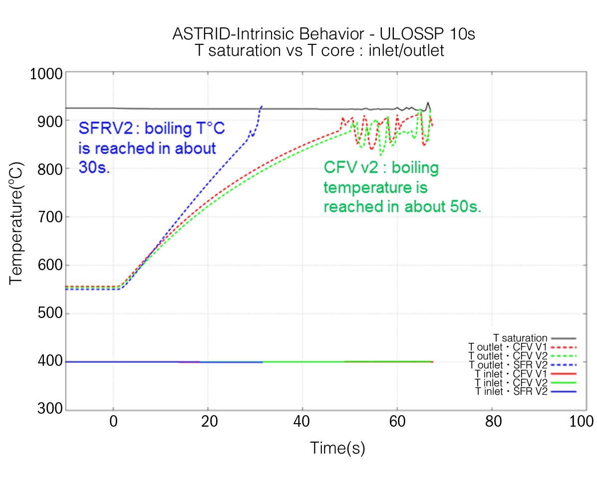
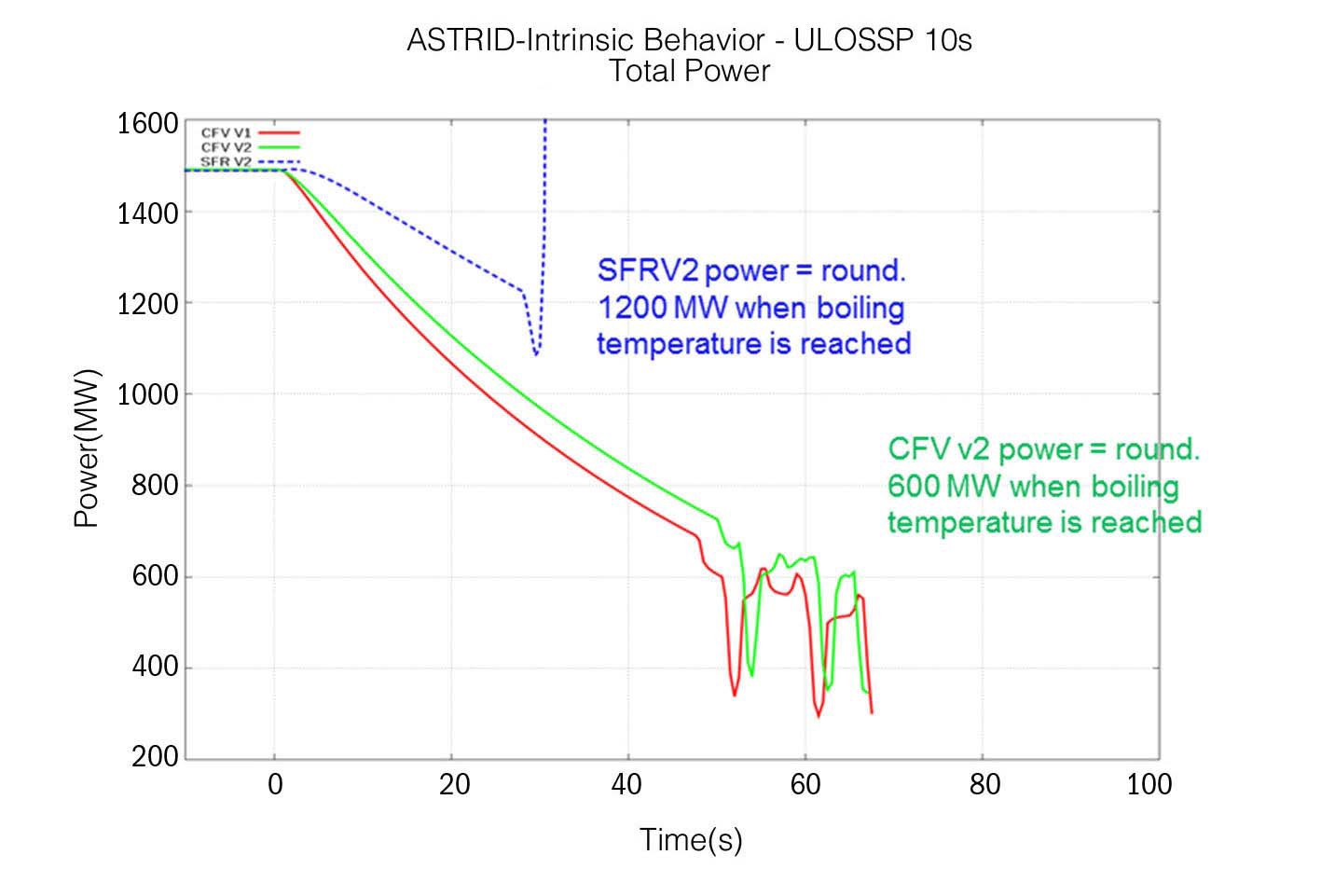
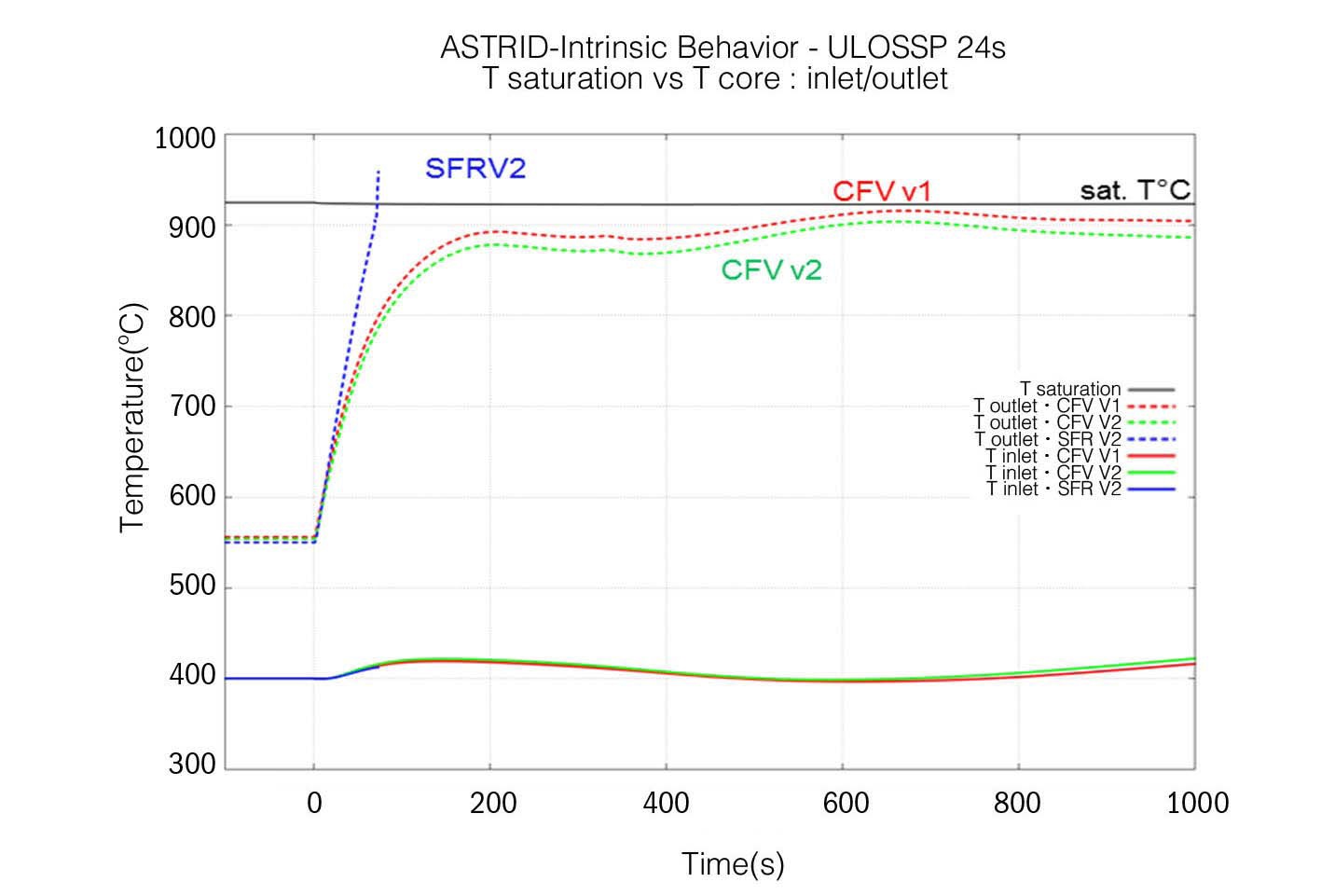
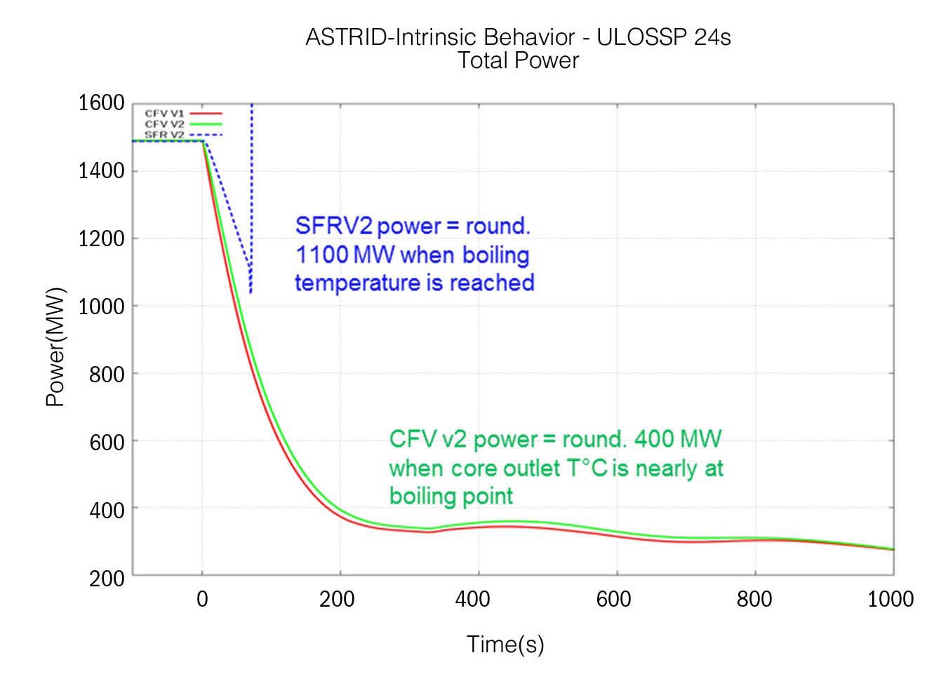
The following graphs represent the variations in the core outlet temperature (maximum temperature at the outlet of the hottest sub-assemblies) and in the core power during a total-loss-of-power transient for a SFRV2 core, as well as for the CFV v1 and CF v2 cores.
Figure 1 and Figure 2 correspond to a calculation in
which the mechanical inertia of the primary pumps generates a semi-flow rate in the core within 10 s.
Figure 3 and Figure 4 correspond to a calculation in which the mechanical inertia of the primary pumps generates a semi-flow rate in the core within 24 s.
The results show that the specific characteristics of the CFV core (in particular, its set of neutron feedback and a low sodium void coefficient) lead to a behaviour scenario with different and more favourable kinetics than for the SFRV2.
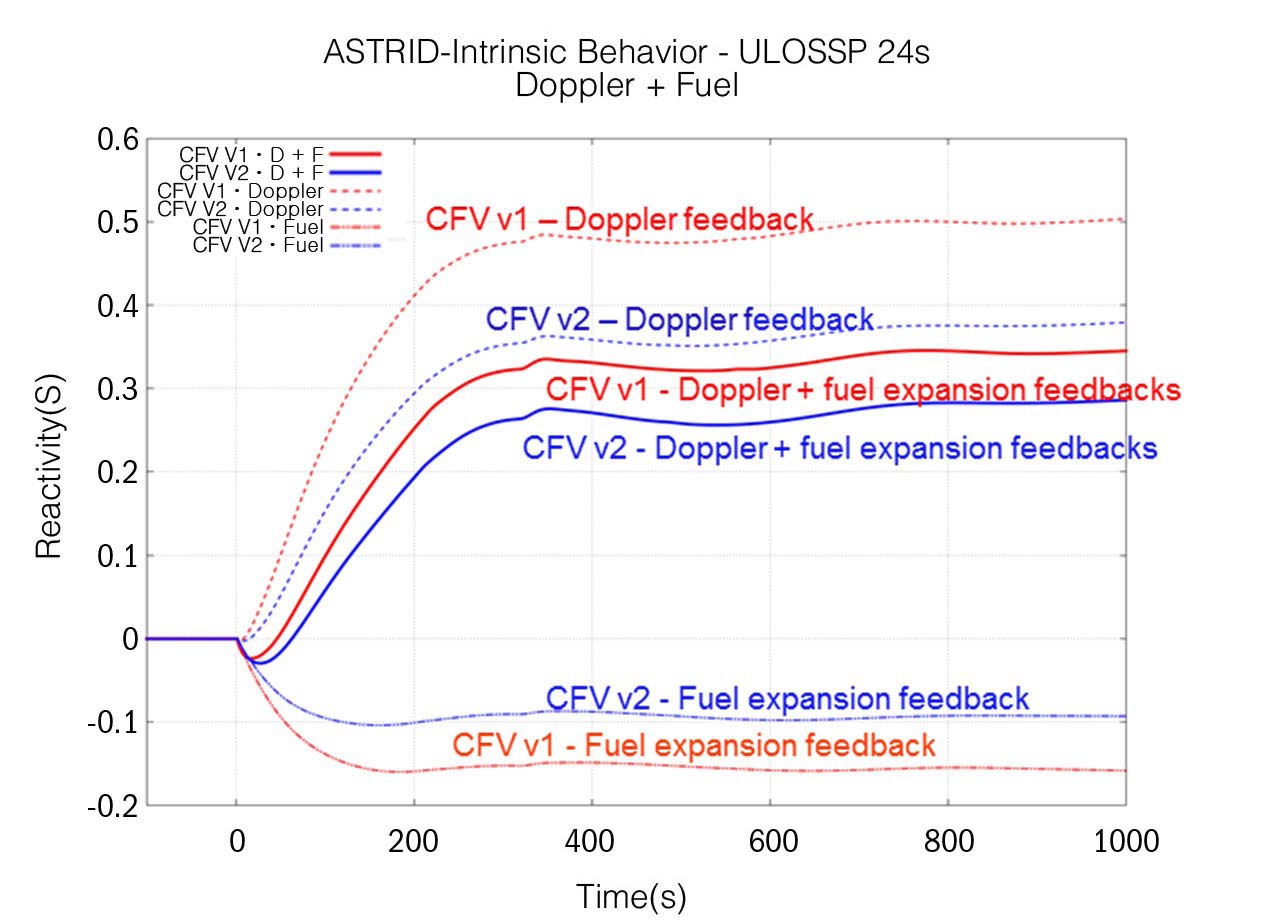
For this transient, the CFV v2 core does not provide the gain expected with the selected design options (strong reduction in the linear power and the power density in particular) because the fuel analysis showed that part of
the fuel did not fill in the pellet-cladding gap before the transient. The graphs in Figure 5 show the significant advantage of the CFV v2 design options in terms of Doppler feedback. However, ‘free-fuel’ operation modifies the neutron feedback related to fuel expansion, which reduces the positive impact of the reduction in the linear power and the power density. Overall, the sum of the feedback (Doppler + cladding expansion) varies little between the CFV v1 and the CFV v2 cores.
Furthermore, the conditions (cold fuel, pellet-cladding gap equal to zero or very low, high power ramp) of pelletcladding interaction due to a power increase during the accidental withdrawal of a control rod, are potentially met for certain CFV v2 core sub-assemblies located near the control rods. The examination of feedback from experiments conducted on accidental control rod ejection-type power transients leads us to recommend that the linear power at the beginning of the life, in the maximum flux plane, is
to remain above a certain limit so that the operating mode of the ASTRID core does not deviate from the known domain. This recommendation will be taken into account in the conceptual design.
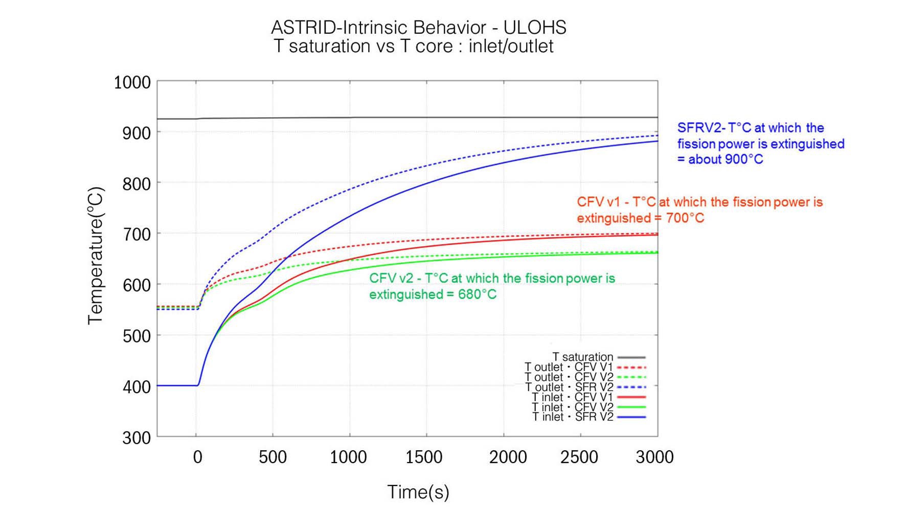
Unprotected-loss-of-heat-sink (ULOHS) transient
The graphs in Figure 6 show the temperature variations at the core inlet and outlet when the secondary coolant pumps are tripped without reactor scram, the steam generators are dried, and the primary flow is maintained. The examined criterion is the isothermal temperature in the primary circuit at which the fission power is extinguished (without inserting the absorbers) thanks to reactivity feedbacks.
In a situation involving the loss of unprotected heat sinks (ULOHS), the CFV core shows a significant gain compared with a SFV2-type core. The CFV core reveals a substantial safety margin relative to the boiling point and a relatively low smothering temperature (to be confirmed). This suggests a robust demonstration in terms of the resistance of the structures over several days, therefore providing more time for conducting operations and restoring safe conditions.
Other transients
Studying the initiators of transients of power (TOP) and control rod withdrawal (CRW) has not provided discriminating elements between the CFV and SFR V2 core concepts.
Certain accidental control rod withdrawal assessments show low safety margins with respect to the criteria considered for the CFV cores. However, design optimisations have been identified.
Conclusion on prevention situations under study (total loss of power in particular) and orientation for the conceptual design
In unprotected total loss of power conditions, according to certain assumptions concerning the chosen design options (e.g. the inertia of the primary pumps leading to a semiflow rate within 24 seconds during the pump trip), the studies show that a CFV-type core can provide a positive safety margin in relation to the boiling point. However, the integration of uncertainties shows that this margin is insufficient vis-a-vis a robust demonstration showing that sodium does not boil. A robust margin will be ensured by adding an additional safety measure (which will be selected and designed during the conceptual design phase) to cover these uncertainties and to achieve conditions which are compatible with the resistance of the structures.
3.2 Studies on Sodium Ebullition
For the study of unprotected loss of flow transients, the criterion is the sodium non-boiling because the level of maturity vis-a-vis the knowledge and mastery of the physical phenomena in the case of sodium boiling in one or more assemblies is considered too low.
R&D studies are launched in parallel to study the phenomenon of ebullition at the scale of one or more assemblies during a total loss of power transient.
It is important to characterize prevention situations beyond the time of onset of ebullition (and to identify possible criteria other than the non-boiling of the sodium) and know the conditions of entry into mitigation situations.
Developments have been made in the CATHARE code and the experimental data base has been examined.
For unprotected loss of flow transients, when the boiling point of the sodium is reached at the core outlet, a stabilized ebullition situation is searched, i.e. the occurrence of which is not accompanied by a sudden drop in flow (due to the increase of friction) which would lead the clads to dry-out.
This possibility of stabilized ebullition has been demonstrated experimentally by a team from CEA in the early 1980s at the scale of a bundle of 19 pins and is characterized by a boiling front located in the last few centimetres in the upper part of the pin bundle.
CATHARE 2 simulations performed in 2012 suggest such behaviour. In the case of CFV cores, as a result of negative coolant density feedback when the plenum is drained, ebullition in this area leads to a power decrease, which goes in the direction of the sought cooling as far as it does not induce penalizing hydraulic instabilities. However, this behaviour will have to be finely characterized.
Simulated phenomenology is complex and will require a major effort in models qualification. This work will be based initially on the SENSAS experimental program with air and water. The R&D effort of qualification should also cover the coupling between hydraulic and neutronics. The objective will be to demonstrate that the occurrence of the sodium boiling leads to a global decrease of the power in the subassembly.
3.3 Severe Accident Mitigation Situations
These studies involve taking into account restrictive decoupling criteria to ensure a robust demonstration and an assessment that is as conservative as possible so it overrides any dependency in terms of the development of the scenario.
For a widespread core meltdown following an unprotected loss of power, the transient calculations show that, due to its intrinsic characteristics, the thermal power has already dropped significantly when the CFV core reaches the degradation phase, compared with the SFRV2 core (see Figure 2 and Figure 4). A reduced power, due to the negative sodium void effect in the event of sodium draining, would lead to a different phenomenological degradation sequence for the CFV core compared with the known reference sequences : the cladding would melt first and then the fuel.
The first assessments of these conditions lead us to believe that there should be no major reactivity insertion and that the core behaviour would probably improve in terms of the release of mechanical energy compared with the SFR V2 core.
These conditions would lead to core degradation, which is preferably controlled via the thermal conditions, and supports the assumption of a stratified geometry maintained for a certain period of time by the fertile plate in the inner core. As a result, it is expected to take significantly longer to reach molten pool conditions. This delay could be exploited to implement additional mitigation measures.
The improved behaviour of the CFV core compared with the SFRv2 under these degraded conditions has to be confirmed in the conceptual design phase.
The need to complete the GENESIS neutronics programme on the critical MASURCA model has been confirmed, regardless of the core concept. These CFV and SFRv2 cores fall outside the scope of existing experimental qualification when considering the neutron spectrum, given their different characteristics compared with the previous core designs (such as Superphenix or the EFR) in terms of volume fractions of fuel and sodium. Due to its inventory of fissile material, the MASURCA model can be used to develop an experimental core that is representative of the physics of large cores (better representation of spatial effects), which is essential for the CFV or SFR V2 core concepts.
A prior experimental programme aimed at analysing effects of plenum addition and internal fertile zone insertion is starting in the BFS reactor of Obninsk IPPE in collaboration with Russia.
It is recommended to carry out a phase-3 qualification irradiation using a fuel prototype on the scale of the pin and bundle. The purpose of this irradiation using a fuel prototype is to validate the design, manufacturing, and operating process of the pin bundle in representative conditions. Indeed, the large pin/small spacing wire geometry is innovative compared to the pin bundle geometry of previous reactors.
The last qualification phase, known as phase 4, aims to qualify the industrial product and should be carried out in the ASTRID reactor during the transition from the startup core to the equilibrium contractual core9.
The level of qualification of both the CFV and SFR V2 fuel concepts are considered to be similar. For a heterogeneous CFV-type fuel, the examination of the ZEBRE irradiation programmes carried out in Phenix on heterogeneous pins showed that, in the fissile areas, the behaviour of the fuel remained similar to that of homogeneous fuel and that the interfaces with the fertile areas did not present particular phenomenologies.
Besides the ZEBRE program, it will be possible to mainly base the qualification of CFV fuel on the postirradiation assessments of 1) the PAVIX 8 experiment carried out in Phenix in the nineties, consisting of full sub-assemblies of heterogeneous pins with an AIM1 cladding (cladding material selected for the first ASTRID core loadings) and 2) the CZAR 1 experiment, consisting of the re irradiation at high burn-up of few pins of the ZEBRE experiment.
The following operations are strongly recommended in order to qualify the absorbers:
- Irradiation of specific materials to qualify the coatings of the guide parts exposed to the neutron flux.
- Irradiation of absorber elements, with design and flow conditions as representative as possible of the core upon start-up, to support the validation of the entire design-manufacture-service request process, the qualification of the carbo-thermal B4C, and the demonstration of the lifetime of a jacket.
- Post-irradiation assessments of the Phenix rods.
Concerning the materials, the first cores of ASTRID will be based on the choice of known materials, which have already been tested in Phenix, such as for example EM10 for the material of the wrapper tube and AIM1 for the cladding. However, the CFV concept has design specificities which require a dedicated qualification program related to the welding of the plug/cladding subjected to a higher flux.
A program to acquire additional data of core material behaviour at high temperatures (up to 950℃) was initiated to complete the evaluation of the core behaviour under accident conditions.
The possibility and relevance of conducting fuel melting tests and corium/sodium interaction tests (with and without void conditions) and plugged sub-assembly tests to investigate severe accident issues are being examined with the aim of supplementing the current database related to pin bundles with a reduced hydraulic diameter (common option between the CFV core and the SFRv2 core).
Other test programmes of a more analytical nature are also being considered for the qualification of computational tools.
4.6 Conclusion on the Qualification
The qualification of the fuel, absorbers, and materials will widely be based on the post-irradiation assessments of the irradiation experiments carried out in the Phenix reactor (‘Phenix treasures’ approach). A structured approach was implemented in 2012 to identify relevant objects worth examining for the ASTRID core, as well as to plan transport and the post-irradiation assessments11.
At the current stage of the design studies, no discriminating element has been identified regarding the qualification needs of the two types of cores (CFV and SFRv2). It is therefore possible to consider commissioning the ASTRID reactor with a CFV-type fuel.
The overall concept of the fuel sub-assemblies is mainly based on feedback from Phenix and Superphenix, as well as on a design involving a sub-assembly with a shortened spike (due to the compact pressure-reducing components), a closed leak tight wrapper tube made of EM10 steel, and UPuO2 fuel pin bundles with AIM1 cladding.
A specificity of the CFV concept is that it uses enriched B4C in the lower part of the top neutron shielding in order to comply with the negative sodium void coefficient criterion. Taking into account certain cost and safety constraints, an approach for minimising this quantity is being pursued, including combinations with other absorbing materials such as hafnium.
Due to the risk of core compaction related to dynamic stress (earthquakes, pulse loads), the stiffness of the pads and the plasticity of the sub-assembly spike will be optimised.
It was decided to apply the same control rod and safety rod design principles employed for the French systems such as Phenix, Superphenix and the EFR, which include:
- Aligning the top parts of all the sub-assemblies (fuel and absorbers),
- Maintaining the mobile absorber inside the sheath.
With the aim of reducing the height of the sub-assemblies, the following major options have been retained for the absorbing devices:
- Control rods with a low level and a olive-shaped base,
- Safety rods with a low dashpot and unsegmented absorbing bundle.
A sheath base option involving a fool-proofing system is being studied to avoid the complete insertion of a fuel sub-assembly instead of an absorbing device and to limit and improve the safety demonstration with respect to handling errors.
The reference material for the absorbing components in the first cores is natural B4C and/or B4C enriched at 48% with 10B.
5.3 Reflector Sub-assemblies and Lateral Neutron Shielding
The design of the reflector sub-assemblies and lateral neutron shielding is underway. This design is consistent with progress made in the field of the secondary sodium activation criteria, the acceptable tritium source term in the ASTRID reactor, and the primary system design requirements.
Various materials and design options are being considered for the reflectors and the lateral neutron shielding. They remain open at the present stage of the studies:
For the reflector sub-assemblies: pins or rods made of Sic, MgO, MgAl2O3 or 11B4C.
For the lateral neutron shielding: natural B4C or alternative materials on a hafnium or steel base.
The use of natural B4C makes it possible to minimise the thickness of lateral internal protective devices around the core.
During the AVP2 phase, the aim is to converge towards optimising the design/materials for the reflector subassemblies and the lateral neutron shielding, in relation to the ASTRID specifications described above.
A preliminary analysis of the parameters to be monitored during operation and for detecting incident/accident conditions (corresponding to categories 1 to 4 up to severe accident prevention situations) led to a first proposal for the core monitoring and protection system at the end of the pre-conceptual design phase 1. Here are the R&D options for the monitoring and protection of the ASTRID core:
Controlling the core neutronics: High-temperature fission chambers with a high dynamic range positioned in the primary vessel on the edge of the core or possibly in the core cover plug. Neutron power chambers located outside the vessel are also being studied, particularly for post-accident management.
Detecting plugged fuel sub-assemblies: In addition to the thermocouples above each sub-assembly and fission chamber (for the detection of delayed neutrons), flux distortion meters are also being studied.
Detecting an accidental control rod withdrawal via 2 systems: Thermocouples above each sub-assembly and fission chambers to detect local deformation of the neutron flux layer.
Core movements: Poles with ultrasonic transducers for detecting radial geometry variations in the core.
Handling errors: Measuring the temperature of the subassembly from the handling arm and implementing an identification system using bar codes on the subassembly and by ultrasonic readings.
The objective at the end of conceptual design will be to define an exhaustive list of reference options for the core protection and monitoring system by determining the chosen technologies and by defining the level of diversification, the overall performance expected, and the core monitoring and protection system location in the reactor block.
The pre-conceptual design phase 1 confirmed the safety potential of the CFV cores and the CFV concept is retained for conceptual design. Its potential will have to be consolidated by:
- Characterising the core behaviour in all of the operating conditions (categories 1 to 4 and severe accident prevention situations).
- Defining the choice and the characteristics of the various additional safety measures in relation to prevention and mitigation measures.
- Reinforcing the studies during the sodium boiling phase and the primary and secondary phases of the core meltdown accident.
During the conceptual design phase, a technicaleconomic optimization of the design of the CFV core will also be pursued, including a goal of reducing the overall core radial dimensions.
CFV : “Coeur a Faible Vidange” (low sodium void core)
CSD : Control and Shutdown Device
DSD : Diverse Shutdown Device
CRW : Control Rod Withdrawal
ULOF : Unprotected Loss Of Flow
ULOHS: Unprotected Loss Of Heat Sink