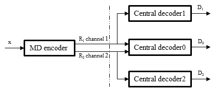
Due to network congestion and delay sensibility, video transmission over a lossy network is always a great challenge. Multiple description coding (MDC) [1] is an attractive approach to solving this problem as shown in Fig. 1. It can efficiently combat packet loss without any retrainsmission, thus satisfying the demand of real-time services and relieving network congestion.
MDC encodes the source message into several bit streams (descriptions) carrying different information, which can then be transmitted over multiple channels [2]. In MDC’s simplest form, two parallel channels are assumed to connect the source with the destination. If only one channel works, the descriptions can individually be decoded to sufficiently guarantee a minimum fidelity in the reconstruction at the receiver [3]. However, when both channels work, the descriptions from the channels can be combined to yield a relatively high fidelity reconstruction.
Numerous MDC techniques have been proposed in recent years, such as the multiple description scalar quantization (MDSQ) proposed in [2]. In MDSQ, two descriptions are created by two coarse quantizers, each ensuring an aceptable distortion when only one of them is received.
These two coarse quantizers can be combined to produce a finer quantizer if two descriptions are received. Further, various types of coding techniques such as subband coding and wavelet coding have also implemented MDC [4-7].
In this paper, we re-visit the MDC scheme based on the pixel domain sub-sampling. In particular, we focus on the quincunx sub-sampling lattice. Instead of applying a horizontal or vertical realignment so as to form regular
square blocks, we retain the quincunx lattice and apply the directional discrete cosine transform (DDCT). Both theoretical analysis and simulation test will be discussed to confirm that an improved coding efficiency can be achieved in our DDCT, as compared to the traditional DCT with horizontal or vertical re-alignment.
In Section II, we briefly introduce the traditional pixeldomain sub-lattice on MDC. The proposed directionally sampled discrete cosine transform (DS-DCT) for the quincunx sub sampling lattice is presented in Section III. Further, we explain how to handle some boundary blocks that remain after the DS-DCT. In Section IV, we describe the experimental setup and present some simulation results. Finally, some conclusions are presented in Section V.
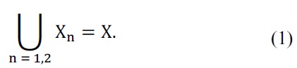
In this section, we will discuss the sub-lattice technique used in the proposed method. Given the source image I, which is typically a subset of Z2, in the proposed method, signal samples are partitioned into two subsets as follows:
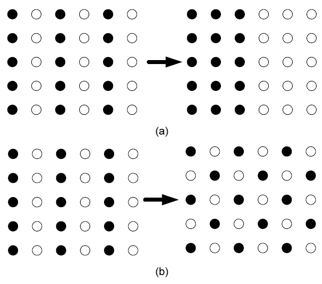
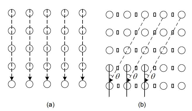
There are two different methods to partition the image into two parts. Fig. 2(a) shows orthogonal sub-sampling, and Fig. 2(b) illustrates quincunx sub-sampling. In the proposed method, descriptions generated by scheme two are used. One of the major advantages of this scheme is the increase in correlation between samples. Under this scheme, two descriptions are generated according to a chess-box pattern, and the Euclidian distance between two neighboring samples is constantly equal to √2. After the splitting process, each description is transformed to the transform domain.
III. DIRECTIONAL COSINE TRANSFORM
The DCT and the discrete wavelet transform used in image compression are implemented by separable onedimensional (1D) transforms in the rows and columns of images.
The conventional
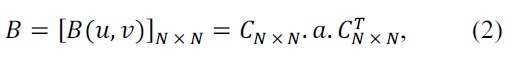
where
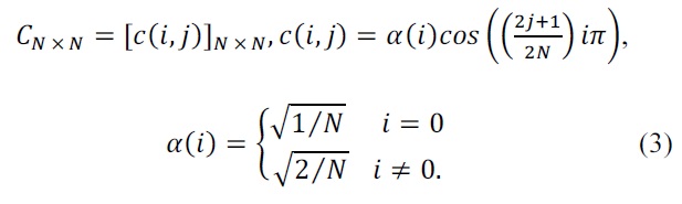
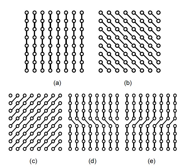
Naturally, the conventional 2D DCT seems to be the best choice for image blocks in which vertical and/or horizontal edges dominate. However, it may cause some defects when it is applied to an image block in which other directional edges dominate. The major shortcoming of the separable transform is that it cannot represent the anisotropic edges in the image sparsely. In order to obtain the better representation of edges in all directions, the given image block is transformed on the basis of the directional DCT in Fig. 3.
In the proposed method, there are in total five directional modes. Among these modes, one is the vertical prediction (mode 0), and the remaining are labeled diagonal down-right (mode 1), diagonal down-left (mode 2), vertical-right (mode 3), and horizontal-down (mode 4), as shown in Fig. 4(a), (b), (c), (d), and (e), respectively.
On the encoder side, the input image is first analyzed block-by-block to decide the transform directions. The 1D DCT transform is performed in each block of the selected direction along the vertical direction. Next, the horizontal DCT is applied in the second step.
On the decoder side, when only one side description is received, the main task of the decoder is to interpolate the missing sub-image from the received sub-image. Although the proposed method involves the use of the directional data, all pixels in the partitioned blocks share a common direction
and the lost description is estimated from the four connected neighbors by using the conventional bilinear interpolation method. Since there are numerous interpolation algorithms for preserving the original textue contents of an image, we can enhance the quality of the reconstructed image by selecting any of the appropriate interpolation schemes.
Similarly, when two descriptions are simultaneously available at the decoder, a straightforward method is to decode the two descriptions simultaneously and then merge the two sub-images. Since each side description is compressed using quantization, any decoded pixel value from one description is only an approximation of the original.
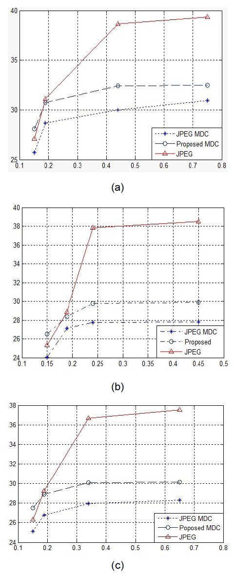
Several experiments were conducted, and their results are presented in this section in order to evaluate the performance of the proposed image MDC scheme. The implementation of the new MDC scheme is integrated into JPEG coding, with the directional transform replacing the original 2D separable rectilinear discrete cosine transform.
Naturally, the JPEG MDC scheme is used as a benchmark for performance comparisons in terms of the peak signal-to-noise ratio (PSNR), where the input image is first split into two descriptions by quincunx lattice sub-sampling and then coded individually by JPEG coding.
To make a fair comparison, we also adopt the proposed texture-oriented interpolation and data fusion algorithms for the central decoding of JPEG MDC.
Two JPEG test images (Lena and Barbara) having a resolution of 512 × 512 are used in our experiments. They are split into two descriptions, each of which is a quincunx lattice. Each description is compressed using JPEG coding and the proposed scheme.
We evaluate the PSNR performance of a side decoder when only one description is received. As proposed, the full-resolution images are reconstructed from the received side description by the texture orientation interpolation method. For the sake of comparison, we also compute the PSNR results of the widespread linear interpolation method when applied to the received quincunx image, as shown in Fig. 5. Since the two descripttions are balanced in our experiments, it suffices to list the PSNR values for description 1 of the proposed MDC scheme. The PSNR values shown in this figure are calculated over all samples including both the decoded and the interpolated images. The rates are also calculated over all samples in terms of a fullresolution image. One can observe that at low rates (e.g., 0.125 bpp), the two interpolation methods perform roughly the same, with only a small advantage to the texture orientation method. This is due to the lack of highfrequency components in the received side description at a low rate.
In this paper, we proposed a new MDC scheme using the directional DCT transform. The input image was directly split into two descriptions in the pixel domain using quincunx lattice sub-sampling. Using DDCT, we represented the image pixels oriented in different directions perfectly. The experimental results confirmed that the proposed directional MDC scheme could outperform the JPEG MDC scheme by up to 0.9 in the cases of both side decoding and central decoding.
Now, let us turn to channel modeling. Due to the highly frequency-selective nature of underwater channels, multicarrier modulation (e.g., orthogonal frequency-division multiplexing) is an attractive choice for reduction in receiver complexity. For analytical convenience, coding is assumed to be performed over a subchannel in a slot experiencing relatively flat fading (through channel coding across all the subchannels, full frequency diversity can be utilized, resulting in a better outage performance, which remains for further work). In this work, we focus on a subcarrier under the assumption that the same relay technique is applied to every subcarrier.
As stated earlier, suppose that the processing delay, taking place due to a variety of operations (e.g., receiving and reading a packet), at the relay is negligible as compared to the propagation delay in water (the propagation speed of an acoustic signal in water is around 1,500 m/s
When the two instantaneous full-duplex relay schemes are used at a certain subcarrier (symbol), the output signals at the relay
and
where
For the AF transmission, the transmitted symbol at
where
For DF transmission, the relay processes
In this section, the DMT curves for three-node under-water acoustic systems using the AF and DF protocols are analyzed after briefly reviewing DMT
Let
and