After it was introduced in the early 1940s, holography has attracted the interest of many researchers because of its ability to record three-dimensional (3D) information. However, the existing holography stored and distributed in the form of analogue films has many constraints with respect to its commercialization be-cause it uses a laser as the coherent light, which requires a limited space, such as a darkroom, to record interference patterns, and is very sensitive to the surrounding environment, such as vibrations, thus requiring a stable optical system [1].
These problems have gradually been overcome with the digitization of devices that generate, acquire, store, process, and display holograms. In particular, it is relatively easy to create a hologram by using computer-generated holography (CGH) techniques [2]. CGH techniques use a ray-tracing method to calculate the diffraction of light. This method considers the object to be a set of multiple points and then sums these points after calculating the intermediate hologram for each point. Consequently, this method requires a considerably large amount of calculation [3]. If it is intended to generate a large number of digital holograms, the amount of calculation and the time required increase exponentially. This problem is a significant obstacle in a realtime hologram service. The purpose of this study is also to increase the calculation speed of CGH. We analyze a previously proposed method [4] to find the regularity between a depth-map image and a digital hologram. Then, we reduce the number of calculations, the partial multi-plication, and the partial addition required for CGH in order to increase the calculation speed.
Section II introduces the CGH method, and Section III explains the proposed fast CGH algorithm. The experimental results of the proposed algorithm are described in Section IV, and Section V presents the conclusion.
II. COMPUTER-GENERATED HOLOGRAM
A system for digital holograms uses electronic equipment, such as CCD cameras instead of optical ones to record the interference pattern of holography and transmit it as video signals. The image is reconstructed at the receiver side by illuminating a laser beam onto the received interference pattern uploaded on a spatial light modulator.
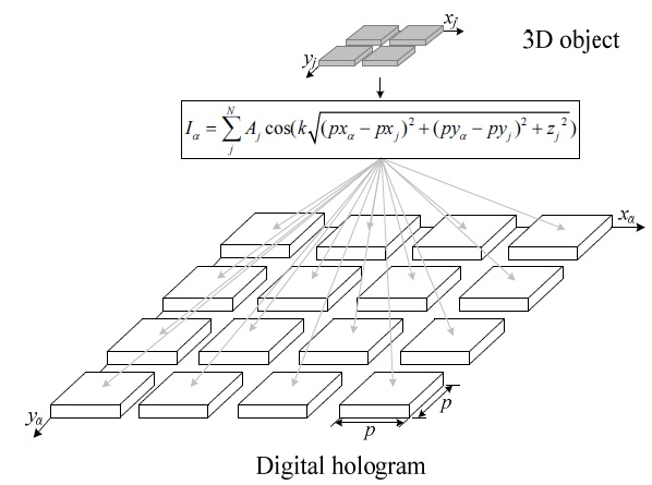
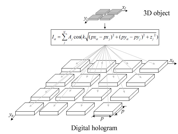
This section describes the CGH calculation method [5] and one using the recursive addition system. The CGH generating equation is defined in Eq. (1):
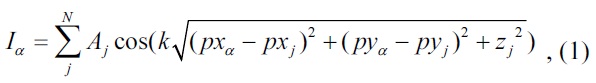
where
Fig. 1 shows a sample coordinate array system for the 3D object and the digital hologram to apply the CGH method, where the 3D object is 2 × 2 pixels in size, and the captured digital hologram is 4 × 4 pixels in size. To generate a digital hologram with this setup, the calculation of Eq. (1) must be carried out 64 (2 × 2 × 4 × 4) times.
If Eq. (1) is approximated to the first term after the Taylor expansion, it could be expressed as Eq. (2).
Here,
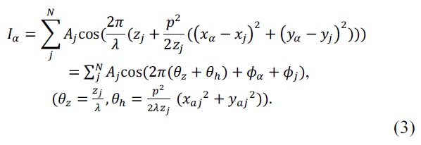
Here,
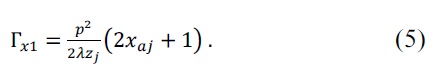
In the case of n = 1, that is,
Meanwhile, in the case of n = 2,
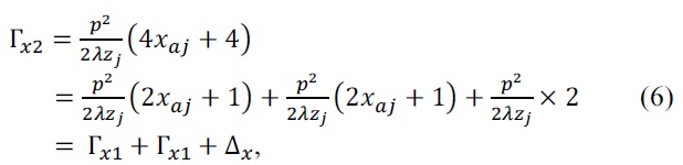
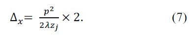
where
Again, when
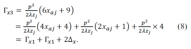
When n = N,
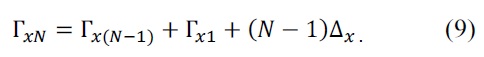
From Eq. (9) it is clear that, once the first column (the leftmost pixel) of a row of a digital hologram (
At this time, we name the CGH calculation in Eq. (2) the
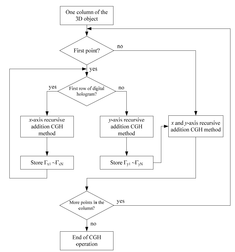
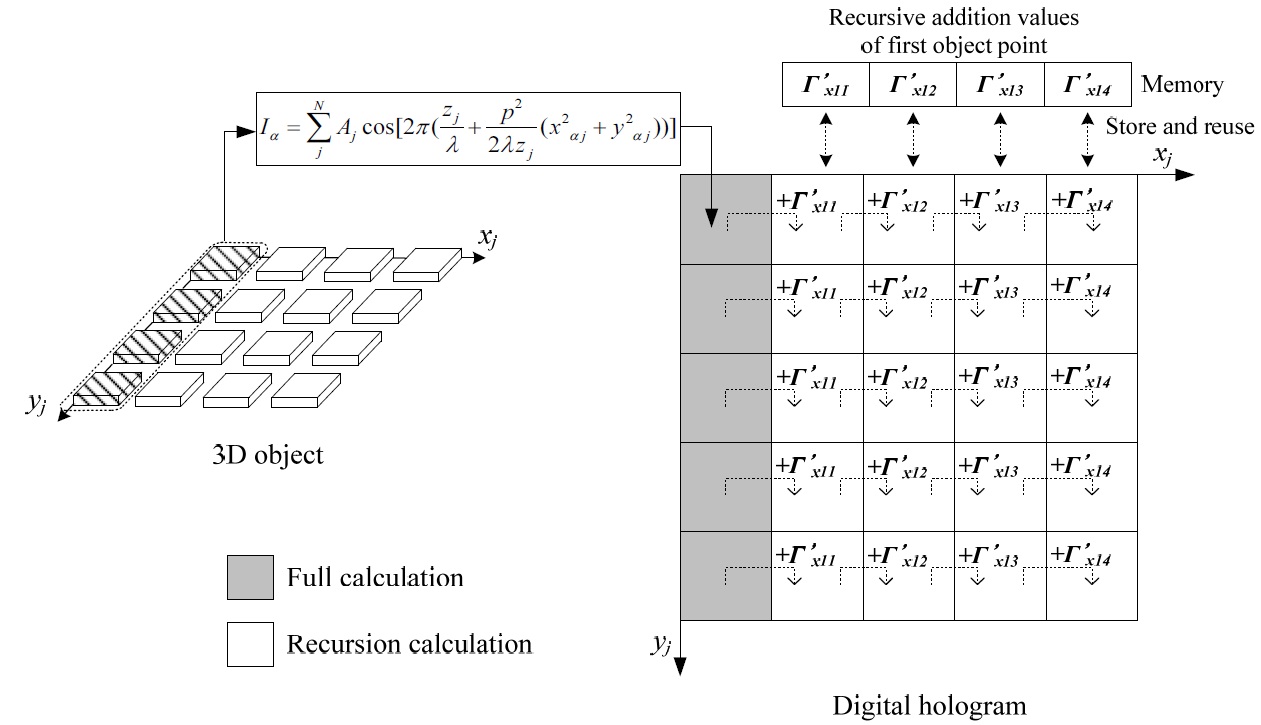
This section proposes a CGH algorithm performing recursive addition techniques in both the x- and y-axis directions as discussed in [5]. The operation procedure of the proposed algorithm shown in Fig. 2 is as follows:
1) Carry out the CGH calculation of the x-axis recursive addition system on the first row of the digital hologram with the first point located on the same column of the 3D object.
2) Store the Γx1 to ΓxN values calculated during the calculation carried out in accordance with step 1.
3) Perform the CGH calculation of the y-axis recursive addition system for the first coordinate of the second row of the digital hologram on the basis of the first coordinate of the first row.
4) Store the Γy1 to ΓyN values calculated during the operation specified in step 3.
5) Starting from the second coordinate operation of the second row of the digital hologram, add the values stored in accordance with step 2 in sequence.
6) Carry out the x- and y-axis recursive addition on the second point of the 3D object located on the same column, using the values stored in accordance with steps 2 and 4.
7) Repeat the calculation specified in steps 1 to 6 on the points located on the column next to the 3D object.
Fig. 3 shows the recursive addition CGH algorithm covering all the coordinates of the hologram of the points on the same column of the proposed 3D object. The proposed algorithm performs the complete calculation at a level on par with the number of points of the 3D object, and the remaining values of the hologram coordinate array are processed as a recursive calculation using the recursive addition technique, thereby increasing the speed of the operation.
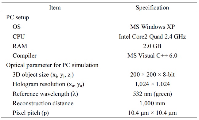
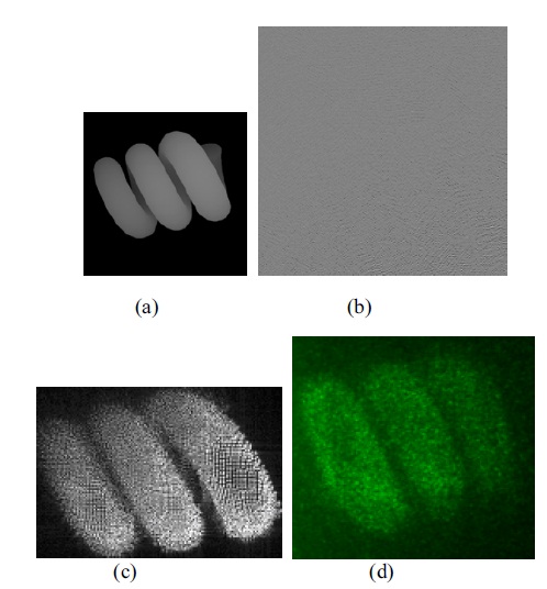
The experimental environments and parameter values used in our implementation are listed in Table 1. The 3D object used a 200 × 200 depth-map image created by CG, and the light intensity of each point was replaced by the pixel value of the depth-map image. The digital hologram to be generated was set in the green channel (532 nm) and the grayscale (8-bit) measuring 1,024 × 1,024, considering the reconstruction environment.
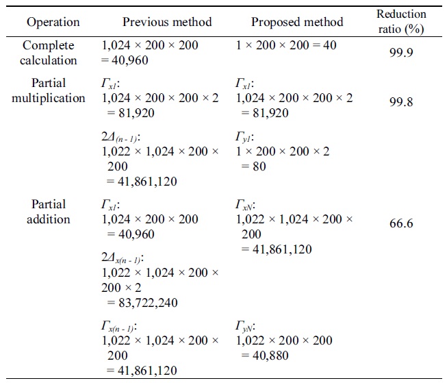
Table 2 presents a comparison of the number of operations between the previous method and the method proposed in this paper. Here, the sizes of the 3D object and the hologram were assumed to be 200 × 200 pixels and 1,024 × 1,024 pixels. Table 2 shows that the numbers of complete calculations, partial multiplications, and partial additions are reduced by 99.9%, 99.8%, and 66.7%, respectively. The reduction rates in this case are the values calculated on the basis of only the number of adders, subtractors, and multiplication operators used. Accordingly, they are not the values that carry direct, proportional relations with the speed of the CGH operation.
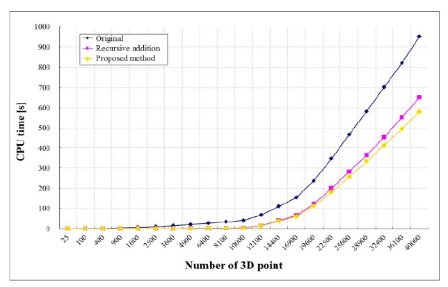
Fig. 4 shows the results of measuring the CPU time of the CGH algorithm proposed in this paper and the previous methods. As shown in Fig 4, the recursive addition operation covering the whole areas of the hologram increased the calculation speed by more than 30% compared with the previous method.

Experimental setup
[Table 2.] Comparison of computer-generated holography calculation time (×103)

Comparison of computer-generated holography calculation time (×103)
Fig. 5 shows the results of measuring the CPU time of the CGH algorithm proposed in this paper and of the previous methods [4]. For the sake of comparison, the CPU time of the proposed algorithm and that of the earlier methods were measured while increasing the number of points of the 3D object.
This paper has proposed an algorithm that increases the calculation speed of the CGH algorithm used when the real or virtual object is transformed into a digital hologram.
The proposed algorithm is a technique that can reduce the overall operation time by carrying out the CGH operation previously carried out on the entire coordinate array of the digital hologram covering one point of the 3D object only on the first coordinate, by recursively adding the previously calculated values to the resultant values calculated from the first coordinate for the remaining coordinates. The proposed algorithm was compared with the previous method, and the results showed that the operation speed increased by approximately 30%.
It is expected that the proposed recursive addition CGH algorithm covering the entire coordinate array of the hologram will be a core fundamental technology of the holographic 3DTV system for the next-generation TV.