Many types of mobile computers have been introduced since the 1990s, such as personal digital assistants (PDAs)/enterprise digital assistants, smartphones, tablet computers, ultra-mobile PCs, and wearable computers [1]. Regalado [2] claims that mobile computers are spreading faster than any other consumer technology in history. Their performances have recently been improved rapidly with respect to supporting various multimedia functions and improving the user-friendliness of the interface. Further, because of the rapid improvement of wireless Internet technology, mobile computers can process large amounts of data at high speeds. As a result, it is feasible and easy to implement a remote monitoring system utilizing mobile computers in various management areas. For example, by using a PDA, Xin et al. [3] developed a new model of a wireless telemedicine physiological monitoring center utilizing a PDA and Laboratory Virtual Instrument Engineering Workbench (Lab-VIEW). De Sousa et al. [4] developed a monitoring and controlling household electric system (i.e., washing machine) using a wireless communication network and a PDA user interface with LabVIEW. Further, Bae et al. [5] developed a buoy monitoring system using a PDA with LabVIEW to manage the buoy.
However, recently, there has been an increase in the number of tablet PC users. A study from the Online Publishers Association (OPA) in 2012 shows that 31% of Internet users in the US reported owning a tablet [6]. Because of its portability, tablet PCs have been employed in various research areas to develop a monitoring system, particularly in the healthcare sector to monitor patients, in the energy sector to monitor energy consumption, and in the environmental sector to collect environmental data on land and in the ocean. For example, Tang et al. [7] developed a mobile environmental monitoring system using a tablet PC to monitor meteorological data, such as air temperature, wind speed, and humidity for a village in China. For an oceanic environment, SignalGeneriX [8] developed and launched the Wisense Ocean remote monitoring platform that supports the deployment of low-powered distributed networks of sensors for real-time remote monitoring and control of oceanic, environmental, security, and military applications. The Wisense Ocean consists of four subsystems: the Wisense Data Buoy, the Secure Remote Data Storage Server, the DataView Remote Monitoring Web Platform, and the Automatic Notification and Alert System. The Wisense remote monitoring Web platform provides a fully customizable interface to the users for controlling their deployments and accessing their data in real time from almost anywhere in the world [9].
In this paper, a tablet PC-based monitoring system with LabVIEW will be described, particularly for oceanic applications, in order to monitor them in real time and easily access them from any part of the world that is connected through the Internet.
In order to safely operate and manage various offshore facilities, we need to collect the environmental status information from these facilities in real time. In particular, it is very important to collect information and monitor each region in real time at a marine facility with respect to the area’s pollution status and marine plant/algae status. In this study, a real-time monitoring system was developed to interconnect a marine observatory and a mobile computer such as a tablet PC.
The marine observatory collects marine environment data and marine weather information, such as the wind direction, wind speed, temperature, and humidity. The proposed marine facility monitoring system utilized various characteristics of mobile computers to monitor environmental data and remotely control the system. Typical features and functions of a tablet PC are as follows [1]:
wireless mobile browser functions (using 2G, 3G, 4G, or Wi-Fi);
e-mail and social media devices;
potential cell phone functions;
global positioning system (GPS) satellite navigation;
stills and video camera functions, and photo and video viewing and editing;
e-book reading;
downloadable apps;
portable media player function;
weight of around 0.5?1 kg; and
battery life of 3?12 hours depending on the usage pattern.
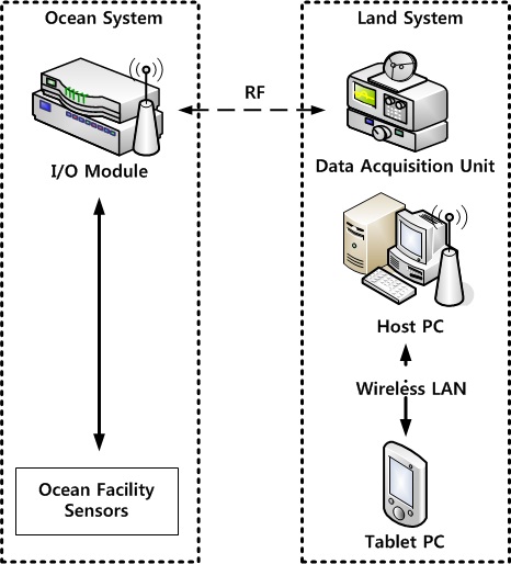
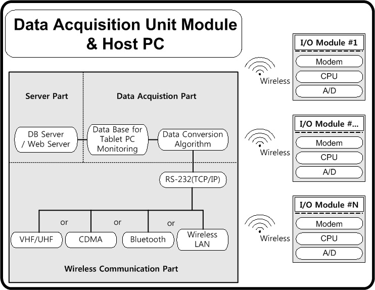
The architecture of the tablet PC-based monitoring system for oceanic applications is as depicted in Fig. 1.
The developed input/output (I/O) module transfers data from various sensors embedded in ocean facilities in the sea to the data acquisition unit (DAU) on land via radio frequency (RF). The tablet PC communicates with the host PC, which consists of a database server/Web server, via a wireless local area network (LAN). This communication makes it possible to monitor ocean facilities in real time without restriction on time and space.
>
A. Concept of Tablet PC-based Monitoring System
Fig. 2 shows a schematic representation of the DAU & Host PC. The DAU & Host PC stores collected data from the I/O module and sends data as required by the tablet PC. The developed system uses a communication standard that can be converted into RS-232 among various communication standards, such as code division multiple access (CDMA), Bluetooth, VHF/UHF, or wireless LAN. The I/O module must be water-tight because it will be mounted on oceanic facilities. The system can be equipped with total of four multi-channel analog inputs.
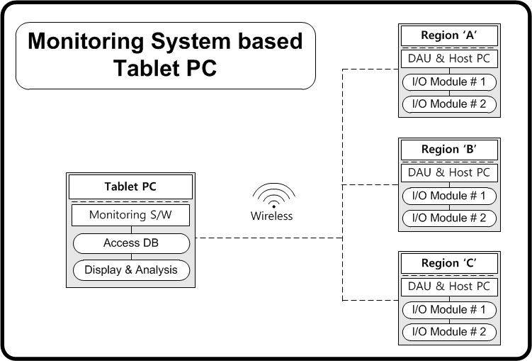
Fig. 3 presents a schematic representation of the tablet PCbased monitoring system. The monitoring software for the tablet PC is individually operated at each tablet PC. It will display and analyze data by connecting to the DAU & Host PC present in each region.
The process of the I/O module program is as follows:
[Table 1.] Description of DAU (PC) protocol

Description of DAU (PC) protocol
[Table 2.] Description of I/O module protocol

Description of I/O module protocol
When the voltage and current values are sent from the I/O module to the DAU (PC), the I/O module converts these values into actual values and sends them in a fivedigit ASCII code (data unit: mV or mA).
The I/O module sends data only when the DAU (PC) requires sending data.
The I/O module converts analog values from all artificial intelligence (AI) modules into digital values using a while loop (the AI module consists of eight channels. Therefore, there are 32 channels in all).
The protocol contains the part that requests data from a specific channel. This protocol makes it easy to monitor a specific channel on the table PC.
This program checks the connection state of the AI module and stores it into a separate variable. When data are sent, this separate variable is also sent together for DAU (PC) processing.
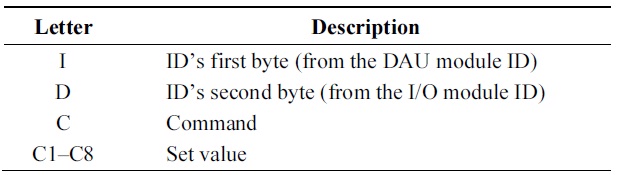
The structure of the DAU (PC) protocol is as depicted in Fig. 4, and Table 1 presents the description of each byte.
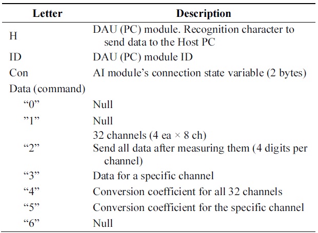
Fig. 5 illustrates the structure of the I/O module protocol, and Table 2 presents the description of each byte.
>
A. Hardware System for the Tablet PC-based Monitoring System
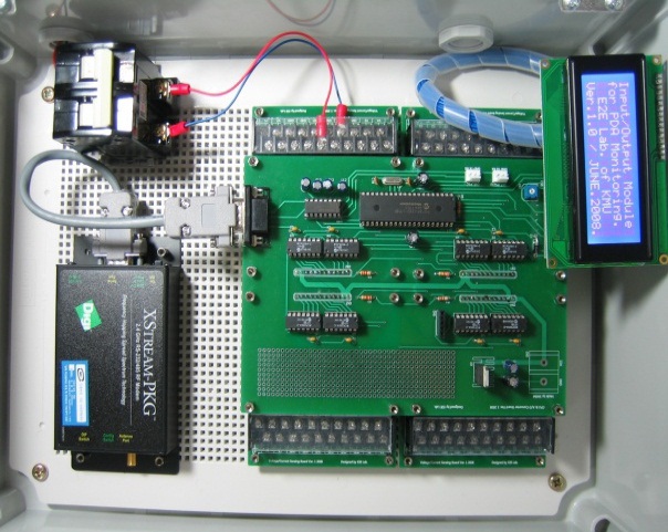
The developed hardware of the I/O module, which processes data such as current and voltage values of the marine facilities, is depicted in Fig. 6. It is a prototype of the communication module that interconnects with the tablet PC. It consists of the RF communication, 32 channels, and the single converter. From the bottom of the case, a current/voltage sensing board is mounted. Each board can measure up to four voltage values and four current values simultaneously. Up to four such boards can be mounted on this prototype. Overall, this prototype can measure up to 16 voltage values and 16 current values simultaneously. The CPU & AD converter board is installed above the current/voltage sensing board and supervises the entire system. Further, a liquid crystal display (LCD) screen is provided to monitor the system in-situ. The bottom left of Fig. 6 shows a modem for the wireless communication.
>
B. Monitoring System for the Tablet PC-based Monitoring System
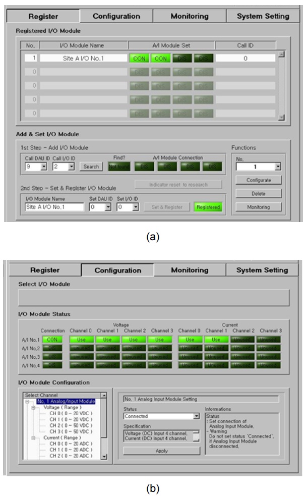
Fig. 7 shows screenshots of the Host PC monitoring system. The “Register” screen is shown in Fig. 7(a), and the “Configuration” screen is illustrated in Fig. 7(b).
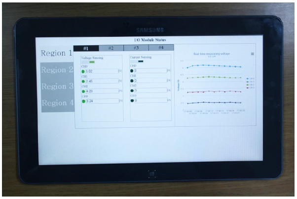
The monitoring system described in this study is a fully Internet-based monitoring platform that enables one to monitor and control remote oceanic applications at any time and from any place where it is possible to access the Internet. Further, it can receive the selected data from a specific local area or a specific I/O module if there is more than one I/O module. The interface is developed to be as convenient as possible for the administrator to use. Fig. 8 shows the monitoring screenshot of the tablet PC monitor.
IV. DISCUSSION AND CONCLUSIONS
The study shows the viability of monitoring and controlling oceanic applications using a wireless communication network and a tablet PC user interface.
The developed monitoring system in this study can monitor marine facilities in real time via the tablet PC and can remotely process and analyze environmental data. Therefore, it promotes the convenience of marine facility management. Because of the possibility of continuous monitoring, it also improves the reliability of data. Overall, it is expected to reduce the maintenance costs of operating various marine facilities.
This developed system’s transferability will be high in the ocean as well as on land. For example, it could be applied to a navigation buoy system that affects most the safety of a ship operation. It could manage and remotely control a floating fish cage in open sea. It could also be used as a management system for an ocean energy power generation system. Moreover, it may contribute towards the development of systems for monitoring areas on land, such as an automation equipment system and a remote monitoring system.