The light emitting diode (LED) is considered a nextgeneration light source since not only is it energy efficient but it also has the long life required for the illumination of homes and offices. The US Department of Energy expects that $15 billion in energy costs per year can be saved if LEDs are used as a light source [1]. For the general purpose of illumination, white LEDs are usually required. Highpower white LEDs required for this purpose could be manufactured after the development of gallium nitridebased LEDs.
Since traditional light sources, such as incandescent light bulbs and florescent lights are being replaced by LEDs, research activities have been focused on the design of LED light fixtures [2] for efficient light emission or enhancement of the lifetime of LED light by designing an optimal heat sink [3,4].
Recently, the research focus has shifted to the design of an intelligent LED lighting system because of the fact that the LED is easily combined with other electronics, such as microcontrollers, a variety of sensors, and wired and/or wireless communication devices to implement intelligent lighting systems. In order to design smart LED lighting systems, the authors surveyed and suggested the choice of power and control hardware in [5]. In [6], an ambient light sensor is integrated on a LED driver chip. A dimming system to control an LED street lamp through ZigBee and
general packet radio service (GPRS) is proposed [7]. If the LED lighting system is combined with a wireless sensor network and uses the location estimation method proposed in [8], the LED lighting system will become more intelligent than ever before.
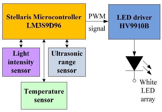
In this study, an intelligent LED dimming system, as shown in Fig. 1, is designed and implemented using an LED driver circuit and multiple sensors―light intensity and ultrasonic range sensors―and is controlled by a microcontroller.
II. DESIGN OF LED DIMMING SYSTEM
For the development of an intelligent LED dimming system controlled by a microcontroller, certain hardware and software design techniques are required.
As shown in Fig. 1, a microcontroller, an LED driver, and a variety of sensors are required to implement the proposed LED dimming system. Basically, the brightness of LEDs can be adjusted by controlling the forward current through the LEDs. There are two possible ways to dim LEDs: analog dimming and digital dimming. Analog dimming is achieved by adjusting the forward current linearly through the LEDs using a data converter, such as an analog-to-digital converter (ADC) or a digital-to-analog converter. On the other hand, digital dimming is commonly used because of its easy implementation and the improved LED driver efficiency. A simple, widely used method of digital dimming is dimming with a pulse width modulation (PWM) signal. The forward current through the LEDs can be adjusted by changing the duty cycle of the PWM signal; this results in controlling the brightness of the LEDs. Many microcontrollers available on the market today are capable of generating PWM signals.
LED dimming without manual control can be realized by integrating sensors into the LED dimming system. In this work, two different sensors―a light intensity sensor and ultrasonic range sensor―are used. The light intensity sensor monitors the ambient light intensity around the LED lighting.
The ultrasonic range sensor provides sonar range information for the microcontroller to control the brightness of the LED light bulb.
In this work, a Stellaris microcontroller, LM3S9D96 [9] manufactured by Texas Instruments, is used for implementing the LED dimming system. A 32-bit microcontroller is used in this work since more intelligent functions, for example, wired light control (that is, digital addressable lighting interface [DALI]), wireless light control (ZigBee or Bluetooth), and visual light communication, can be implemented in a future work. For the LED driver, a Supertex LED driver, HV9910B [10], is used for
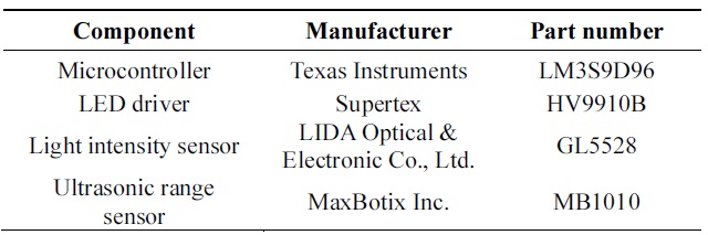
[Table 1.] Major components and their manufacturers

Major components and their manufacturers
generating power for a 7-W 2-chip LED light bulb. The Stellaris microcontroller is connected to the LED driver and controls the output current of the LED driver by changing the duty cycle of the PWM signals.
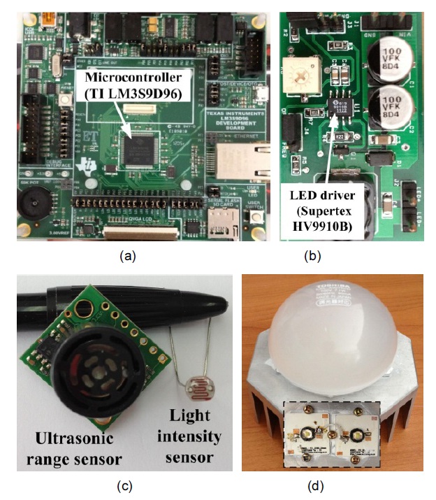
For the light intensity sensor, a CdS photoconductive cell, GL5528 [11] manufactured by LIDA Optical & Electronic Co., Ltd., is used. For the ultrasonic range sensor, a highperformance sonar range finder, MB1010 [12] manufactured by MaxBotix Inc., is used. It provides sonar range information from 6 inches (0.15 m) to 254 inches (6.45 m) at a resolution of 1 inch (0.0254 m). A 7-W 2-chip LED light bulb is fabricated using two LED chips, a heat sink, and a light diffuser in the lab at Wonkwang University. Each LED chip consumes 832 mA at 8.6 V when the duty cycle of the PWM signal is 100%. Photographs of the microcontroller, LED driver, sensors, and LED light bulb are shown in Fig. 2(a), (b), (c), and (d), respectively. The major components and their manufacturers are listed in Table 1.
The various PWM signals generated by the microcontroller and the current consumption of the LED light bulb with respect to the duty cycle of the PWM signal will be discussed in the next section.
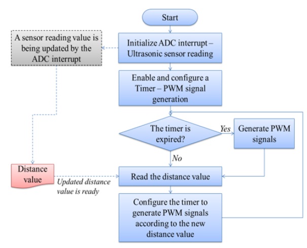
The software implementation for controlling the LED dimming system is as follows: ADC interrupts are used for converting the analog input from the light intensity sensor and the ultrasonic range sensor into a digital value. Timer1 in the microcontroller is used for generating PWM signals. The output of the light intensity sensor and the ultrasonic range sensor is read periodically. In this system, a polling method is used for the sake of simplicity. Fig. 3 shows the overall control structure.
1) Control of ultrasonic range sensor
For reading the ultrasonic range sensor and calculating the distance from the raw sensor value, the following algorithm is implemented in the actual code:
(1) Initialize the ADC interrupt.
① Enable the ADC.
② Enable GPIO port B.
③ Configure Pin 4 of GPIO port B.
④ Configure the ADC sample sequence to read a voltage from the pin.
⑤ Enable the ADC sample sequence interrupt.
(2) Implementation of an ADC interrupt handler.
① Clear the ADC sample sequence interrupt.
② Read a raw ADC value.
③ Convert the raw value to millivolts using the equation Or × VCC × 1,000/Rmax, where Or denotes the raw output value; VCC, the input voltage; and Rmax, the maximum resolution value.
④ Update current millivolt value that will be used for changing the PWM duty cycle to change the brightness of the LED light bulb on the basis of the measured distance. See “3) Control of duty cycle of PWM signals” for more details.
The distance from an output voltage of the ultrasonic sensor can be calculated as follows: VCC is 3.3 V in the Stellaris board. The voltage resolution of the sensor is 512, which means VCC can be evenly divided by 512. The unit millivolt (mV) for an inch can be calculated by dividing 3,300 mV by 512 (= 6.45 mV). Therefore, the output voltage of the ultrasonic range sensor can be used for measuring the distance by dividing the raw voltage by the unit voltage. For example, if the output voltage of the ultrasonic range sensor is 500 mV, the distance will be 500 mV/6.45 = 77.52 inches.
The light intensity sensor can be controlled by a similar algorithm for the ultrasonic range sensor.
2) Generation of PWM signals
As mentioned previously, Timer1 in the microcontroller is used for generating PWM signals. The following algorithm is implemented in the actual code:
(1) Initialize the board.
① Set the clock to run directly from the external crystal/oscillator. A 16-MHz crystal is used.
② Enable the Timer1 peripheral.
③ Enable GPIO port E.
(2) Configure the timer.
① Configure the GPIO pin muxing for the Timer/ CCP function.
② Configure the CCP setting for CCP3. Pin 4 of GPIO port E is used.
③ Configure Timer1 as a 16-bit periodic timer.
④ Set the Timer1 value to 50,000.
3) Control of duty cycle of PWM signals
The following algorithm is implemented in the actual code to control the duty cycle of the PWM signals.
(1) Disable Timer1.
(2) Read current timer load value Lt that was set to 50,000 in this algorithm.
(3) Acquire distance information from the ultra-sonic range sensor. See “1) Control of ultrasonic range sensor” for more details about acquiring distance information from the ultrasonic range sensor.
(4) Acquire the on-duty percentage oon from dcur/dmax where dmax denotes the maximum distance to measure and dcur represents the current distance information.
(5) Set the timer with Lt × (1 - oon).
(6) Enable the timer.
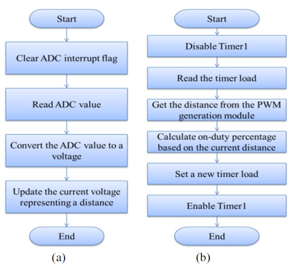
Fig. 4(a) and (b) show the overall procedures of these two software modules.
>
A. Setup of LED Dimming System
In this work, the Stellaris microcontroller development board from TI is used for simplifying the hardware development process. To the microcontroller development board, the ultrasonic range sensor and the light intensity sensor are connected through analog interface ports of the microcontroller.
An LED driver board generating stable power for the 2- chip LED light bulb is connected to the microcontroller development board that provides PWM signals. The LED dimming system described above is shown in Fig. 5. For the sake of convenience, the top view of the LED dimming system is shown in the inset of Fig. 5.
>
B. Performance of LED Dimming
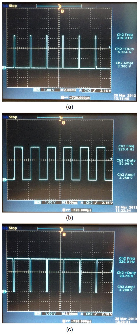
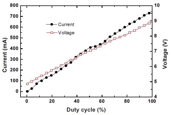
The various PWM signals from the microcontroller are shown in Fig. 6. PWM signals with the positive duty cycles of 6.25%, 50%, and 93.75% are shown in Fig. 6(a), (b), and (c), respectively. The frequency of the PWM signals is set at 320 Hz, since the minimum output frequency is known to be 300 Hz for flicker-free LED dimming. As expected, the PWM signal at the very low duty cycle is a very narrow pulse as shown in Fig. 6(a). On the other hand, at the very high duty cycle shown in Fig. 6(c), the PWM signal is almost flat at the 3.3 V level. At the 50% duty cycle, the PWM signal is just a rectangular waveform. In this work, the LED dimming is implemented at a resolution of 8 bits(that is, 256 levels). In order to quantify the LED dimming level with respect to the duty cycle of the PWM signal, the current consumption by the 2-chip LED light bulb is measured and shown in Fig. 7. The voltage at the input of the LED light bulb is also measured. It is clearly shown that the LED dimming level is controlled linearly by the duty cycle of the PWM signals. This linear characteristic is essentially the performance of the LED dimming system, since it allows the fine dimming range controlled by the microcontroller through PWM signals.
>
C. Control of Multiple Sensors by Software
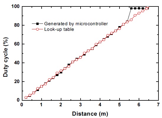
As an example of the software algorithm, Fig. 8 shows the duty cycle of the PWM signals generated by the microcontroller with respect to the measured distance from the LED light bulb by the ultrasonic range sensor. In the driver software, there is a look-up table for the duty cycle versus the distance from the LED light bulb. When the ultrasonic range sensor detects an object, the microcontroller calculates the distance between the LED light bulb and the object and generates a PWM signal according to the look-up table. As shown in Fig. 8, the generated duty cycle is almost the same as the duty cycle in the look-up table in the driver software.
At a distance of more than 5.6 m, the microcontroller generates a duty cycle of 98% because of the limitation of the ultrasonic range sensor. Although the manufacturer specifies that the maximum detectable distance is 6.45 m, the actual distance measured by the sensor in the experiment is 5.6 m. This produces the difference between the generated duty cycle and the duty cycle in the look-up table as shown in Fig. 8.
Using a microcontroller with multiple sensors―light intensity sensors and ultrasonic range sensors―in this work, we have designed and implemented an intelligent LED dimming system. Further, a 256-level LED dimming system is realized by controlling the duty cycle of PWM signals from the microcontroller. When the LED dimming function is combined with the multiple sensors that provide the distance information from any objects and the ambient light intensity around the LED light bulb, the brightness of the LED is automatically controlled. The proposed intelligent LED dimming system can work together with a wired and/or wireless network interface to realize ubiquitous LED lighting systems.