Underwater networks have attracted considerable attention due to recent advances in acoustic communications technology [1,2]. However, underwater acoustic channels normally have limited bandwidth and severe signal attenuation as well as very low propagation speed, which are the main features that distinguish underwater systems from wireless radio links.
In underwater networks, a natural way to partially overcome such difficulties and to further improve the performance is the use of cooperation between terminals. Cooperative relay techniques have the advantages of extending the coverage and enhancing the end-to-end quality in terms of capacity and reliability (e.g., [3-5] for terrestrial radio networks). In the case of underwater networks, it was shown that cooperation gains could be achieved via simple maximum ratio combining [6] or distributed spacetime block coding [7]. To support the practical implementation of such a cooperative framework, a sparse channel estimation method [8] and a receiver structure including various detectors [9] were introduced.
In a quasi-static channel environment in which the transmitters do not have perfect channel state information (CSI), a fundamental performance measure to evaluate various cooperative strategies is the diversity-multiplexing tradeoff (DMT), originally introduced by Zheng and Tse [10] for point-to-point multiple antenna systems. In the high signal-to-noise ratio (SNR) regime, they defined the diversity gain as the rate of decay of the error probability (or outage probability) and the multiplexing gain as the rate of increase in the transmission rate, with increasing SNR. This work has stimulated a number of research efforts to extend the optimal DMT for wireless radio networks with cooperation [5,11]. For underwater systems, since only a small amount of CSI via delayed limited feedback may be available at the transmitters due to the low speed of sound in water (i.e., the slow propagation velocity), thus causing outages, characterizing the DMT is crucial in practice.
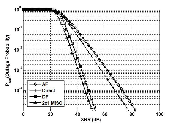
In this paper, we analyze the DMT and outage behavior for a three-terminal underwater network using an acoustic signal, where a single relay helps a source to better transmit its message to a destination. In the network, the construction of an optimal cooperative strategy in terms of DMT remains a challenge. Since the processing time, due to a variety of operations, at the relay node does not cause significant changes in the overall delay along the source-relaydestination path owing to the long propagation delay over an acoustic channel, the existing transmission protocols may operate in a fundamentally different manner from those in wireless radio channels and thus, need to be explained accordingly. For an underwater system, two relay transmissions, called decode-and-forward (CD) and amplify-andforward (AF), are briefly described. Our results then indicate that a naive instantaneous DF relay scheme achieves the same DMT curve as that of 2 × 1 multiple-input singleoutput (MISO) channels, thereby guaranteeing the DMT optimality. Meanwhile, the DMT achieved by an instantaneous AF relay is upper-bounded by that of a direct transmission with no cooperation. To validate our analysis, computer simulations are performed with respect to the outage probability for a fixed target rate.
The rest of this paper is organized as follows: Section II describes the system and channel models. The DMT curves for underwater systems are derived in Section III, and the numerical evaluation is discussed in Section IV. Finally, we summarize the paper with some concluding remarks in Section V.
Throughout this paper, the superscript
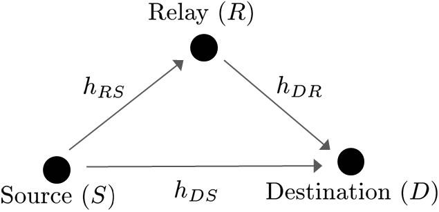
Consider a three-terminal relay system [3], in which a source
Thus, there exists a direct link from
Now, let us turn to channel modeling. Due to the highly frequency-selective nature of underwater channels, multicarrier modulation (e.g., orthogonal frequency-division multiplexing) is an attractive choice for reduction in receiver complexity. For analytical convenience, coding is assumed to be performed over a subchannel in a slot experiencing relatively flat fading (through channel coding across all the subchannels, full frequency diversity can be utilized, resulting in a better outage performance, which remains for further work). In this work, we focus on a subcarrier under the assumption that the same relay technique is applied to every subcarrier.
As stated earlier, suppose that the processing delay, taking place due to a variety of operations (e.g., receiving and reading a packet), at the relay is negligible as compared to the propagation delay in water (the propagation speed of an acoustic signal in water is around 1,500 m/s [13], which is five orders of magnitude lower than that of a radiowave). This is because the processing delay is at most on the order of a few milliseconds, while the propagation delay can be of several seconds according to the distance between nodes. Such an assumption was similarly made in [14] only when the AF relay was used in the underwater system even if the AF protocol could not utilize the full spatial diversity, which will be specified in Section III-A. In this model, the symbol generated at
When the two instantaneous full-duplex relay schemes are used at a certain subcarrier (symbol), the output signals at the relay
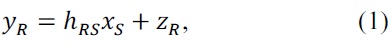
and

where
For the AF transmission, the transmitted symbol at
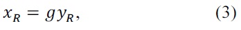
where
For DF transmission, the relay processes
In this section, the DMT curves for three-node under-water acoustic systems using the AF and DF protocols are analyzed after briefly reviewing DMT [10].
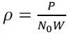
Let
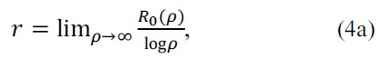
and
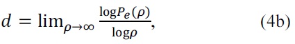
where
and
Pe(ρ) ? ρ-d
is identical to (4b), and ? is referred to as the exponential equality.
The optimal DMT curve represents the maximum di-versity gain for a given multiplexing gain
satisfies
Pout(R0,ρ) ? ρ-d*(r),
where
In this subsection, we show that the simple instantaneous DF relay scheme achieves an optimal DMT curve. An upper bound on the DMT based on an instantaneous AF relay is also derived for the sake of comparison. We start from the following lemma:
Lemma 1.

and
The proof of this lemma is presented in [19]. From Lemma 1, it can be easily concluded that
Theorem 1.
is achievable.
I=log(1+ρ|hDS|2 + ρ|hDR|2),
which is the same as that of a 2×1 MISO system with the input covariance matrix
under the quasi-static channel assumption [20]. If
I=log(1+ρ|hDS|2),
which leads to the same performance as the direct trans-mission case with no cooperation. Since the two aforemen-tioned events are mutually exclusive, the outage probability
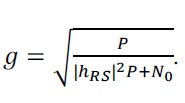
Pr{|hRS|2 ≥ g(ρ)} Pr{|hDS|2 + |hDR|2 < g(ρ) } + Pr{|hRS|2 < g(ρ)}Pr{|hDS |2≥g(ρ)},
where
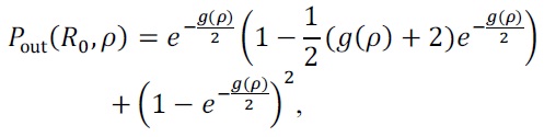
whose high SNR behavior is readily shown to be
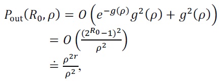
due to the fact that
Further, a DMT upper bound based on an AF relay can be found as follows:
Theorem 2.
d*(r) = 1 - r.
yD = (ghDRhRS + hDS)xS + zD.
Here, it is seen that
On the basis of Theorems 1 and 2, we present the following interesting discussion regarding performance comparison.
Remark 1. To verify the optimality, we consider an upper bound on the DMT in three-node underwater systems by assuming a genie-aided perfect cooperation between