A number of techniques have been exploited to overcome the limitations in the conventional design approaches to filters. For example, Allison [1] modified the configuration of the parallel edge-coupled filter into multiple coupled resonators to reduce its size. Yu and Chang [2] employed openloop resonators coupled with crossing lines to reduce the filter size and to give an elliptic function response; the constraint in the size minimization was rendered with half a guided-wavelength
Alternative solutions have been sought with metamaterials (MTMs), as in Caloz and Itoh [4], where more than twenty periodic cells gave a negative resonance and zeroth order resonance (ZOR) in composite right/left-handed (CRLH) lines. At the ZOR, no-phase variation was seen over the entire transmission line. Marques et al. [5] adopted a finite number of multiple cells comprising a rectangular patch with a shorting pin or a strip next to split ring resonators as periodic forms.
In this paper, we propose a remarkably compact filter for a 175MHz band, whose initial and improved geometries have only 0.025
Ⅱ. THE INITIAL AND IMPROVED ZOR BPFS
A VHF bandpass filter (BPF) is designed for the specifications shown in Table 1.
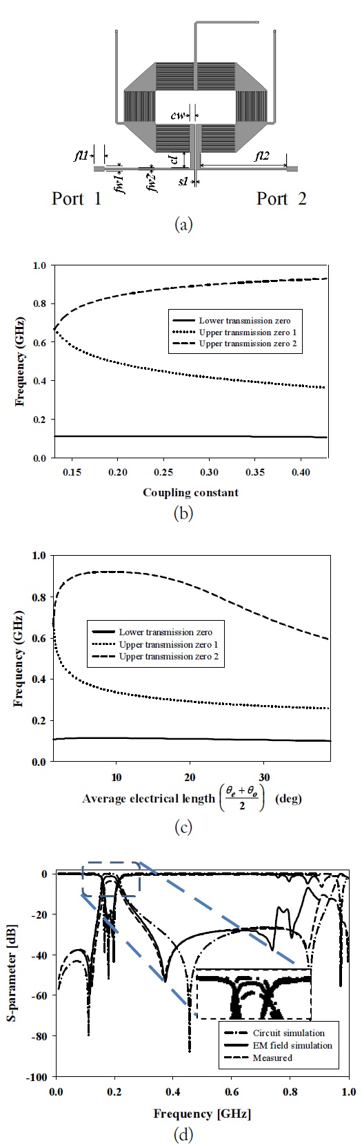
We need an equivalent circuit of a third order in-line coupling BPF, as shown in Fig. 1(a), comprising shunt resonators and inductive coupling elements.
The resonators are replaced by the CRLH ZORs in Fig. 1(b) as the first step to form an MTM. The circuit model in Fig. 1(c) results in the frequency response by controlling the elements of Fig. 1(b).
Use of the calculation in [6] results in the circuit elements for the ZOR at 175MHz as follows:
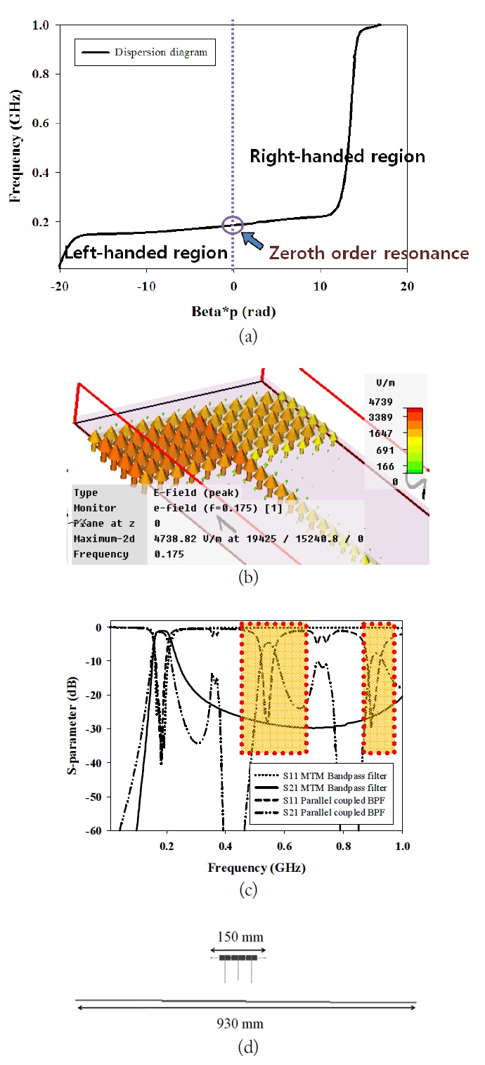
The frequency response and the MTM properties of the ZORs can be presented using a dispersion diagram and electric field distribution with the geometrical information of
Fig. 2(a) shows that the ZOR is obtained at 175MHz. Namely, the propagation constant (
[Table 1.] Specifications of the bandpass filter
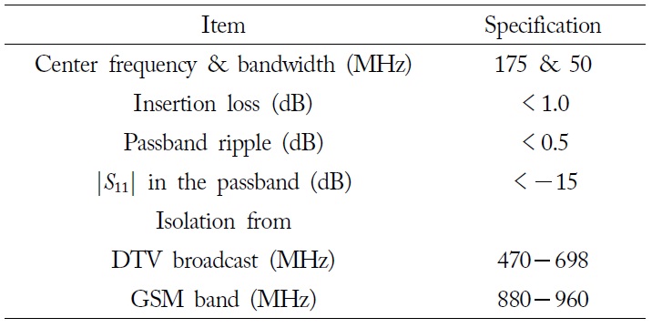
Specifications of the bandpass filter
The proposed SLC MTM ZOR BPF is shown in Fig. 3(a), with g
Both the measurement and the EM simulation have good results for the insertion loss as well as the return loss in Fig. 3(d) when compared to other distributed element filters (the EM simulated and measured insertion losses are less than 1 dB and 3 dB, respectively, with a lossy and cheap dielectric FR4).
A novel compact SLC microstrip ZOR BPF has been proposed for a VHF-band operation with stopband improvement by changing the in-line configuration. The equivalent circuit for the initial configuration has been set up to generate a passband centered at 175MHz with CRLH ZORs coupled through inductive line segments. This short filter is folded to let the source couple to the load, which results in TZs that improve the skirt-slope and stopband with attenuation higher than 30 dB and provide a further size-reduction rate reaching 80%. The simulation and experimental performances meet the requirement for enhanced stopband isolation as a very small filter.