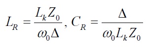
There has been intense research on metamaterial (MTM)-based transmission lines. The structure and theory of onedimensional (1D) composite right- and left-handed transmission lines (CRLH-TLs) have been studied and analyzed a great deal [1-4]. The conventional transmission lines, which support transverse electromagnetic waves and follow the right-hand rule, have been characterized by the distributed series inductance
In this paper, despite the lossy substrate (FR4), a BPF with a compact size and low-insertion loss is proposed. Although the proposed BPF has a narrow fractional bandwidth, a wide tunable range of the center frequency can be obtained by varying the center frequency independently. Furthermore, the proposed tunable BPF has only one DC bias to control the center frequency. The presented tunable filter is for applications in the ISM band (400 MHz) and LTE band (800 MHz), but may easily be modified for other applications using different bands.
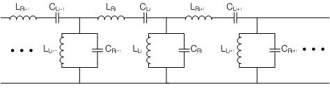
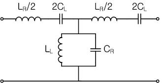
Fig. 1 shows that the conventional CRLH-TL has a periodic structure with multiple cells. Fig. 2 shows one cell of the conventional CRLH-TL in the form of a T-symmetric equivalent circuit.
The source resistance of
L = R0L,
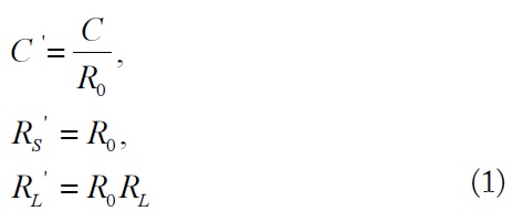
where
If
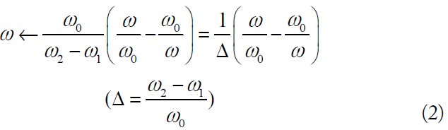
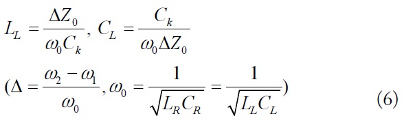
where Δ is the fractional bandwidth of the passband.
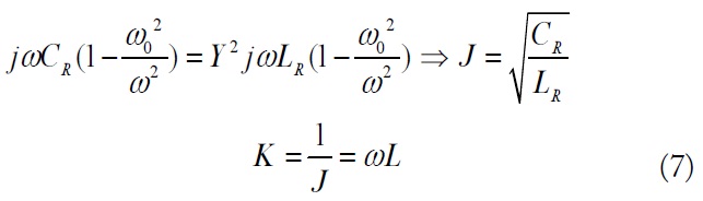
The new filter elements are determined using (2) in the expressions for the series reactance and shunt susceptance. Thus,
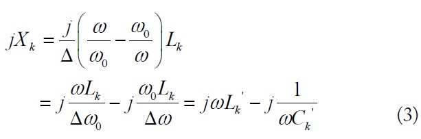
which shows that a series inductor given in the low-pass prototype,
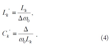
In the same manner, a shunt capacitor given in the lowpass prototype,
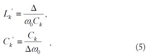
When the center frequency is 0.8 GHz, the values of the inductors and capacitors (
where
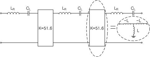
Fig. 3 shows an equivalent circuit using inverters of Fig. 2. In it, lumped inductors can be used instead of impedance inverters. The use of lumped elements saves space and lowers the fabrication cost. By using inverters, an identical series tuned resonator can be substituted for the parallel resonant circuit section of the BPF. Therefore, all of the varactors are controlled by the same voltage. The value of the
where,
Ⅲ. DESIGN OF THE CRLH TYPE TUNABLE BPF
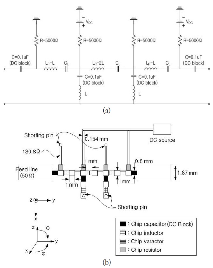
Fig. 4(a) shows the circuit of the proposed CRLH-TL type tunable BPF using the lumped-inverters and DC biases. Fig. 4(b) shows the geometry of the proposed CRLH-TL type tunable BPF. It is constructed using microstrip lines on an FR-4 substrate (with a relative permittivity of 4.6 and a height of 1 mm). The circuit was built with lumped-elements and varactors, resulting in a compact size. The two inverters, a series capacitor, and a series inductor are substituted for the parallel resonant circuit at the T-equivalent circuit of one CRLH-TL cell. After the substitution, all of the series capacitors are replaced with the varactors, and the inverters are replaced with lumped elements. Therefore, the center frequency of the BPF is controlled by varactors of the same value.
The simulation software used in this paper is CST STUDIO SUITE (Computer Simulation Technology AG, Darmstadt, Germany). The design frequency is 0.8 GHz. The diameter of the via hole is 0.5 mm. The size of the BPF is approximately 15 mm×5 mm, neglecting the feed and DC lines. The impedances of the feed and DC lines are 50 Ω and 130.8 Ω, respectively. The width of the feed line is 1.87 mm. The other dimensions are depicted in Fig. 4(b). To provide a DC block to the shunt inductors and the feed lines, four chip capacitors (0.1 μF) were put into the structure, as shown in Fig. 4.
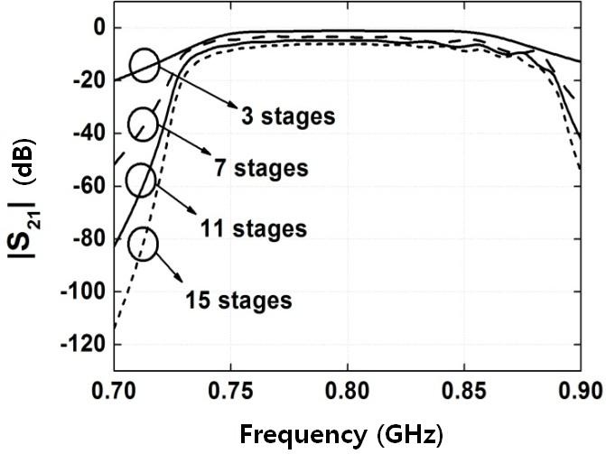
Fig. 5 shows the simulated insertion loss variation graph versus the number of stages at 0.8 GHz. The slope of the stopband attenuation can be made steeper by increasing the number of cells. However, the insertion loss inside the passband can be larger.
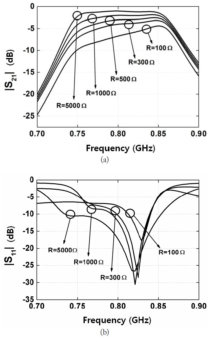
Fig. 6 shows the insertion loss and return loss variation versus the value of the resistance at 0.8 GHz. To prevent the radio frequency (RF) signal from flowing into the DC lines, the resistor should be much larger than 50 Ω. Therefore, 5 kΩ chip resistors were used to give the proper DC voltage to the chip varactors. A large resistance value reduces the insertion loss at the expense of the total circuit size, especially when it is made as a monolithic microwave integrated circuit. The used varactor is the SMV1265-011LF hyper-abrupt junction varactor diode from Skyworks Solution Inc. to control the center frequency-C(Vbias=0V) =22.47 pF, C(Vbias =5 V) =3.38 pF, C(Vbias =7 V) =1.86 pF, C(Vbias =14 V) =1.05 pF, C(Vbias =26 V) =0.73 pF, and C(Vbias =30 V) =0.71 pF. The series resistance in the varactor is 2.4 Ω.
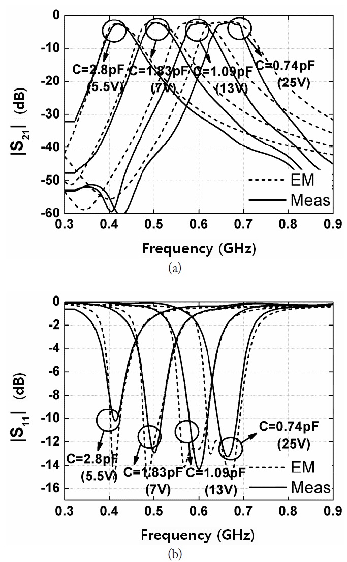
Fig. 7 shows the comparison between the EM-simulated and measured
[Table 1.] Summary of center frequency (f0) and bandwidth versus the varactor values (C)
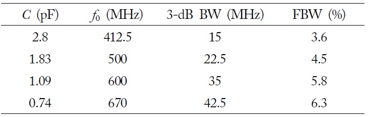
Summary of center frequency (f0) and bandwidth versus the varactor values (C)
[Table 2.] Comparison between the proposed filter and conventional ones
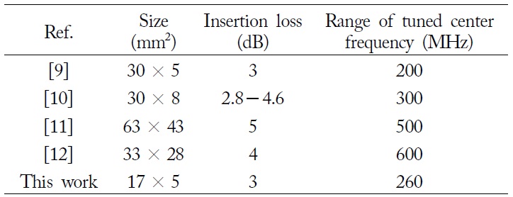
Comparison between the proposed filter and conventional ones
Table 1 shows the summary of the center frequency, 3-dB BW, and FBW versus the chip varactor values.
Table 2 shows the comparison between the proposed filter and the conventional ones in terms of size, insertion loss, and a tunable range of the center frequency.
A tunable BPF based on the varactor-loaded MTM line is proposed, and the detailed theory concerning its operation is discussed. By using inverters, series-tuned resonators are substituted for the parallel resonant circuit section of the BPF. All of the varactors that are substituted for the capacitors are controlled by the same voltage of one DC bias. Therefore, the center frequency of the BPF is controlled by varactors of the same value. In addition, lumped elements replaced the inverters to save space and to lower the fabrication cost. Considering that the FBW is maintained between 4.5%?6%, the tunable range of the center frequency is around 170 MHz. Otherwise, the tunable range of the center frequency is around 260 MHz. The results of the EM-simulation and the measurements show good agreement. The circuit size was compact (17 mm×5 mm), since only lumped elements were used to design the device. The insertion loss of the proposed BPF is less than 3 dB, despite the high loss of the FR4 substrate, and the return loss is more than 10 dB in the passband.