During the electrorefining of used metal nuclear fuel, active metal fission products such as Group I, Group II, and lanthanides are oxidized into chlorides and partitioned into a molten chloride salt electrolyte, LiCl-KCl eutectic [1]. Since the fission products involved in the molten salt electrolyte are highly radioactive and heat-generating, they can modify the physical and chemical properties of the molten salt electrolyte by increasing the melting temperature or contaminating the extraction cathode with fission products [2]. These changes make it difficult to function as a normal electrolyte during the electrochemical process. Therefore, after a certain time the eutectic molten salt electrolyte must be replaced with a fresh salt, where the spent molten salt electrolyte is referred to as waste salt. Because the LiCl- KCl eutectic waste salt generated from the electrorefining of used metal nuclear fuel contains fission products including high heat generating 137Cs and 90Sr, it must be disposed of in durable waste forms that will remain stable in the environment of a geologic repository for thousands of years. Thus, it is very relevant to fission product removal to focus on reducing the final waste amount caused by waste salt.
Various fission product separation processes such as the dry method are being researched using LiCl-KCl eutectic molten salt: oxide [3,4] or phosphate [5,6] precipitation and ion-exchange by zeolite column [7]. Among these technologies, only the ion-exchange process can separate all fission products from a LiCl-KCl eutectic salt [8]. The precipitation process can only separate lanthanides, since Group I and II fission products are not converted into molten salt-insoluble oxides or phosphates [9].
As an alternative to ion-exchange, a zone freezing process can be applied. This is a kind of melt crystallization process, which is principally similar to a vertical Bridgman method [8,9]. The operation principle of this process is the solubility difference of the impurities between the solid (that is, crystal) and melt phase. Here, impurities prefer to remain in the melt phase, not in the crystal phase. The zone freezing process introduced in this research for waste salt purification, that is, fission product separation, has some different aspects compared to a conventional vertical Bridgman method: it does not use any seed, and therefore does not use a tapered, sharp point formed at the closed end of the crucible, and the crystal is grown in the downward direction. The operating concept of the zone freezing process for the purification of eutectic salt waste is as follows: first, after an entire melting, the hot crucible containing molten salt and impurities is slowly moved toward a cold zone. As the molten salt is crystallized, impurities are concentrated in the melt phase, not in the solid (crystal) phase. Finally, when the molten salt is entirely crystallized, the impurities are concentrated at the bottom part of the product crystal.
As mentioned, eutectic waste salt from electrorefining of spent metal fuel contains mainly Group I (Cs, Rb), Group II (Ba, Sr), and lanthanide (Y, La, Ce, Pr, Nd, Pm, Sm, Su, Gd, Tb and Dy) fission products, where the weight fractions of each fission product in the metal fuel for a fast reactor are 3.30, 1.55, and 7.78 wt%, respectively [7]. Since the content of lanthanides is nearly twice that of Cs and Sr, if the lanthanides are separated from the eutectic waste salt in advance, a more efficient operation of the zone freezing process is possible than when treating all of the fission products at once. Based on the above consideration, we introduced a sequential separation process composed of an oxygen sparging process for separating lanthanides and a zone freezing process for separating Group I and II fission products.
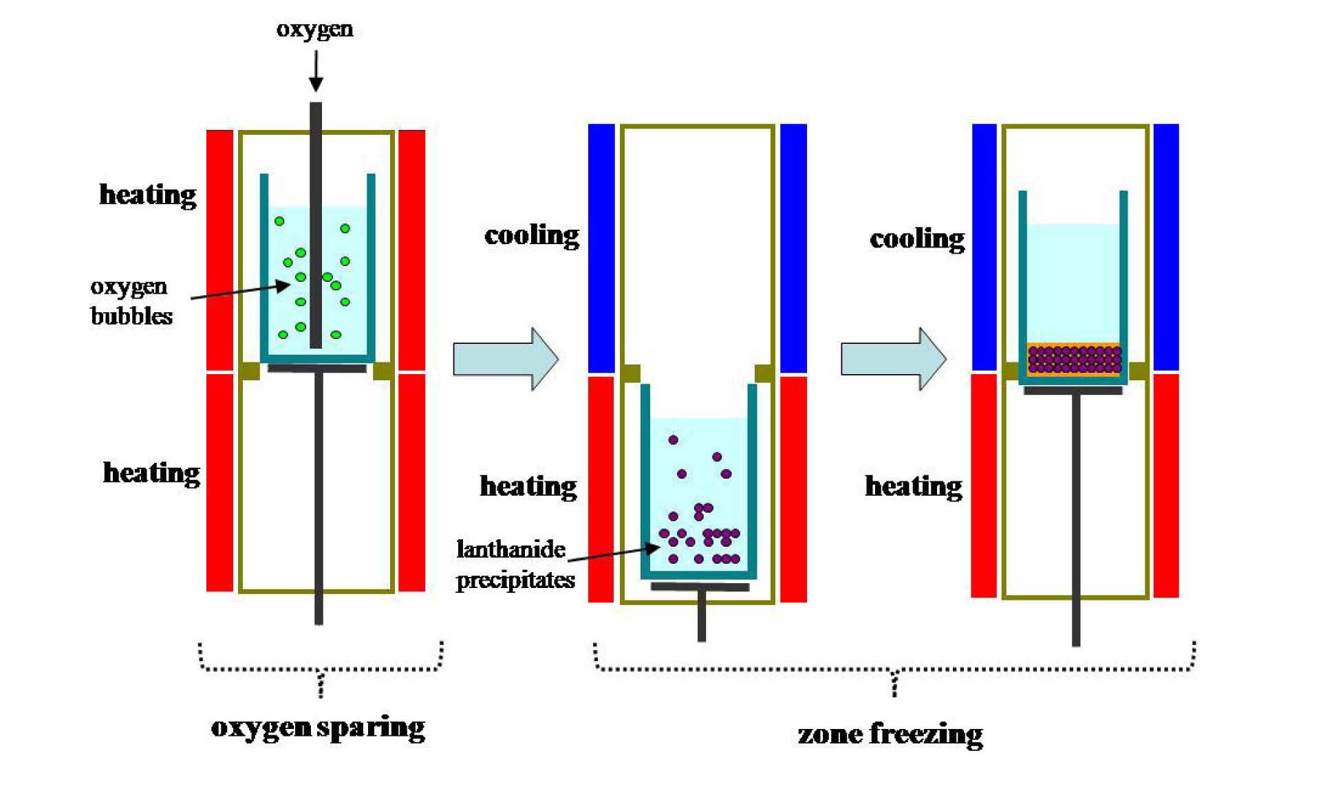
Fig. 1 explains the concept of the sequential separation process. The first step of the sequential separation is an oxygen sparging process. In this process, nearly all lanthanide elements are converted into salt insoluble oxides or oxychlorides. However, Cs and Sr are not oxidized. The second step is zone freezing. In this process, both the precipitation of lanthanide precipitates (oxides or oxychlorides) and the concentration of Cs and Sr are performed. Finally, after these two steps, eutectic salt waste is separated into two layers: upper pure salt and lower mixture. In the lower mixture layer, lanthanide precipitates (oxides or oxychlorides) and most Cs and Sr are found in addition to eutectic salt residue. After the sequential separation process, the lower mixture layer is separated from the pure salt layer, where the pure salt layer can be reused and the mixture layer can be treated to fabricate a durable waste form or separate eutectic salt residue using additional processes such as distillation. In this study, performance tests on the
sequential separation process, composed of an oxygen sparging process for separating lanthanides and a zone freezing process for separating Group I and II fission products, were carried out with a surrogate eutectic waste salt.
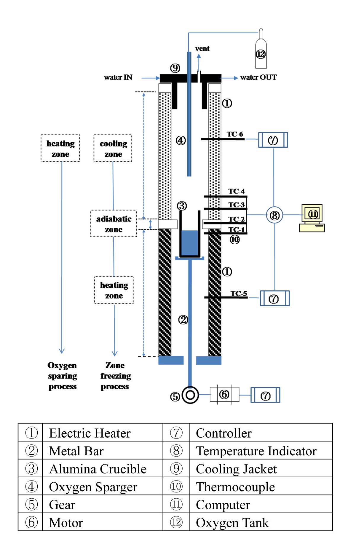
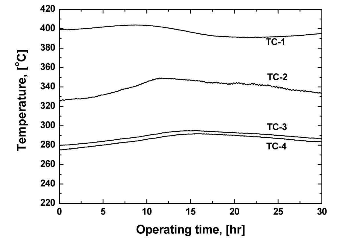
Fig. 2 shows a schematic diagram of the experimental apparatus for the sequential separation process using both oxygen sparging and zone freezing processes, sequentially, for separating both lanthanides and Group I/II chlorides. It consists of a furnace chamber, a device to ascend and descend an alumina crucible, and a top flange for oxygen sparging. When operating the zone freezing process, the furnace chamber is divided into three zones based on the axial temperature distribution: heating (bottom part), adiabatic (middle part), and cooling (top part). The latent heat of crystallization evolving as the crystal grows has to be effectively removed. Thus, to effectively eliminate the latent heat during crystallization, a cooling jacket using water was installed. Using the cooling jacket, the latent heat generated during crystallization can be effectively removed. Six thermocouples were mounted vertically to control operating temperature (TC-5 and TC-6) and to detect the temperature change of each part during crystallization (TC-1, TC-2, TC-3 and TC-4). Fig. 3 shows a typical example of the axial temperature change of each part. The temperature change of the cooling (TC-3 and TC-4) and heating (TC-1) zone ranged about 275-295 ℃ and 395-405 ℃, respectively. The temperature of the adiabatic zone (TC-2), the starting point of the crystallization of the melt, ranged from about 325 to 350 ℃. The vertical distance between the temperature detecting points was 0.025 m.
The regulation of the heating zone temperature were of great importance in the zone freezing process. Therefore, the heating zone was well sealed with ceramic fibers to minimize the heat loss and the kanthal wire used as the heating element was controlled using a programmable
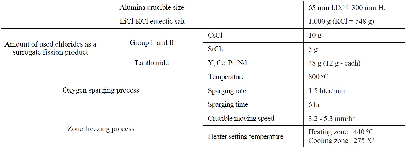
[Table 1.] Detailed Experimental Conditions

Detailed Experimental Conditions
PID temperature controller (UP351) with an accuracy of 0.1 %. An alumina crucible was used because of its low thermal conductivity (0.004 cal/cm·sec·℃), fairly good thermal shock resistance, and relatively high working temperature (1,900℃). In the zone freezing process, the crucible moving speed is a very important operating factor since the crucible moving speed determines the cooling rate; therefore it determines the crystal growing rate. To control the crucible moving speed, the zone freezing apparatus is equipped with a motor and a speed reduction gear. By controlling the motor’s RPM, the crucible moving speed was controlled. The crucible moving speed ranged from 3.2 to 5.3 mm/hr.
In the oxygen sparing process, oxygen is sparged into a molten salt bed through a vertical tantalum sparger which has several 1mm I.D. holes around the bottom sparging point with a 1.5 liter/min sparging rate in all experiment conditions. The oxygen sparging process was performed at the upper-part of the furnace chamber. Table 1 summarizes the detailed experimental conditions.
As representatives of the lanthanide and Group I/II fission products involved in salt waste, four anhydrous lanthanide chlorides (Ce, Pr, Y, and Nd, Alfa Aesar, 99% purity) and Cs and Sr (Sigma-Aldrich, 99.99+%) were used. As for eutectic salts, 1,000g of a LiCl-KCl solid salt with a purity of 99.9 % (KCl : 54.8 wt.%, eutectic point: 352 ℃) was used. An alumina crucible of 65 mm in inner diameter and 300 mm in height was used. The experimental procedure of the sequential separation process for separating both Group I/II and lanthanide fission products is as follows.
1) Using the crucible rising device, the alumina crucible containing the eutectic salt mixture is positioned at the upper part of the furnace chamber.
2) The upper part of the chamber is heated and the oxygen sparging process for lanthanide precipitation is performed. During the oxygen sparging process, the lower part of the furnace chamber is turned off.
3) When the oxygen sparging process is finished, the alumina crucible is descended to the bottom. At this time, the temperature of the upper (cooling zone) and lower (heating zone) parts of the furnace chamber are set to the wanted temperature.
4) When each part of the chamber reaches its desire temperature, the crucible is ascended to the cooling zone at a constant moving speed. After full cooling (or crystallization) of the salt mixture, the salt ingot (or cooled salt) is removed from the alumina crucible and sliced into several parts axially from the top, where the last part is the precipitate phase. The sliced parts are weighed and dissolved in distilled water, and the cesium, strontium, and lanthanides concentrations of each part are then analyzed using inductively coupled plasma-atomic emission spectrometry (ICP-AES, Perkin Elmer, Optima 4300DV).
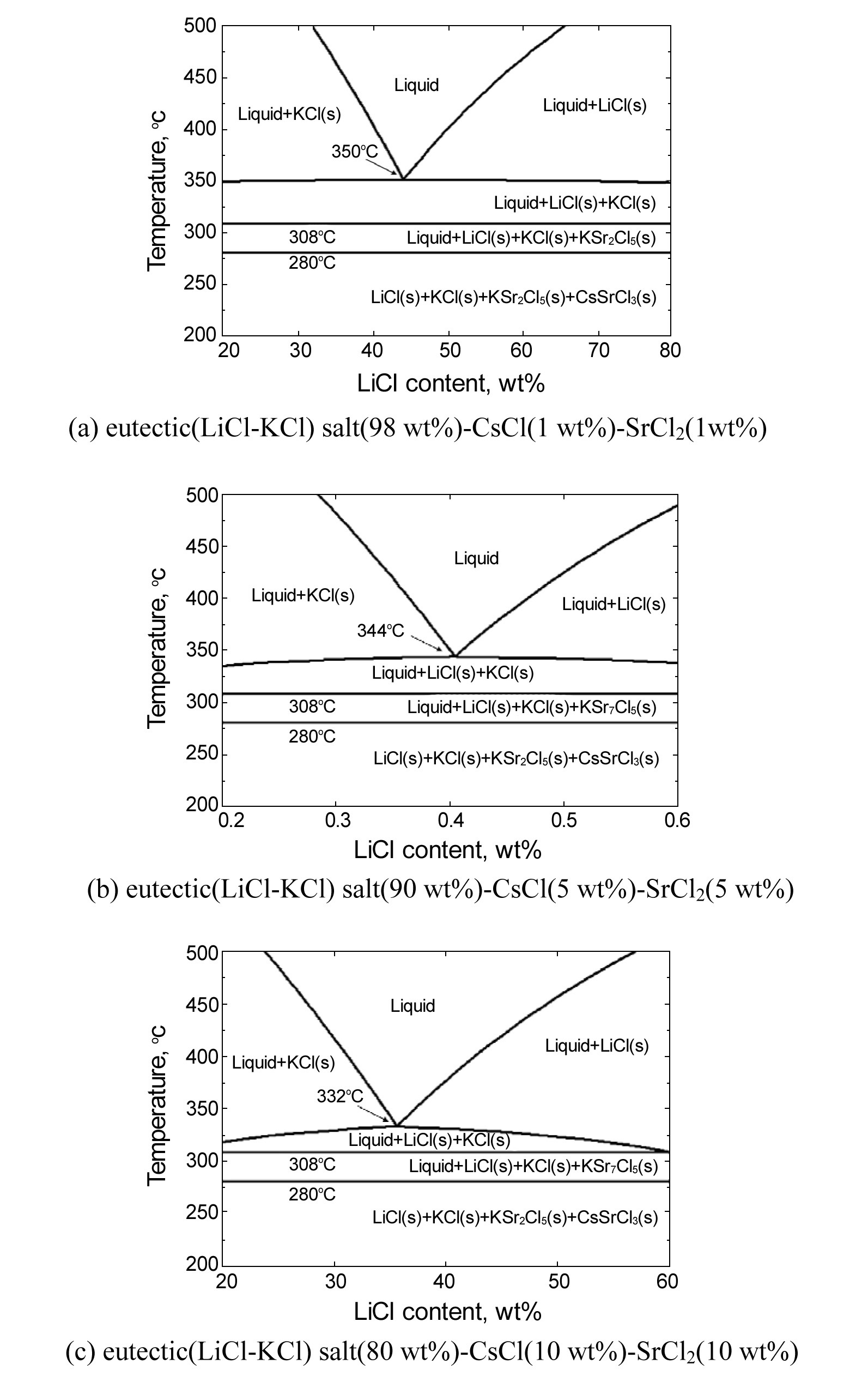
When crystallization is used to separate a component from a mixture, a temperature-composition phase diagram is important with regard to the applicability of crystallization [12]. A solid-liquid phase diagram represents the relationship between composition and temperature, and crystallization can be used when the phase diagram of the target system is of a eutectic type rather than a solid solution type. Fig. 4 shows a temperature-composition phase diagram for a eutectic salt(LiCl-KCl)-CsCl-SrCl2 system drawn using FactSage software [13]. As shown, under the condition of a constant composition, with a decreasing temperature, the phase and type of the components are changed. For example, in the case of 1 wt% SrCl2 and CsCl and 98 wt% eutectic (LiCl(45.2 wt%)-KCl), when the temperature is over 350 ℃, all components are present as a liquid phase (LiCl-KCl, CsCl and SrCl2), but with a decreasing temperature until about 308 ℃, LiCl and KCl are present as a solid phase, while the others are present as a liquid phase. Further decreasing the temperature, a new solid compound, KSr2Cl5, is formed in the range of 280 - 308 ℃ in addition to solid LiCl and KCl. Below 280 ℃, in addition to solid LiCl , KCl and KSr2Cl5, solid CsSrCl3 is formed (Fig. 4(a)). Similar results can be seen in the case of 5 wt% CsCl / SrCl2 - 90 wt% eutectic salt (Fig. 4(b)) and 10 wt% CsCl/ SrCl2 - 80 wt% eutectic salt (Fig. 4(c)). Thus, if eutectic molten salts containing CsCl and SrCl2 are cooled, i.e. crystallized at a temperature above about 310 ℃, only LiCl and KCl are present as a solid, and CsCl and SrCl2 exist as a liquid phase. Therefore, if eutectic waste salt containing CsCl and SrCl2 is cooled (or crystallized) at a temperature above 308 ℃, only LiCl and KCl are present as a solid, and CsCl and SrCl2 are present as a liquid phase. Consequently, it is proposed that eutectic waste salt containing cesium and strontium can be purified by a zone freezing process.
When an impurity is thoroughly mixed in a liquid melt and the diffusion of the impurity is negligible in crystal, the impurity distribution in the zone freezing process is represented by an impurity segregation coefficient,
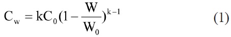
Eq. (1) can be described as Eq. (2)
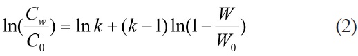
where C0 is the initial impurity concentration in a liquid (or melt) before crystal formation, W is the weight of the sliced crystal from the top of a salt ingot, W0 is the total crystal weight and CW is the impurity concentration at W. An impurity segregation coefficient close to 1 means that no impurity concentration occurs, while a value close to 0 means an almost perfect concentration of impurity in a very small part of the crystal ingot.
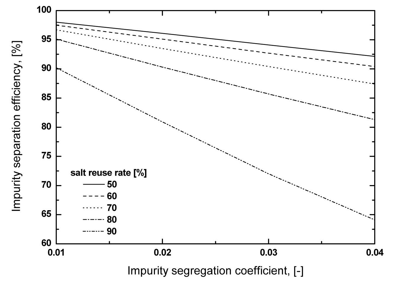
In a zone freezing process, the impurity separation efficiency is a function of both the impurity segregation coefficient,

means salt reuse rate.

As shown in Fig. 5, the impurity separation efficiency decreases with increasing
salt waste amount, but as shown in Fig. 5, a high salt reuse rate, in constant
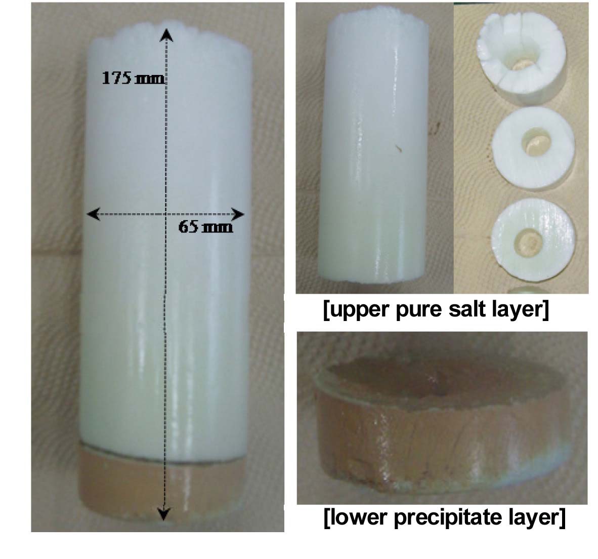
Fig. 6 shows the final cooled salt ingot after the sequential separation process. As shown it had a cylindrical hole along the center line in the upper pure salt layer and showed clear layer separation: upper pure salt layer, lower precipitate layer. The lower precipitate layer had no cylindrical hole. The weight of the precipitate layer was about 15 - 20% of the cooled salt ingot weight. The cooled salt ingot was sliced into several parts axially from the top, where the last part was the precipitate layer
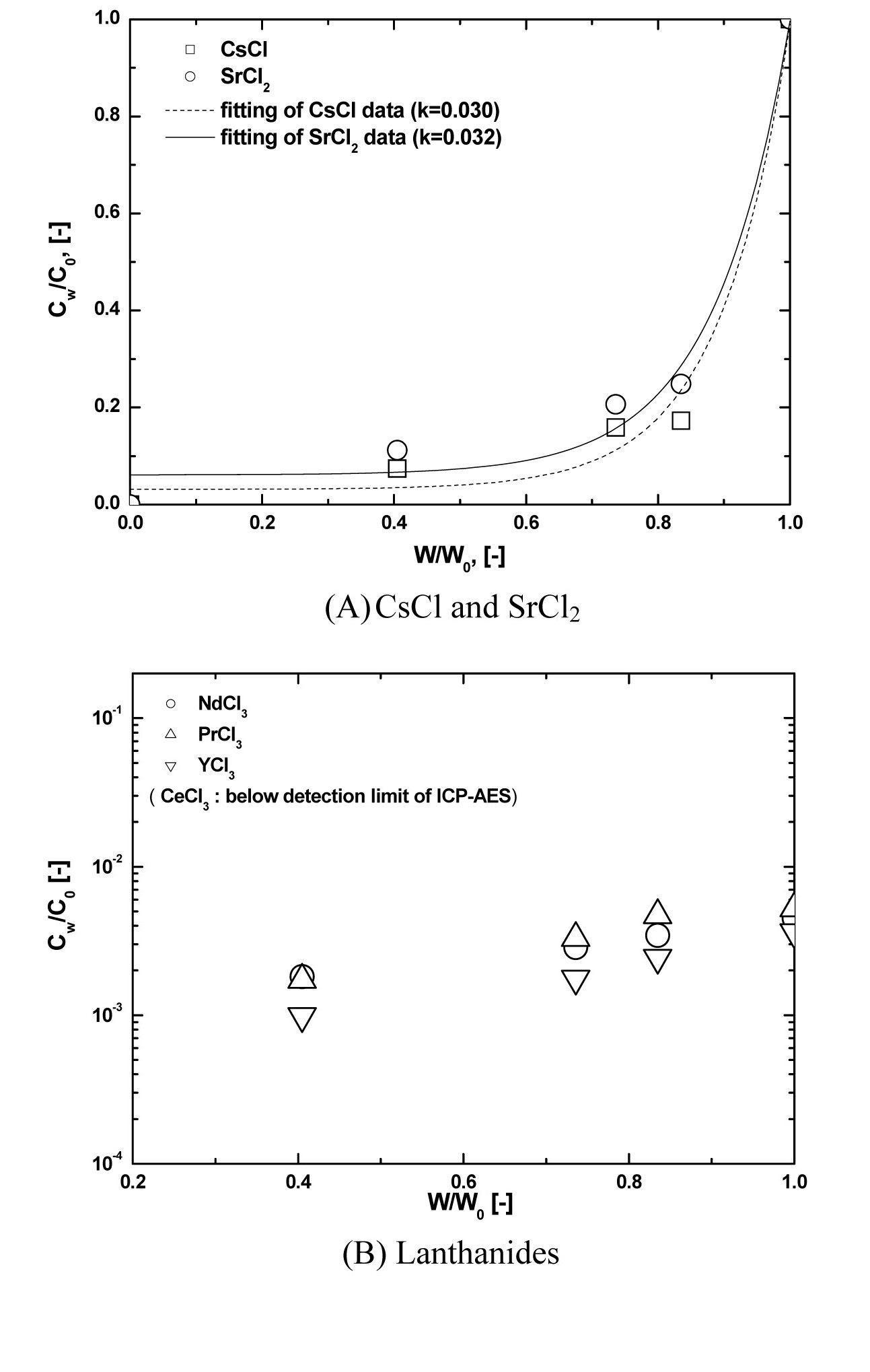
Fig. 7 shows examples of the axial concentration distribution of Cs, Sr (Fig. 7(A)) and lanthanide chlorides (Fig. 7(B)) under the conditions of a 3mm/hr crucible moving speed and 800 ℃ of oxygen sparging temperature. As shown in Fig. 7(A), the impurity segregation coefficients of Cs and Sr are 0.030 and 0.032, respectively, as induced by adopting Eq. (1). To evaluate the k value, the Levenberg-Marquardt method [14], the most widely used non-linear curve fitting method, was used. In all axial directions of lanthanides, CW/C0 did not exceed about 0.005, and was even below the detection limit of ICP-AES, below 0.5 ppm, in the case of CeCl3. Having a CW/C0 of lanthanides below 0.005 means over a 99.5 % separation efficiency. Cho et al. [4,6] reported that the lanthanide chlorides involved
in LiCl-KCl eutectic salt, under the 800 ℃ condition, had over 99 % conversion efficiency into the eutectic saltinsoluble precipitates, oxides or oxychlorides, by the oxygen sparing process and proposed the reaction equations between
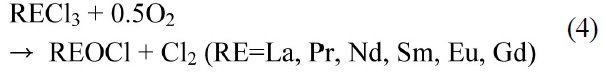


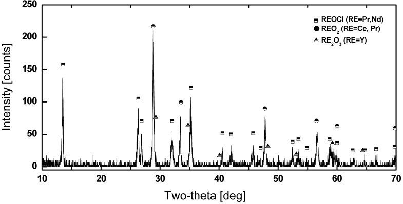
From these results, in the case of the lanthanides, by a reaction with oxygen at 800 ℃, over 99.5 % of the lanthanides are converted into molten salt?insoluble precipitates, oxides, or oxychlorides. Fig.8 shows the XRD pattern of the lanthanide precipitates formed by reaction with oxygen.
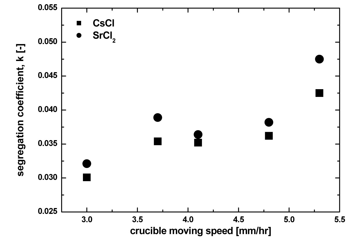
Fig. 9 shows the effect of crucible moving speed on the segregation coefficient of Cs and Sr. With increasing crucible moving speed, the separation efficiency of Cs and Sr, the k value, was increased. As was previously mentioned, the crucible moving speed means the cooling rate, that is, the crystal growth rate. Therefore, it is clear that to obtain
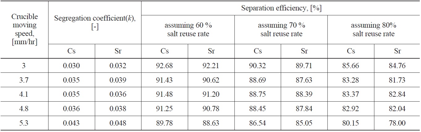
Separation Efficiency of Cs and Sr with Experimentally Obtained Segregation Coefficient(k) in the Sequential Separation Process
a small k value, i.e. to obtain high Cs and Sr separation efficiency, the crucible moving speed must be as low as possible. In this case, however, the operating time to obtain the final product crystal as well as the high separation efficiency would be too long. Therefore, in a zone freezing process, the choice of optimum crucible moving speed considering the operating time and separation efficiency is very important. In this study, in the range of a 3.7 - 4.8 mm/hr crucible moving speed, there was little effect of crucible moving speed on the segregation coefficient. The calculated separation efficiencies of Cs and Sr with salt reuse rate assumed are listed in Table 2. When assuming a 60% eutectic salt reuse rate, except for over a 0.04 segregation coefficient value, over a 90% separation efficiency is possible, but with increasing eutectic salt reuse rate to 80%, about a 82 - 86 % separation efficiency was estimated.
The performance test of the sequential separation process composed of oxygen sparging and a zone freezing process was carried out. The first step of the sequential separation is an oxygen sparging process, where nearly all lanthanide elements are converted into salt insoluble oxides or oxychlorides. However, Cs and Sr are not oxidized. The second step is zone freezing. In this process, both the precipitation of lanthanide precipitates (oxides or oxychlorides) and the concentration of Cs and Sr are performed. Experiments were carried out with 1 kg of a LiCl-KCl solid salt and four anhydrous lanthanide chlorides (Ce, Pr, Y, Nd) plus Cs and Sr, which were used as representatives of the lanthanide and Group I/II fission products involved in eutectic salt waste. Based on a solid-liquid phase diagram, it was estimated that eutectic waste salt containing Cs and Sr could be purified by a zone freezing process. In case of the lanthanides, by a reaction with oxygen at 800 ℃ over 99.5 % of lanthanides were converted into molten salt ?insoluble precipitates, oxides, or oxychlorides, but Group I and II fission products were not converted into molten salt-insoluble precipitates by reaction with oxygen. In a zone freezing process for separating Cs and Sr, the separation efficiency of Cs and Sr increased with a decrease in crucible moving speed. In this study, in the range of a 3.7 - 4.8 mm/hr, there was little effect of crucible moving speed on the separation efficiency of Cs and Sr. Therefore, when considering operating time, a 3.7 - 4.8 mm/hr crucible moving speed is a proper speed in the zone freezing process. When assuming a 60% eutectic salt reuse rate, a separation efficiency of over 90% is possible, but by increasing the eutectic salt reuse rate to 80%, a separation efficiency of about 82 - 86 % was estimated. The sequential separation process for treating eutectic waste salt generated from an electrorefining of used metal fuel can be one solution that can minimize the amount of final waste form needed to dispose of the pyroprocessing of used fuel.