The most effective option for a nuclear fuel cycle should generally be selected in consideration of the political, economic, and social aspects of the particular country [1]. Since the nuclear accident in Fukushima, Japan, greater emphasis has been placed on the back-end nuclear fuel cycle. At present, every country that uses nuclear energy has attempted to induce a nuclear fuel cycle that is most appropriate to that country [2], and has expressed concerns on the management of spent fuel [3]. Hence, it is very important to develop a software tool that can enable nuclear fuel cycle analysts to analyze the material flow of the nuclear fuel cycle and its economy [4].
Under these circumstances, the Korea Atomic Energy Research Institute has developed professional software for a nuclear fuel cycle analysis that can aid in inducing the optimum nuclear fuel cycle. This software was given the code name, FUTURE.
The aim of this paper is to provide useful information on the development of a nuclear fuel cycle analysis code for nuclear fuel cycle researchers of each country that uses nuclear energy, by presenting the function of the FUTURE code and a calculation algorithm.
Generally, when the entire nuclear fuel cycle is observed, the processing stage of the nuclear fuel cycle starts with the mining of uranium. Hence, in a time dependent dynamic model that takes the time concept into consideration, to know the quantity of uranium, which will be necessary in the future, is necessary to predict the amount of electric demand [5].
The nuclear fuel cycle analysis code, called FUTURE, is a software that can be used to design and analyze the processing stage of the nuclear fuel cycle easily by considering the entire nuclear fuel cycle from the prediction of the quantity of the electric demands to the disposal of the spent fuel, which has the virtue of enabling a small number of professional research personnel to carry out a nuclear fuel cycle analysis.
This software is a research support tool that can be used to evaluate the material flow of each nuclear fuel cycle and its economy by comparing the calculation results with the scenario, and to solve an interface problem that might occur among researchers. With this software, a dynamic simulation is also possible, which allows the setting of a scenario that can be applied separately depending on its technological and economic level to calculate the material flow to which the time concept is applied. Hence, it is possible for a code user to design the front-end and back-end processes of a nuclear fuel cycle process easily and constitute diverse nuclear fuel cycle scenarios by modeling nuclear materials that should be managed through out the entire nuclear fuel cycle. Furthermore, the new code also allows the selection of a part of the processes that are set in the front-end and back-end relationship within a scenario for the simulation and detailed monitoring of the material flow to carry out a more precise analysis [6].
The FUTURE code can monitor and store not only the nuclear materials that are input and output by processes from the prediction of the electric demands to the disposal, but also the values of the parameters. For example, the code has a function that allows a user to check the resulting values of a primary simulation before modifying the values of input variables to continue the simulation [7], which enables an analysis of diverse cases that can occur from the point of a nuclear fuel cycle process. In this paper, a detailed material flow algorithm for this kind of nuclear fuel cycle processing stage is presented. High-level programming software used to develop this code includes Microsoft Visual C#, Microsoft Windows Presentation Framework (Library), and Microsoft SQL Server.
The FUTURE code allows a code user to easily change the linkage relationship between processes toward a desirable direction. Accordingly, a researcher can evaluate various nuclear fuel cycle options promptly, as the material flow can be easily grasped through the nuclear fuel cycle processing stage while changing the input data. In other words, the usefulness, flexibility, and user-oriented convenience of the code have been enhanced.
The new code also provides data management functions.
[Table 1.] Comparison of the Nuclear Fuel Cycle Analysis Codes
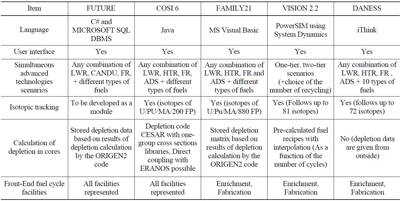
Comparison of the Nuclear Fuel Cycle Analysis Codes
It allows an individual user to independently check the evaluation data from a personal computer, and use such data freely when it is needed using data search functions [8].
For an analysis of the nuclear fuel cycle, the FUTURE code provides functions that can be used to manage the basic master data such as the process information and nuclear material information, material flow and parameter information of the process, and simulation results independently on a user’s computer. It also provides an environment for research cooperation by defining a data model based on a commercial Microsoft SQL database in an integrated storage location, and by sharing the database among multiple users [9], thereby reducing the effort and time required for the research personnel to evaluate a nuclear fuel cycle system. Table 1 shows the comparison of nuclear fuel cycle analysis codes.
The FUTURE code can simulate the nuclear fuel cycle desired by a user promptly, as the modeling method is not as complex as the existing commercial nuclear fuel cycle analysis code, and it can change the nuclear fuel cycle process on the canvas.
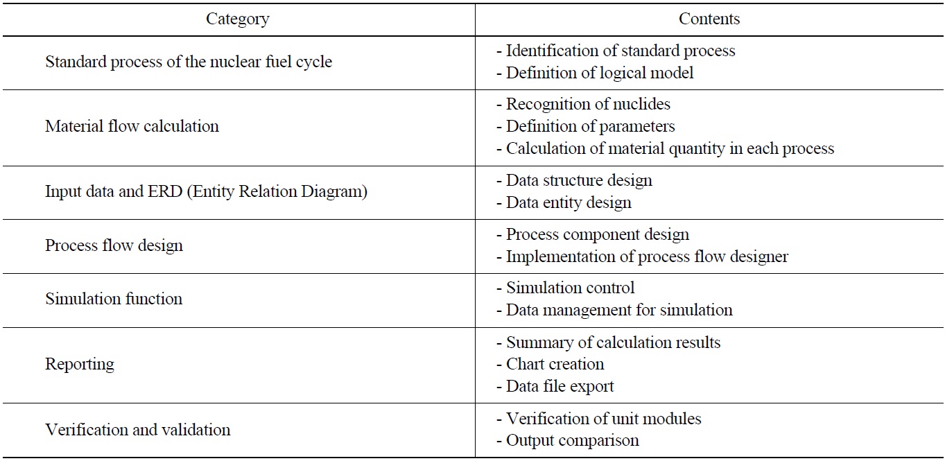
The development of the FUTURE code was implemented in the order of process modeling, data modeling of the nuclear fuel cycle, process flow design by the nuclear fuel cycle, implementation of the simulation function and installation, and verification. Table 2 shows the major works of the code development process for each area.
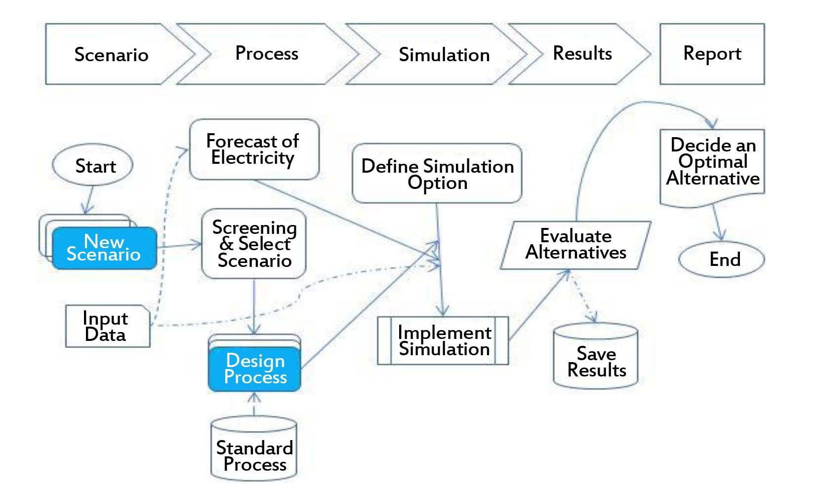
Figure 1 shows the simulation procedure of the nuclear fuel cycle in the form of a flow chart. The simulation can be implemented easily by the program user accessing a menu selection.
[Table 2.] Main Task for FUTURE Code Development

Main Task for FUTURE Code Development
3. UNIT PROCESS DESIGN OF THE NUCLEAR FUEL CYCLE
With the FUTURE code, it is possible to input the parameter values for the entire target period or by year to calculate the flow of nuclear material, which changes based on the processing stage of the nuclear fuel cycle for various scenarios.
It is also possible to analyze the material flow of the entire nuclear fuel cycle using the scenario unit as an assembly of the nuclear fuel cycle process, or to simulate only a part of the process.
The characteristics of the simulation algorithm lie in the fact that it can be implemented reversely from the reactor process to the mining process of uranium based on the electric demand forecast. In the final analysis, with the front-end nuclear fuel cycle, a nuclear material flow can be calculated bi-directionally, including both the forward and reverse directions.
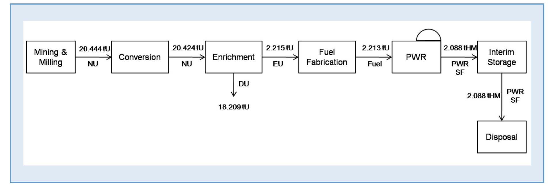
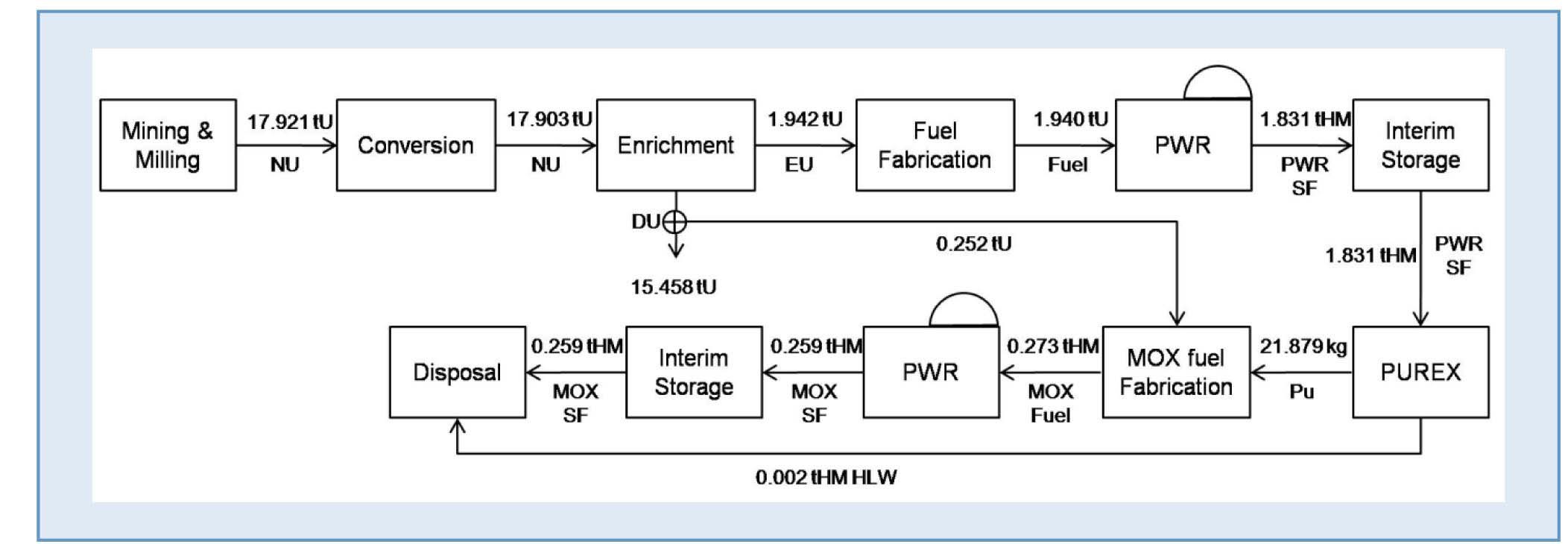
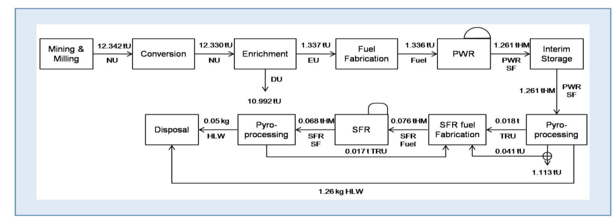
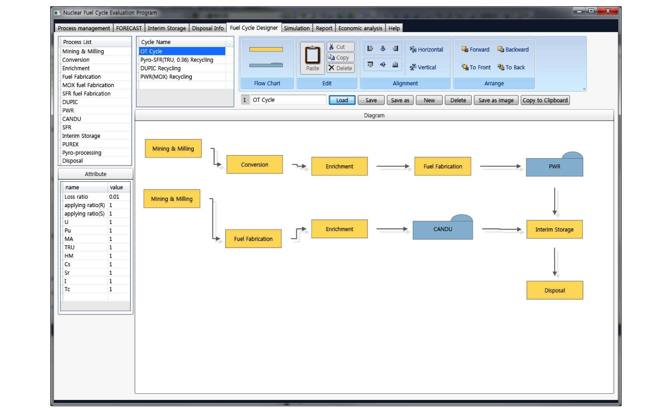
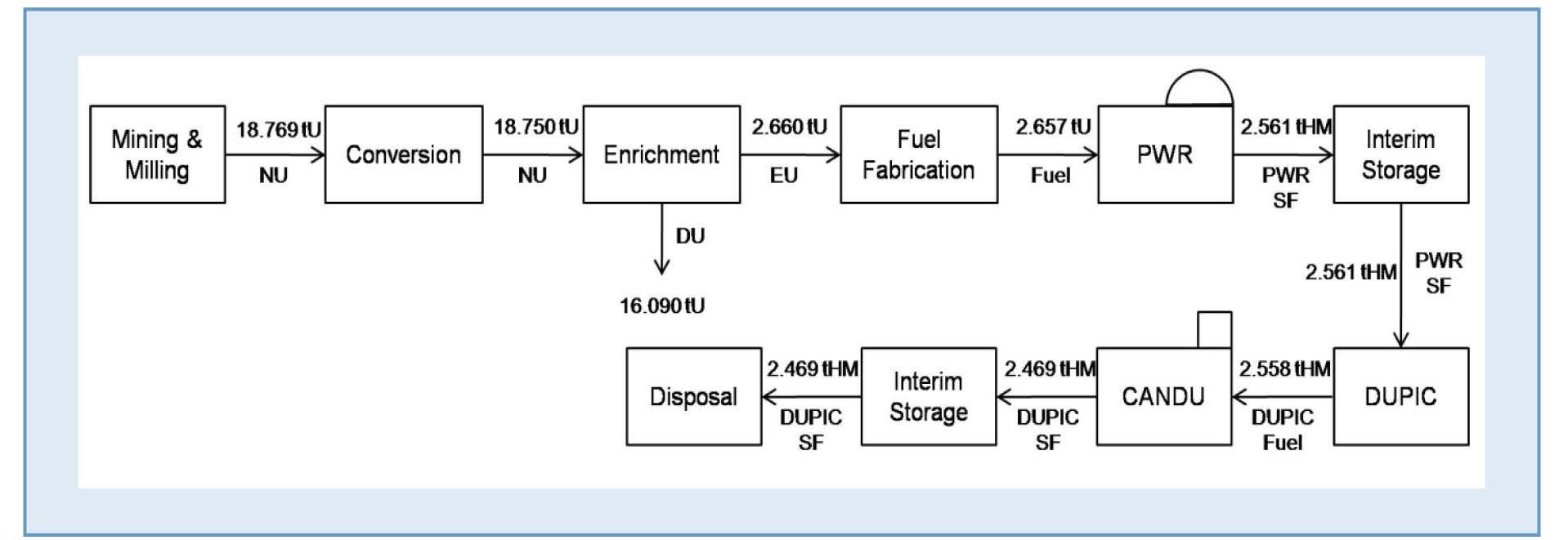
The FUTURE code set has four major scenarios of the predictable nuclear fuel cycle at present (the direct disposal cycle, DUPIC cycle, thermal recycling [PWR-MOX], and Pyro-SFR cycle) as mutually exclusive targets for comparison [10], and maintains the individual process information as basic built-in data. The simulation of the major basic scenarios has a capacity of processing within 30 seconds when the target period is set for 100 years. Figures 2 through 5 show the four types of nuclear fuel cycles [11] that are imbedded in the code.
The FUTURE code maintains the arranged standard processes that can be simulated in the form of components [12].
3.1 Material Flow Calculation of the Nuclear Fuel Cycle
The unit model of a standard process can be divided as shown in Table 3 according to the processing order of the nuclear fuel cycle [13].
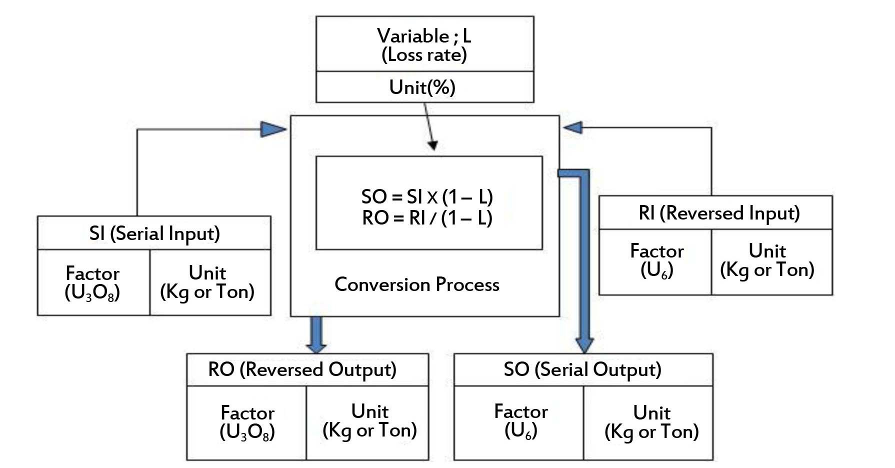
To calculate the quantity of nuclear material that is generated in each process, the process model has divided and defined the material flow inputted and outputted in the PORT (SI: Serial Input, SO: Serial Output, RI: Reverse Input, RO: Reverse Output). The algorithm used for calculating the material flow quantity of the FUTURE code is described in detail in the Appendix.
The code was developed in such a way that a bidirectional simulation is possible to allow the amount of uranium required to be reverse calculated using the quantity of the nuclear fuel that has been calculated from the electric demand forecast. In other words, in the front-end nuclear fuel cycle, it is possible to calculate reversely the flow of nuclear material. As an example, the material flow calculation of the conversion process for a nuclear fuel cycle is shown in Figure 6.
3.2 Specific Functions of the Program Unit Module
3.2.1 Standard Information
For the management of standard processes in the nuclear fuel cycle, each process of mining, conversion, enrichment, fabrication, reactor processes, interim storage, reprocessing, and disposal are managed as standard information.
[Table 3.] Standard Process in the Nuclear Fuel Cycle
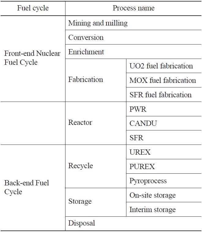
Standard Process in the Nuclear Fuel Cycle
3.2.2 Quantity of Electric Demand Forecast
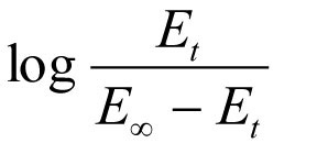
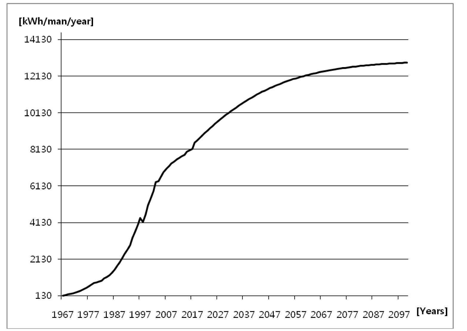
For an electric demand forecast by year, the quantity of electric demand can be predicted by setting the target year of the analysis and inputting the values of the capacity of the reactor (Ministry of Knowledge Economy, 2010). The logistic function for the quantity of electric demand forecast per person is as shown in Equation (1), and forecast examples are as shown in Figure 7. The electricity demand means the amount of electricity being consumed at any given time. It rises and falls in response to a number of things, including the time and environmental factors such as economic growth rate.
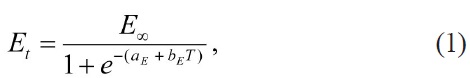
where
E∞= asymptotic limit for the demand E
T = time in years since the base year
aE and bE = parameters estimated by the regression
aE + bE T =
Finally, the FUTURE code enables the calculation of the amount of uranium required using the quantity of electric demand, and thus enables the calculation of the nuclear material flow in the nuclear fuel cycle processing stage from the mining of the uranium to its disposal. Variables
that are used in the calculation can be stored in the database using a save function, for use in the next analysis work. For example, data for the evaluation of economy usually includes the standard unit cost, price index, and interest rate [14].
3.2.3 Management of Scenario Information
A scenario information management module has three main functions. First, it manages information on the nuclear fuel cycle that is deemed technically feasible at present time or in the future. Second, it manages information on process lists that constitute each scenario. This information is automatically updated based on the modeling results of the process flow designer. Third, it manages the front-end and back-end relationship of the process that was applied to each scenario.
3.2.4 Process Flow Designer
A process flow designer unit module, which is a core module developed for the enhancement of use methods, has the following six functions. First, the canvas management function can clearly explain the process of the nuclear fuel cycle. That is, the process flow of each scenario can be represented on the canvas panel using the drag-and-drop method by selecting the drawing that represents the process from the flow chart components as if one draws a figure on the drawing panel. Then, if a process is selected to be awarded to the process component from the nuclear fuel
cycle process list, the process is set. Using this method, the nuclear fuel cycle process is first constituted. A frontend process component to determine the front-end and back-end relationships in each process is then selected, and the back-end process component using the drag-and-drop method is finally connected to complete a solid line connection. The front-end and back-end relationships will then be automatically recognized, as shown in Figure 8.
Second, the process information management function converts the process flows that are drawn on the flow designer canvas (the drawing panel) to process information using a nuclear fuel cycle alternative.
In addition, the nuclear fuel cycle scenario simulation function manages scenario information through a sequence of simulation implementations and records the simulation logs.
The simulation supports both forward-direction processing and backward-direction processing. In the case of backward processing, only front-end fuel cycle processing is possible, covering the mining, conversion, enrichment, fabrication, and reactor processes. The simulation can be carried out with the entire process of the scenario as the target, or a code user can select a particular process as the only target of the simulation.
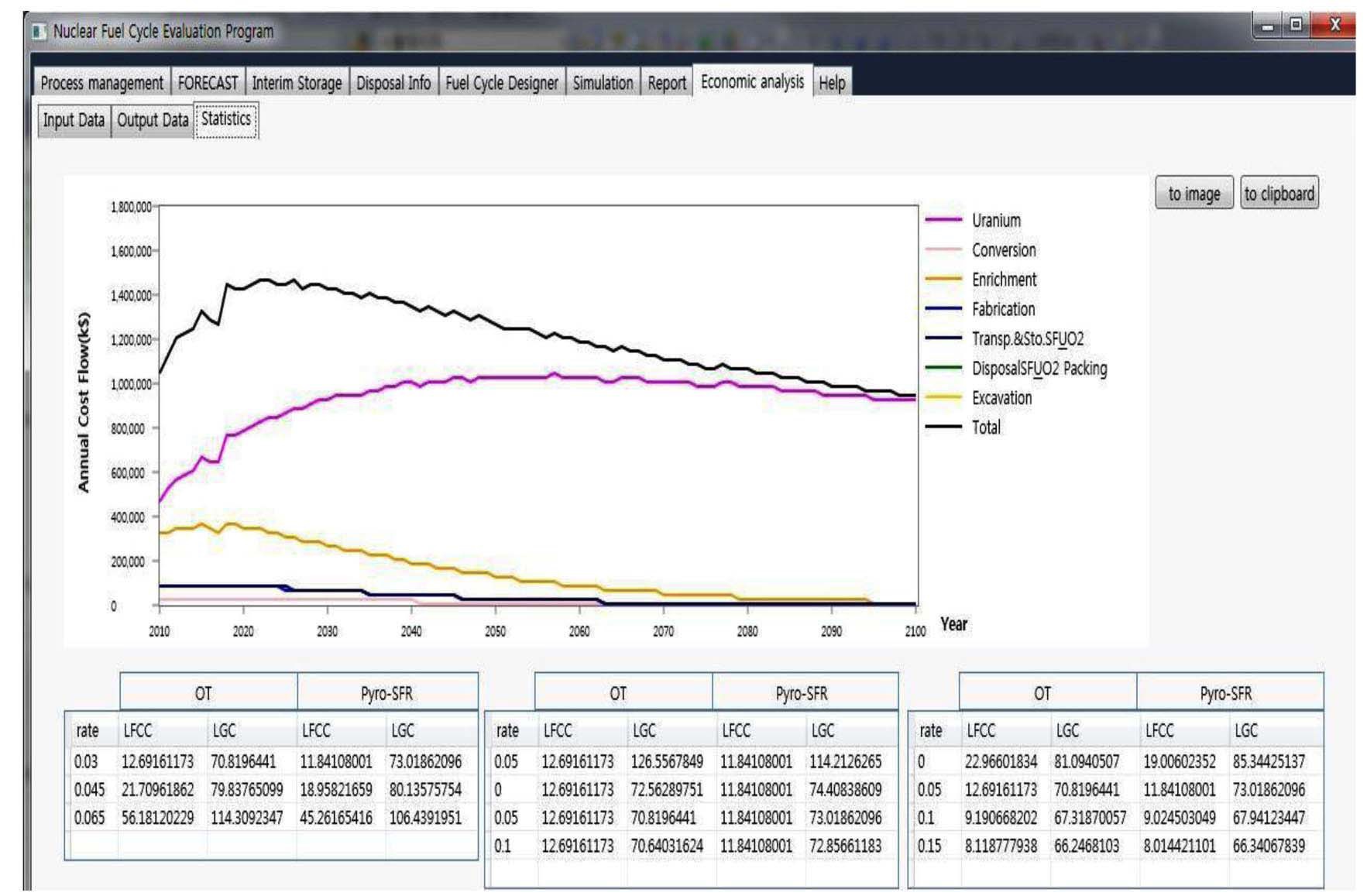
3.2.5 Nuclear Fuel Cycle Analysis Report
A report unit module provides information that can be used for a comparison of nuclear fuel cycle alternatives. For example, it represents the unit cost of each nuclear fuel cycle processing stage in the form of a curve graph, as shown in Figure 9, and the resulting data can be stored in an Excel file.
When developing the code, a software quality assurance procedure is very important, since only with the verified code calculation results can the code have credibility [15].
Generally, for software quality assurance, the procedures of verification and validation are required. These procedures are based on IEEE Std. 1012-2004 (IEEE Standard for Software Verification and Validation), which describes the stipulations on software development and maintenance [16]. However, in the field of nuclear energy, software quality assurance is specified in the design control of NQA 18 Criteria.
Software verification and validation are tests and evaluations that check whether the completed software satisfies the quality requirements. Accordingly, verification is conducted throughout the entire life cycle of the software. Here, the life cycle can be divided into the requirement stage, design stage, implementation stage, integration stage, verification and testing stage, installation and inspection stage, operation and maintenance stage, and extinction stage. Therefore, software verification is checking whether
the outcome of the stage satisfies the necessary requirements in the software life cycle.
Testing is checking whether a software program satisfies the quality requirements using various methods, or whether there is a gap between the expected and actual value. Testing is generally conducted using specific cases [17]. In test cases, the accuracy is validated by either comparing the expected output outcome using specific input data and the actual outcome or comparing the calculation outcome of other verified codes and the actual outcome.
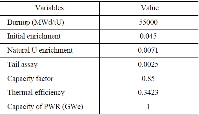
For verification of the FUTURE code, input data, as shown in Tables 4 and 5, was used. The code used for comparison is the FAST (nuclear Fuel cycle Analysis and Simulation Tool) code, which was developed by the
[Table 4.] Input Data for PWRs

Input Data for PWRs
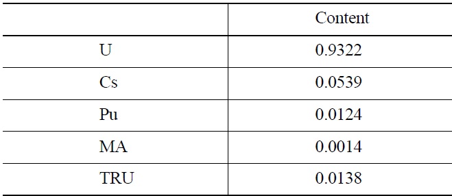
[Table 5.] Content of Major Nuclides in Spent PWR Fuel

Content of Major Nuclides in Spent PWR Fuel
Korea Atomic Energy Research Institute, based on Excel using the material flow calculation equation of the nuclear fuel cycle processing stage that was announced in the OECD/NEA 1994 Report. Verification was completed as early as 2005. It was implemented for the results of the material flow calculation of each processing stage of the nuclear fuel cycle in manual work. The main difference between the FAST code and FUTURE code is the design flexibility of the nuclear fuel cycle processing stage. In other words, with the FUTURE code, it is possible for a code user to design the entire nuclear fuel cycle process and simply conduct the simulation.
For software quality assurance, the uncertainty of the calculation results of the FUTURE code was measured using a statistical method in this paper. For this purpose and as a test case, the difference in the calculation value between the FAST code and FUTURE code for the direct disposal alternative was defined as shown in Equation (2). Using Equation (3), the standard error (uncertainty) for Zi was also calculated [18].
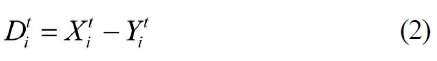
where
Xit = The calculated material quantity by FAST code
Yit = The calculated material quantity by FUTURE code
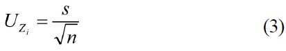
where
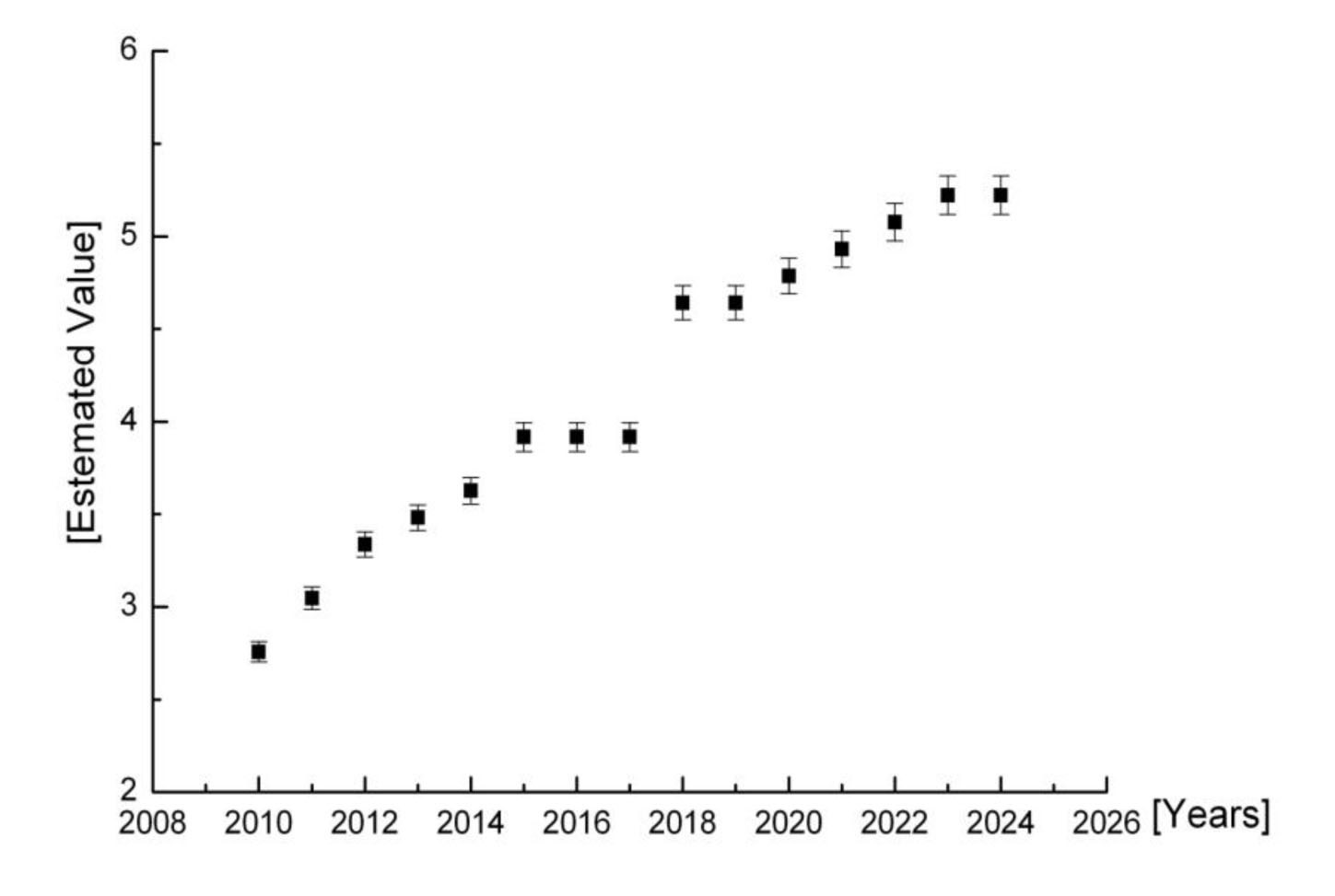
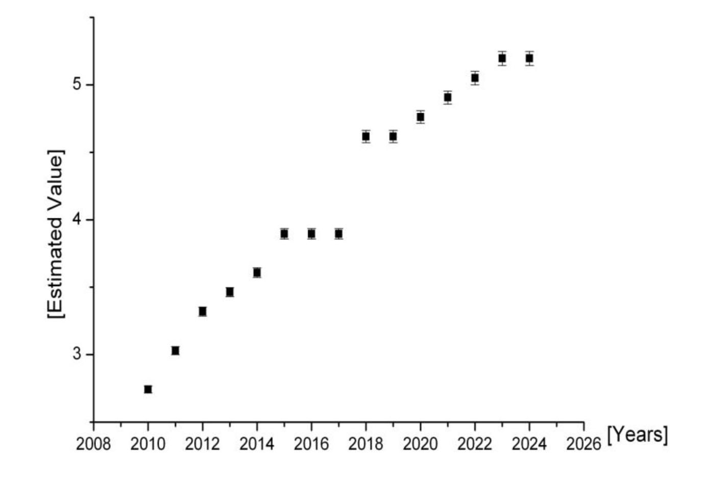
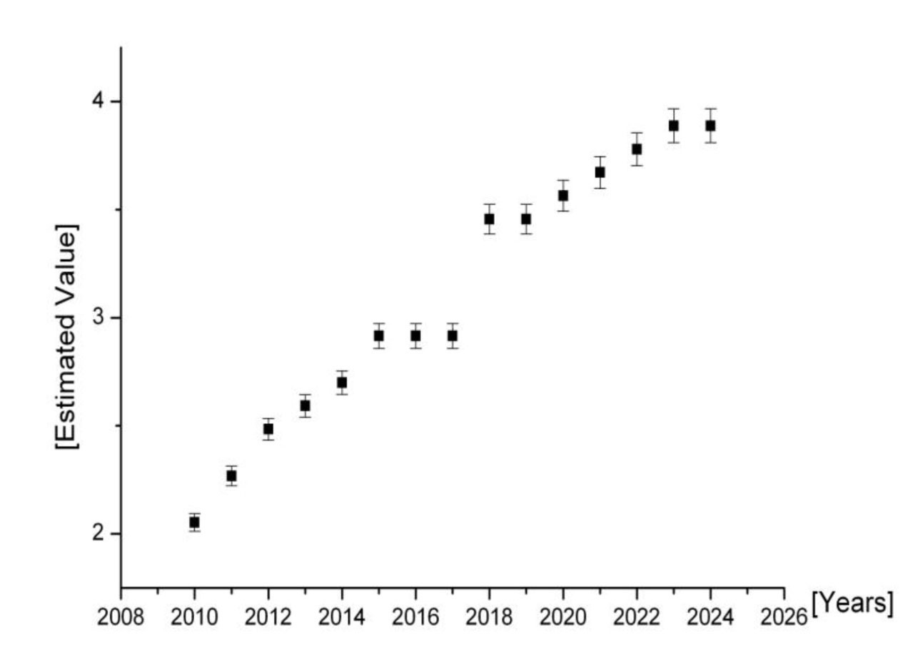
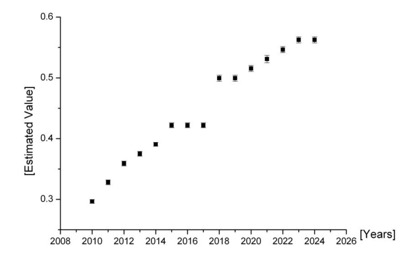
Figures 10 through 13 are graphic representations of standard errors for the difference in calculation results between the FAST code and FUTURE code in each processing stage, whereas Table 6 represents the difference in figures. The results show that the difference in the calculation results between the FAST code and FUTURE code is very small, and an assertion can be made that there is no problem in the calculation capacity of the FUTURE code as the calculation capacity of the FAST code was already verified [20].
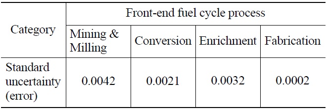
Standard Uncertainty for the Difference of Calculation Results between FAST and FUTURE Codes
In this paper, an attempt was made to present the implementation methods and detailed functions of each unit module program of the so-called FUTURE code, a nuclear fuel cycle analysis code. The validation methods for quality assurance of the nuclear fuel analysis code are also presented.
Each unit module program consists of standard information management, input data management, scenario information management, a simulation, and a report. The major functions of each module can be summarized as follows:
First, the standard information management module was implemented to manage the standard process, nuclear material and parameters, and nuclear information. Second, the scenario information management module constitutes master information and manages a nuclear fuel cycle analysis and basic information for an evaluation. Third, the process flow designer module selects the processes to be analyzed from the standard process list based on the scenario, and sets the inter-relationships of each process in the form of arrows. This kind of process design method was essentially formulated based on a Graphic User Interface (GUI), which provides a drag-and-drop method of the user interface, enabling an easy and fast nuclear fuel cycle process design. When the inter-relationship between the processes is set as well, user convenience is further enhanced as the front-end process and the back-end process are connected by the drag-and-drop method, enabling an automatic recognition of the nuclear fuel cycle processing sequence. Fourth, in the case of the electric demand forecast management module, when the target period of the analysis and the values of the variables are inputted, the electric demand forecast data by year is calculated and displayed on the screen. Fifth, the simulation model simulates the designed nuclear fuel cycle process and shows the resulting data by year. In particular, when the built-in basic scenario of the nuclear fuel cycle process is used, a simulation can be conducted more easily.
While a simulation can be run both in the forward and backward directions, a backward-direction calculation is possible only in the front-end nuclear cycle process. Sixth, the nuclear fuel cycle analysis report module aggregates the resulting data of the simulation, and has a reporting function through the use of charts.
In particular, when a validation is executed on the difference in the calculation results between the FAST code and FUTURE code using examples of a direct disposal alternative [19], the standard error for calculating the difference turned out to be very small.
The most conspicuous virtue of the FUTURE code lies in the fact that a nuclear fuel cycle processing stage can be designed very easily since it uses process components for each nuclear fuel cycle scenario. Unfortunately, however, it cannot generate data related to the decay of nuclides at each processing stage of the nuclear fuel cycle, requiring more research in the future.


![PWR-MOX (Mixed Oxide [UO2 and PuO2] Fuel) Cycle](http://oak.go.kr/repository/journal/12709/OJRHBJ_2013_v45n5_665_f004.jpg)


![Standard Error of Material Quantity in the Mining Process [unit: kTon]](http://oak.go.kr/repository/journal/12709/OJRHBJ_2013_v45n5_665_f010.jpg)
![Standard Error of Material Quantity in the Conversion Process [unit: kTon]](http://oak.go.kr/repository/journal/12709/OJRHBJ_2013_v45n5_665_f011.jpg)
![Standard Error of Material Quantity in the Enrichment Process [unit: SWU]](http://oak.go.kr/repository/journal/12709/OJRHBJ_2013_v45n5_665_f012.jpg)
![Standard Error of Material Quantity in the Fabrication Process [kTon]](http://oak.go.kr/repository/journal/12709/OJRHBJ_2013_v45n5_665_f013.jpg)