Passive safety systems are being considered in new and advanced designs for enhanced safety and reliability, and to reduce human intervention. Conventionally, passive systems are incorporated to simplify the design by reliance on natural physical laws, for transparent safety, to provide an ample grace period for the operator, for ease of operation and maintenance, etc. Moreover, for densely populated countries, large-scale deployment of reactors in future requires the designers to elevate the design goals, such as having no impact in the public domain. This further reinforces the need for passive safety systems in advanced reactors. The Advanced Heavy Water Reactor (AHWR) is one such reactor with due emphasis on passive safety. It is a pressure-tube type heavy water moderated and boiling light water cooled reactor designed with the twin objectives of thorium utilization and a demonstration of enhanced safety derived from various passive features [1].
AHWR incorporates natural circulation for core heat removal under all plausible conditions of a reactor, namely startup, power rise, shutdown and accidental conditions, including loss of coolant accident (LOCA) and station black out (SBO). The design goals of AHWR include the elimination of severe plant conditions, and hence emergency preparedness by reliance on passive safety features resulting in significantly improved figures of merit in terms of core damage frequency (CDF) and large early release frequency (LERF). This is achieved by incorporating the capability to shutdown the reactor safely, remove decay heat safely and maintain the integrity of the ultimate barrier that is containment, even under the worst credible scenarios.
AHWR design draws significantly from the past experiences of operating reactors, the major accidents that have brought renewed perspective to safety, and the foresight of emerging threats to safety, particularly malevolent acts or sabotage. This paper examines the capability of the reactor to withstand the accidents postulated along the lines of major accidents in the history of nuclear power reactors, namely the Three Mile Island, Chernobyl and Fukushima accidents. For the purpose of analysis, RELAP5/Mod3.2 was chosen as a best estimate system thermal-hydraulic code. It may be noted that this code has been extensively used for simulations of transient and safety analysis of water-cooled reactors in the past [2,3]. Besides, the code has been extensively validated with test data from several separate effect as well as integral test facilities for water-cooled reactors [4,5].
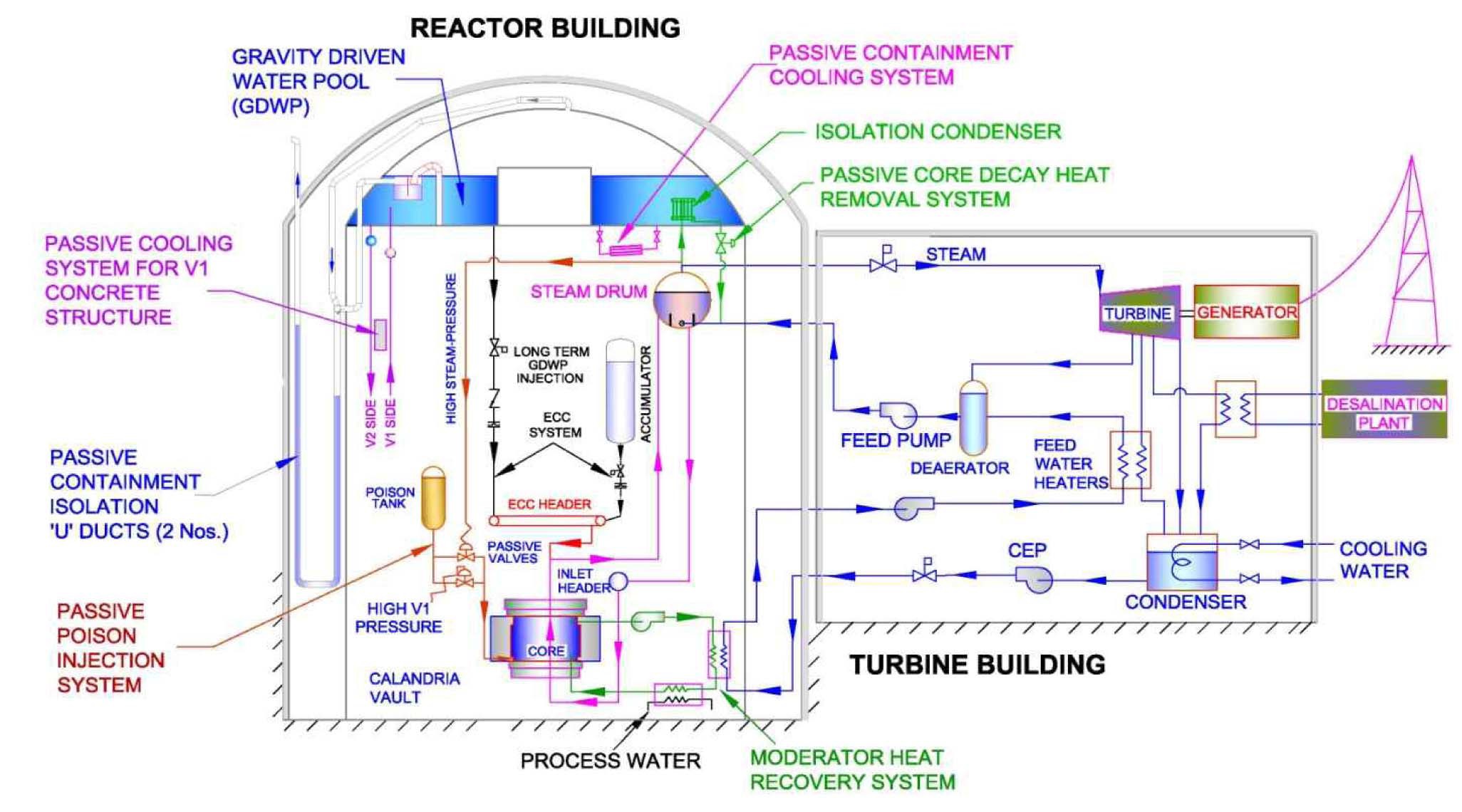
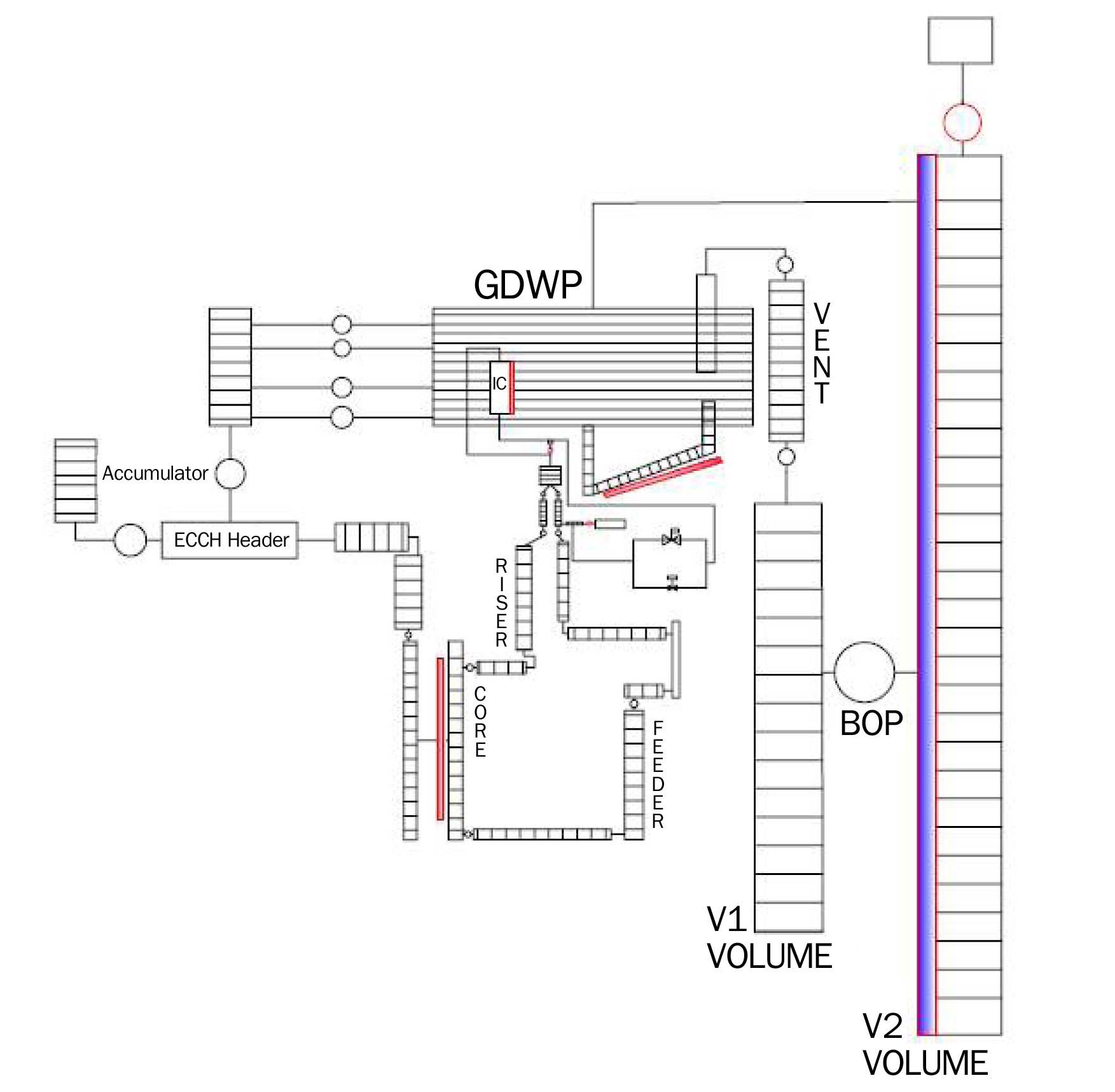
AHWR is a vertical pressure-tube type boiling water reactor with heavy water as moderator and light water as coolant (Fig. 1). The reactor is designed with the twinobjectives of early development of the technologies relevant to the third stage of the Indian Nuclear Power Programme that aims at thorium utilization and the demonstration of innovative passive safety features consistent with the safety requirements of next generation reactors. Natural circulation for core cooling under all conditions is the most prominent passive feature. It eliminates all the scenarios of safety significance that may result from the unavailability of pumps. Table 1 shows the main design parameters of AHWR.
A schematic of a natural circulation based heat transport
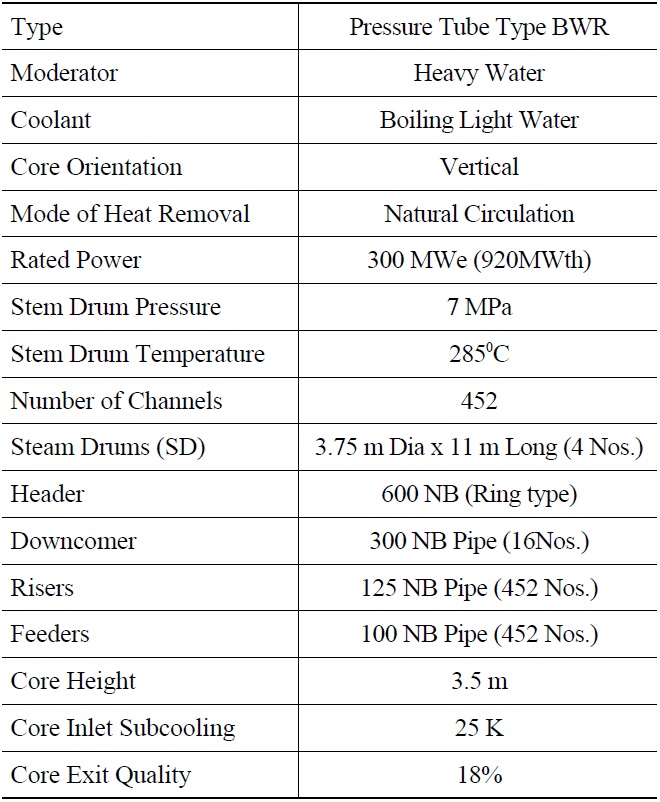
[Table 1.] Main Design Parameters of AHWR

Main Design Parameters of AHWR
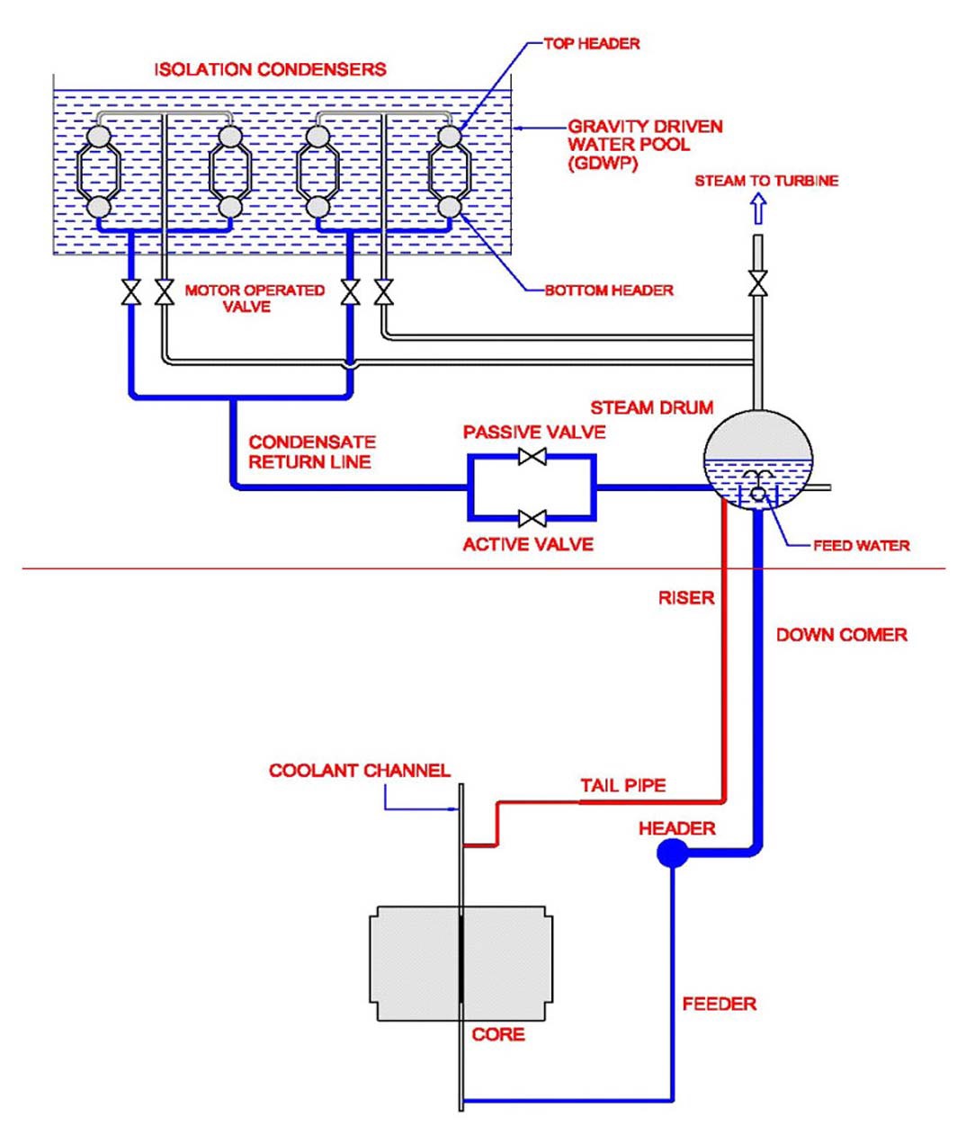
system of AHWR is shown in Fig. 2. The main heat transport system (MHTS) is comprised of four identical parallel loops connected to each other through a common header and a common steam line supplying the steam to a turbine.
The header is connected to the core of the reactor through feeders. The subcooled water that enters the reactor core gets heated and leaves the core as two-phase flow. The steam-water mixture leaving the core flows upward through the risers, which are connected to the four horizontal steam drums. The gravity based steam-water separation takes place in the steam drums. The saturated steam leaving the steam drums flows to the turbine through the steam lines. The separated water in the steam drum mixes with the subcooled feedwater entering through the feedwater sparger in the inter-baffle region. This subcooled water returns through the downcomer pipes to the common header and thus completes the four natural circulation loops, each catering to a quarter symmetric section of the core and having a steam drum. The baffles separate the sections of the steam drum connected to the risers and downcomer, thus enabling the separation of steam and water. Each feedwater line is provided with a flow control valve, which is governed by a three-element based controller. The system pressure is maintained by a valve located downstream in the steam line i.e. turbine governor valve. Under normal operating condition, the core power is 920 MWth. The subcooled water enters the core at 260℃ (25K subcooling) and leaves as a steam-water mixture of 18% quality. Saturated steam is produced at 70 bar that drives the turbine, and the same mass flow rate of feedwater enters the steam drum at 130℃. In addition, the AHWR design employs many inherent and passive features [1] as mentioned below:
Slightly negative void reactivity coefficient
Passive isolation condenser system for decay heat removal
Passive emergency core cooling
Passive poison injection system to ensure shutdown following failure of wired shut down systems
Passive containment cooling
Passive containment isolation
Passive auto-depressurization system
2.1 Important Safety Systems in AHWR
2.1.1 Passive Decay Heat Removal System
Isolation condenser system (ICS) (Fig. 2) is comprised of a set of immersed condensers in an elevated water pool i.e. Gravity Driven Water Pool (GDWP), and associated piping and valves [2]. ICS is essentially designed to remove the decay heat in the event of an SBO or the unavailability of the main condenser. Normally, the main condenser serves as a decay heat removal system, however, in case of the unavailability of the main condenser or SBO, the ICS gets valved in. A branch connection from the steam line carries the steam to a tube bundle of immersed condensers through a distributor and top header. The steam condensation takes place in the tube bundle and the condensate returns to the downcomer region of the steam drum through a bottom header and condensate return line. The condensate return line is provided with a set of active and passive valves in parallel. The heat removal capacity is regulated using a passive valve where the valve opening is regulated depending on steam drum pressure, thus maintaining hot shutdown. The passive valve actuates directly on the variation of steam drum pressure in a specified range. The active valve (pneumatically operated) provided in parallel serves the purpose of bringing the system to a cold shutdown condition, if required. Under normal operation, the valves remain closed, thus isolating the ICS from the MHTS, and steam flows to the turbine circuit, whereas, under shutdown conditions, the turbine is isolated from the MHTS, the passive valve opens (and closes also) in response to steam drum pressure, and a natural circulation path is established between the MHTS and ICS.
2.1.2 Passive Emergency Core Cooling System
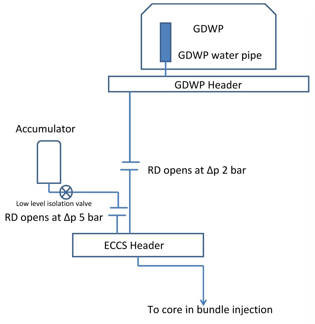
This is comprised of an injection of water directly into the reactor core in three stages. In the first stage, injection from an accumulator takes place on the MHTS low-pressure signal (50 bar). In the second stage (MHTS pressure 2 bar), the water flows under gravity from the GDWP, providing core cooling for three days. In the third stage, water accumulated in the reactor cavity is pumped back to the GDWP, which eventually enters the core. The first and second stages of emergency core cooling system (ECCS) are passively actuated and do not depend on any active component. Figure 3 shows the schematic arrangement of ECCS of AHWR.
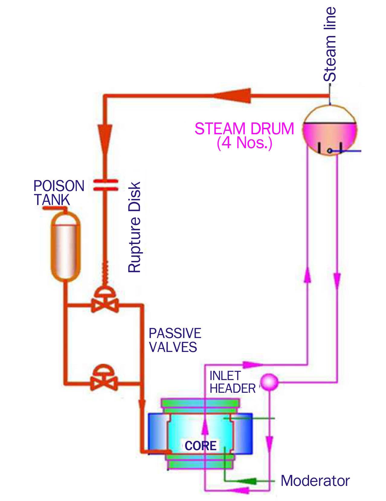
2.1.3 Passive Poison Injection System
This passive system injects the poison into the moderator by using the increased steam drum pressure, in case of a very low probability event of failure of both the wired shutdown systems, accompanied with a transient involving the unavailability of the heat sink. Figure 4 shows the schematic of the passive poison injection system. AHWR design has two independent shutdown systems, one comprising the mechanical shut off rods and the other employing injection of a liquid poison into the low-pressure moderator. Both the shutdown systems require active signals for shutdown of the reactor.
3. POSTULATED ACCIDENT SCENARIOS WITH POTENTIAL TO CAUSE SEVERE PLANT CONDITIONS
In view of the importance of the few major accidents in the history of the operating reactors, it is imperative to demonstrate the safety of a new design against accidents postulated along similar lines. The following sections aims to bring out the highlights of the three major accidents, without getting into the minute details, and draw a parallel scenario for AHWR to the extent conceivable in such a design. The accidents are described briefly with the aim of postulating an appropriate sequence of similar events for AHWR.
The Chernobyl accident was essentially a combination of certain undesirable design features and a violation of
safety culture [6]. The RBMK design had a positive reactivity coefficient, a faulty design of control rods, and lack of containment structure. However, in spite of these design deficiencies, RBMK reactors have successfully performed; the precursor to the Chernobyl accident was in fact the specific experiment that was conducted in gross violation of safety culture, for example the bypassing of many safety systems. The Chernobyl accident was the second major accident after TMI, but it was the first accident in terms of radioactivity release and serious impact on the public perception towards nuclear electricity generation. The reactor design had certain undesirable characteristics in addition to those mentioned above, like use of graphite as a moderator at such high temperatures, which is prone to fire, and lack of containment envelop, which magnified the consequences of the accident.
Though the AHWR design incorporates a slightly negative reactivity coefficient achieved by reactor physics design based on tight lattice, and eliminates the possibility of undesirable reactivity addition by limiting the maximum worth of control rods, as well as the maximum speed of drives, an attempt has been made to postulate a similar scenario that may lead to inadvertent reactivity addition in AHWR. This postulated scenario is particularly relevant in case of malevolent acts where both the wired shutdown systems are disabled and the main condenser is not available. Besides, even a small negative void reactivity coefficient may also lead to undesirable power excursion in case of an inadvertent reactivity addition, thus justifying the need for assessing the reactor with passive systems to cope with it safely.
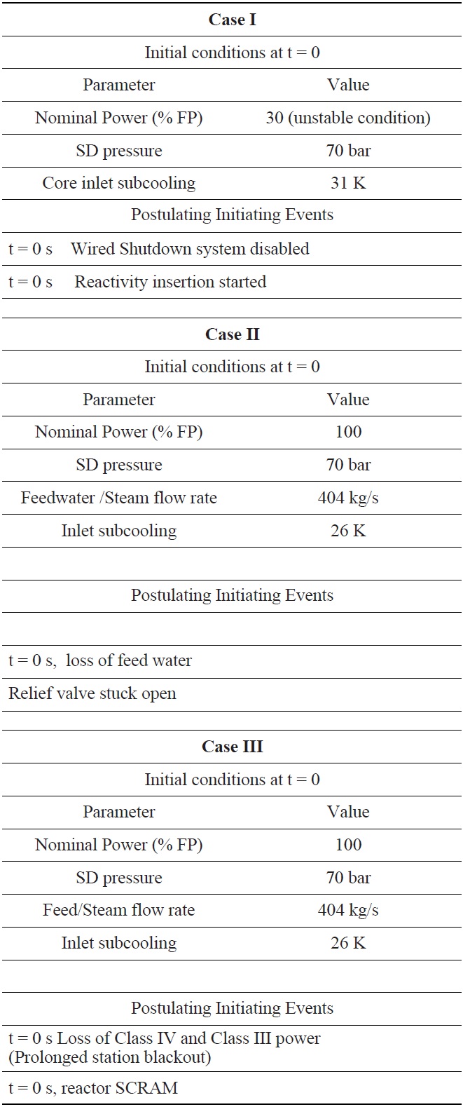
For the case of AHWR undergoing a similar initiating event, it is postulated that the reactor is initially operating at 30% full power with a high core inlet subcooling (31K), such that it has entered into an unstable operation domain. With the occurrence of instability, the reactor should have tripped, based on signals from channel flow monitors and local power range monitors (LPRM) employed in the core. However, it is postulated that the operator has disabled both the wired shutdown systems and regulating rods are withdrawn to increase the power to enter into the stable natural circulation domain. The reactivity addition takes place at the maximum possible rate as permitted by the design.
The TMI accident [7] was in fact an outcome of overdependence on human intervention that led to erroneous operator response, partly driven by faulty instrumentation and a faulty diagnosis of the event. The accident highlighted the severity of small break LOCA. The TMI accident brought a paradigm shift in nuclear reactor technology, highlighting the importance of passive safety over the conventional practice of active safety and operator intervention. At TMI, it was essentially a small break LOCA, due to a stuck open power operated relief valve, such that the reactor could not depressurize enough to activate the emergency core cooling until late in the accident. Further, with the faulty diagnosis of water level rise in the pressuriser, the high-pressure injection was tripped by operator intervention. The condition resulting from the stuck open relief valve could have been managed with activation of engineered safety systems provided in the design. However, operator action essentially denied the actuation of ECCS and in turn, a normal upset catapulted into an accident. However, safety philosophy based on multiple barriers precluded any significant release of radioactivity to the operator and public.
In AHWR, the main heat transport system is provided with relief valves to prevent the over-pressurization in event of partial or complete unavailability of the heat sink. For the purpose of the simulation of a similar plausible accident in AHWR, it is considered that the reactor is operating at full power and experiences a sudden loss of feedwater with a turbine trip. As a result, the reactor gets bottled up due to the closure of the main steam isolation valve (MSIV). At the same time, the isolation condenser system is considered to be unavailable, which is very unlikely as the system is passive in operation. However, it is postulated to deprive the reactor of a heat sink as it happened at TMI due to the unavailability of feedwater on the secondary side of steam generators. This in turn leads to a situation where steam drum pressure builds up to the set point of the safety relief valve (SRV). However, the safety relief valve fails to reseat and remains stuck open, causing a loss of coolant accident. It may be noted that ECCS availability can be reasonably justified, as its actuation is made passive by the incorporation of a rupture disk.
The Fukushima accident [8] was essentially an external event induced accident that led to prolonged station blackout (SBO). The beyond-design-basis earthquake induced Tsunami caused not only the failure of the transmission grid, but also drowned the diesel generator sets provided to supply class III power in the event of a failure of class IV power. In addition, the natural calamity rendered the plant site inaccessible for several days to preclude external intervention to rescue the situation and thus further aggravated the accident. Though SBOs have always been considered in the reactor design and safety philosophy, the Fukushima accident raised a question on the mission time that the design must consider in view of such a prolonged SBO. It may be noted that the plant withstood a beyond-designbasis earthquake without any impact on the structural integrity and the reactor could be safely shutdown, thus demonstrating the reliability of the structural design and shutdown system. In the context of AHWR, though the Indian coasts are not prone to such Tsunamis because of geographical factors, and layout provisions ensure the safety of diesel generator sets, a prolonged SBO can be postulated to demonstrate the robustness of the in-built design features. It is postulated that there is a simultaneous failure of class IV and III power supplies leading to the closure of the Combined Isolation and Emergency Stop Valve (CIESV) as well as loss of feedwater supply to the steam drums. This condition is assumed to remain for several days. It may be noted that the inlet to ICS is always in communication with MHTS, whereas, a set of passive, as well as active, valves are provided in parallel in the condensate return line at the outlet of IC. The motor operated valves provided are always open and closed only for the purpose of isolation during the maintenance work. The passive valve operation is governed by the steam drum pressure, whereas the active valves are pneumatically operated based on a fail-safe design such that it opens when the pneumatic supply is exhausted.
4. SYSTEM ANALYSIS FOR POSTULATED ACCIDENTS
The reactor system has been analyzed using the best estimate code RELAP5/Mod3.2 [9]. The code has been successfully applied for simulation of passive systems of AHWR by comparing the code predictions and test data obtained from an integral test facility. For the purpose of this analysis, following assumptions are made:
All channels are lumped into a single channel
Point Kinetics model for reactor kinetics simulation is considered
A nodalisation of the entire system comprising MHTS, ECCS, ICS and Containment System has been developed as shown in Fig. 5. Table 2 shows the initial conditions and postulated initiating events for all the cases.
[Table 2.] Initial and Boundary Conditions for All the Cases

Initial and Boundary Conditions for All the Cases
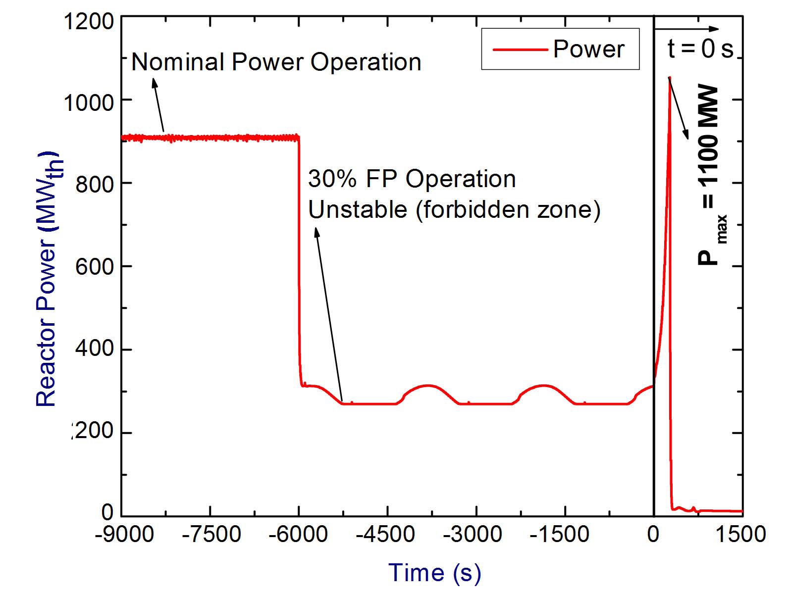
4.1 Analysis for Case I - Chernobyl Type Accident
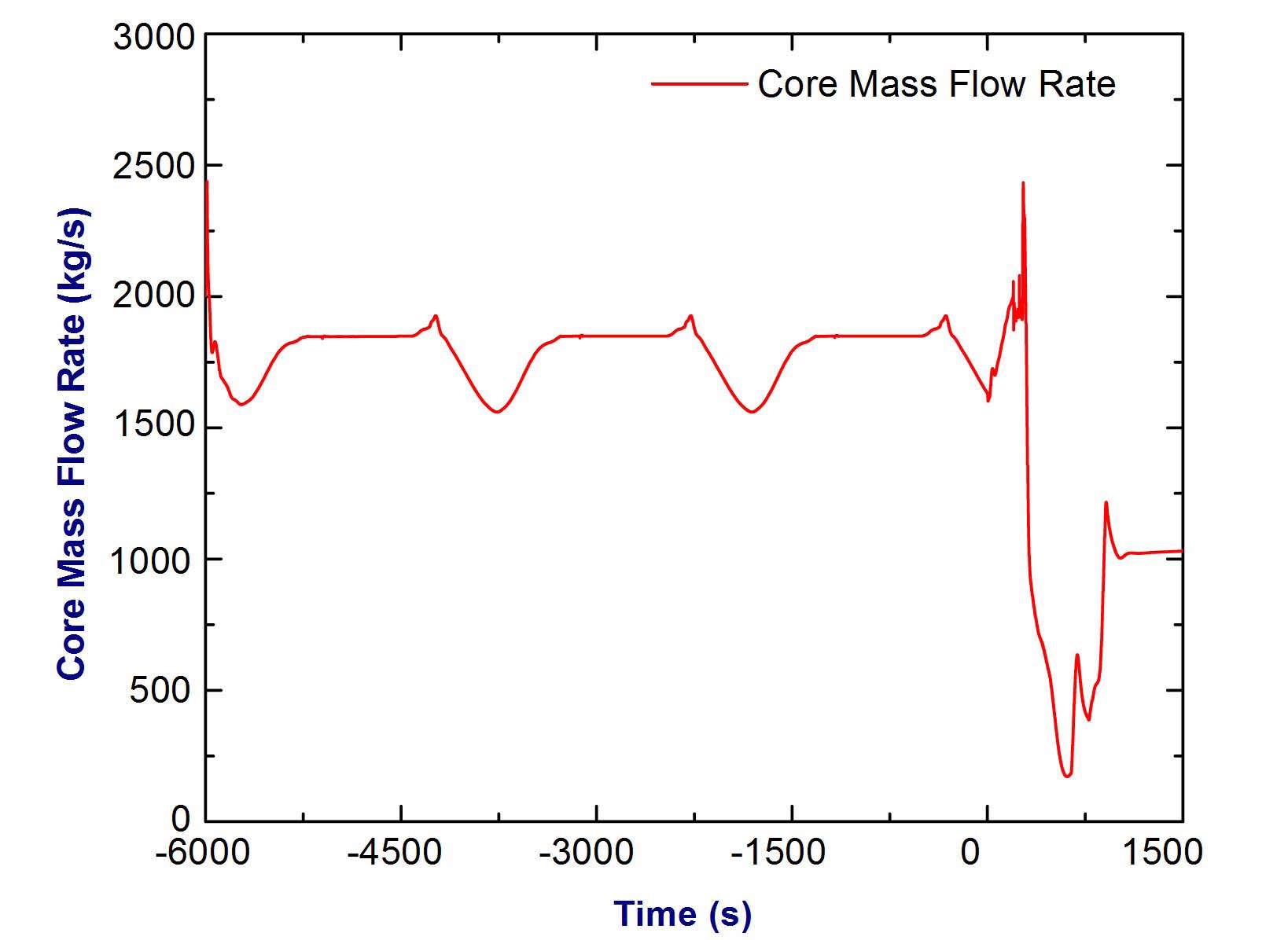
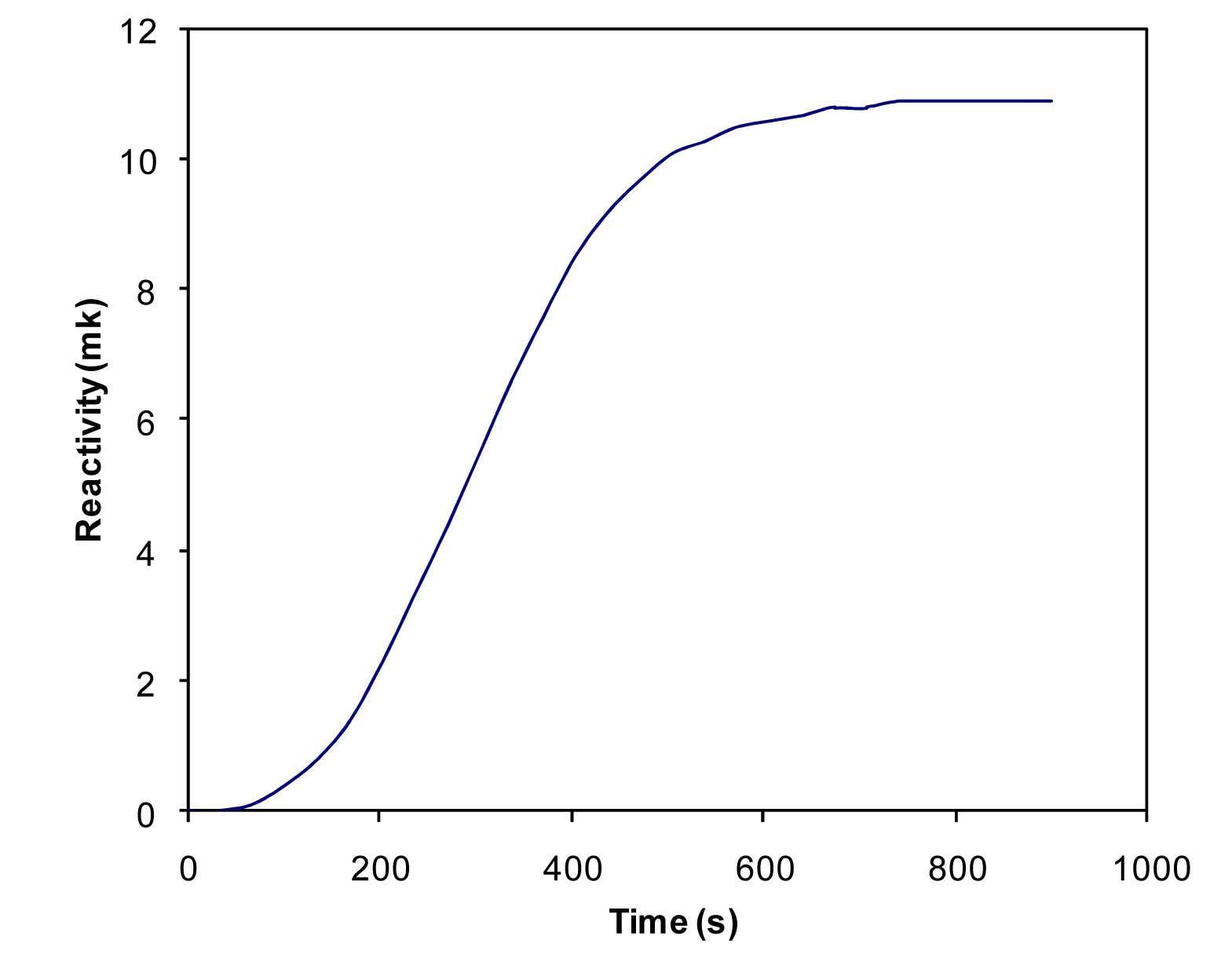
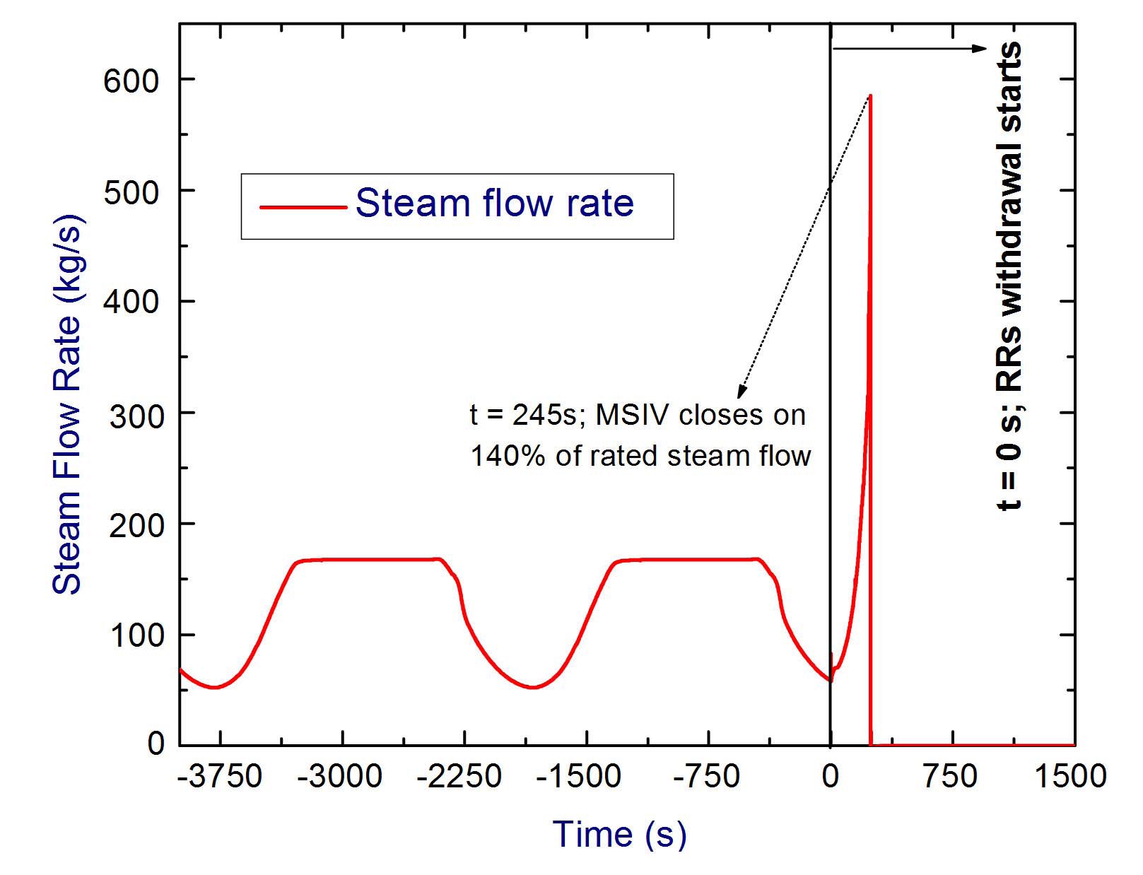
Initially the reactor is operating at 30% full power with high core inlet subcooling (t < 0 s). This leads to core flow oscillation as shown in Fig. 6. At t = 0 s, the operator disables the wired shutdown systems and removes all regulating rods to raise the power, so as to avoid unstable operation. This leads to a reactivity addition of 11 mk in 900 s as shown in Fig. 7. Due to this, core power increases rapidly with a corresponding increase in the steam generation rate, as shown in Fig. 8 and Fig. 9 respectively. It can be seen that the core power reaches 1100 MW at t = 272 s. However, at t = 245 s, the steam flow exceeds the 140% of the rated steam flow, causing the closure of main steam
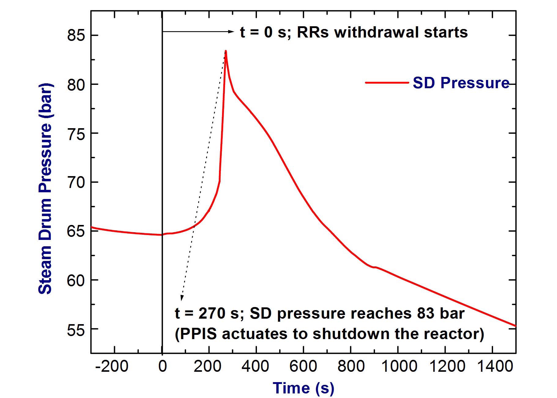
isolation valve, as shown in Fig. 9. Due to the bottled up condition of the reactor, the steam drum pressure rises
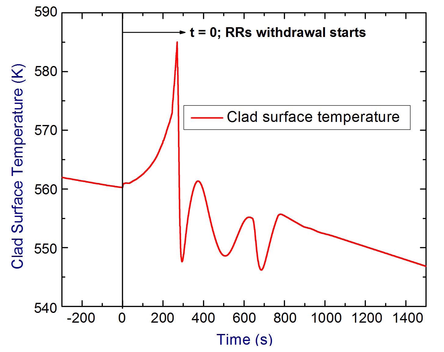
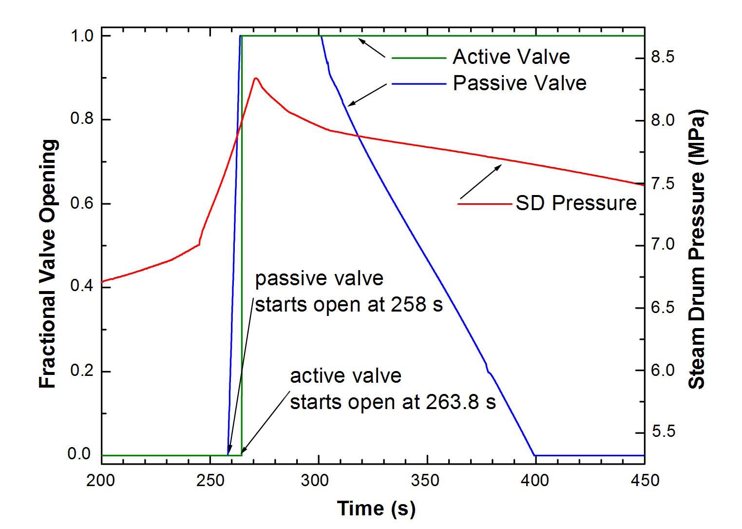
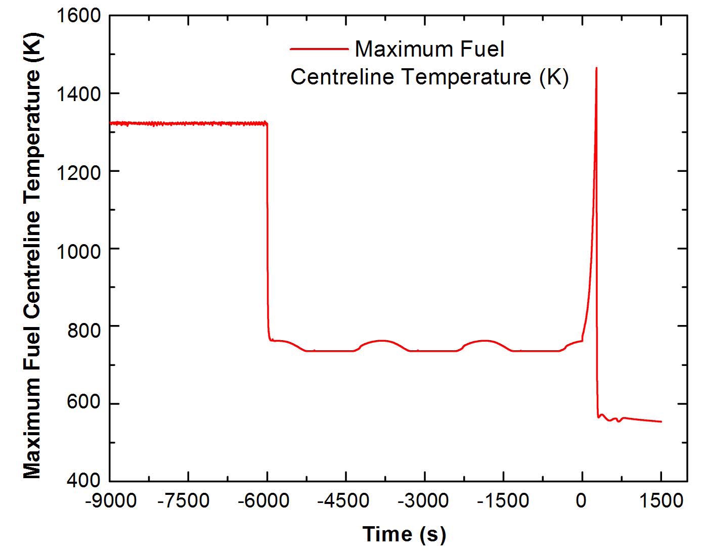
rapidly. The evolution of steam drum pressure during the accident is shown in Fig. 10. As the wired shutdown systems are not available, the corresponding reactor trips of high pressure are ignored. However, the isolation condenser system gets valved in as the passive valve starts opening at 76.5 bar. Since the isolation condenser is designed to remove the decay heat, the pressure continues to rise until the passive valve opens fully at 79.5 bar. Later, when pressure exceeds 80 bar, the active valve also opens at t = 263.8 s, as shown in Fig. 11. Further, due to the mismatch of heat generation in the core and heat rejection through ICs, as shown in Fig. 12, the steam pressure rises to 83 bar at t= 270 s. At this time, the passive poison injection system actuates on the bursting of the rupture disk, and ensures the reactor scram in a period of 2 seconds by injection of poison into the moderator. Subsequently, the reactor cooling is ensured by the isolation condenser system. The effect of a power excursion on the fuel elements can be observed from the Figs. 13 and 14, showing maximum clad surface
temperature and maximum fuel centerline temperature during the course of the transient, respectively. It shows that peak clad temperature reaches only to 585 K, whereas the maximum centerline temperature is found to be 1465 K, ensuring no loss of integrity in the fuel.
The above analysis not only indicates the capability of the reactor to withstand such a reactivity excursion as a result of a deliberate action or otherwise, but also signifies the role of the negative void reactivity coefficient, limitations on the reactivity insertion rate by way of limited worth, and the speed of the drives. Most importantly, it demonstrates the role of passive poison injection system in ensuring the reactor scram, on the basis of steam drum pressure in the event of a failure of two physically and functionally independent wired shutdown systems.
4.2 Analysis for Case II - TMI Type Accident
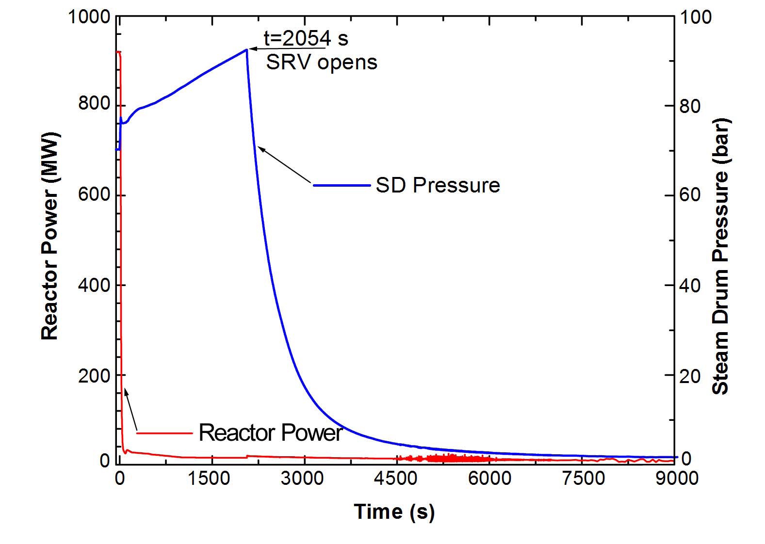
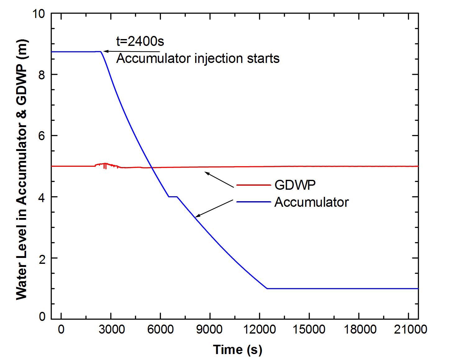
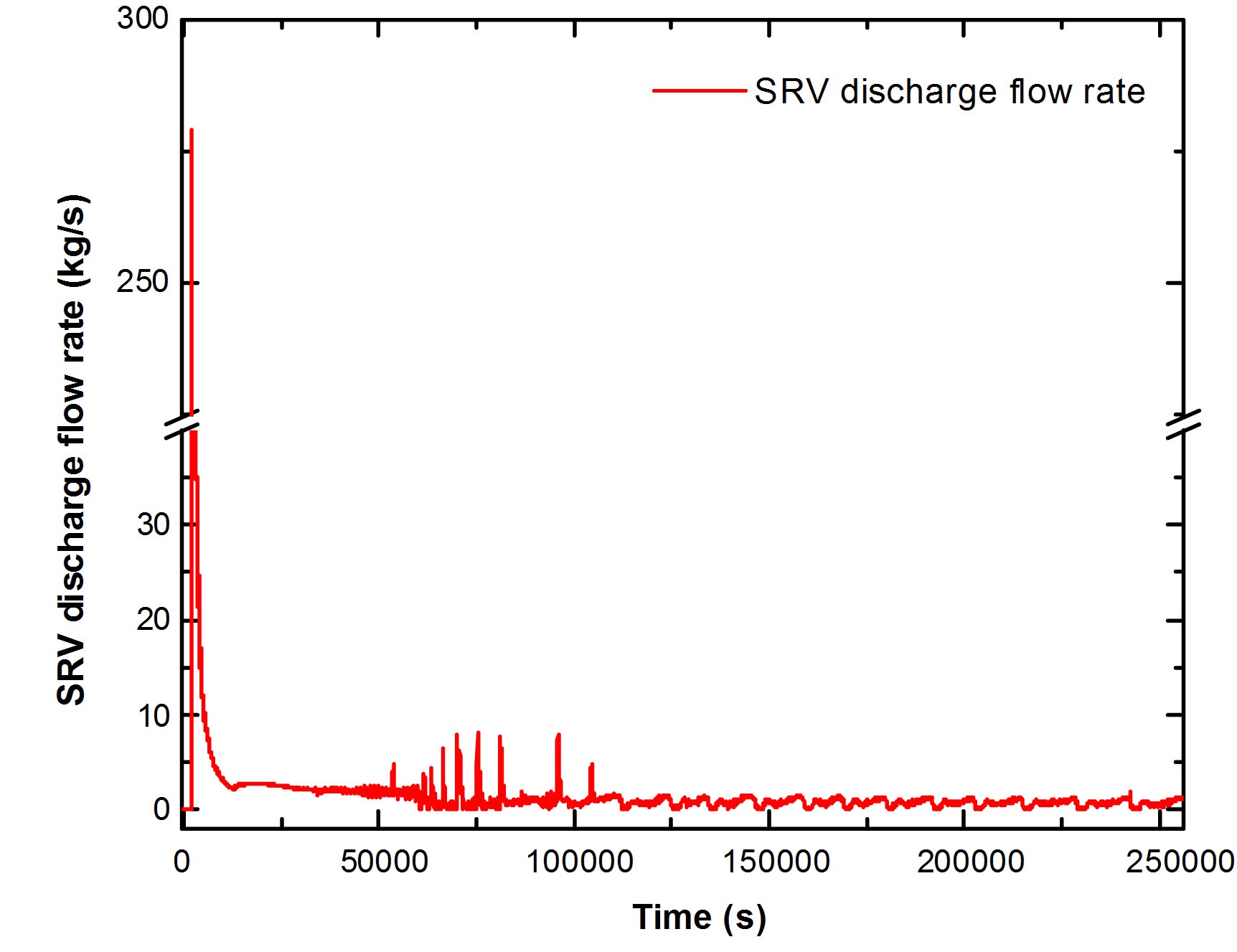
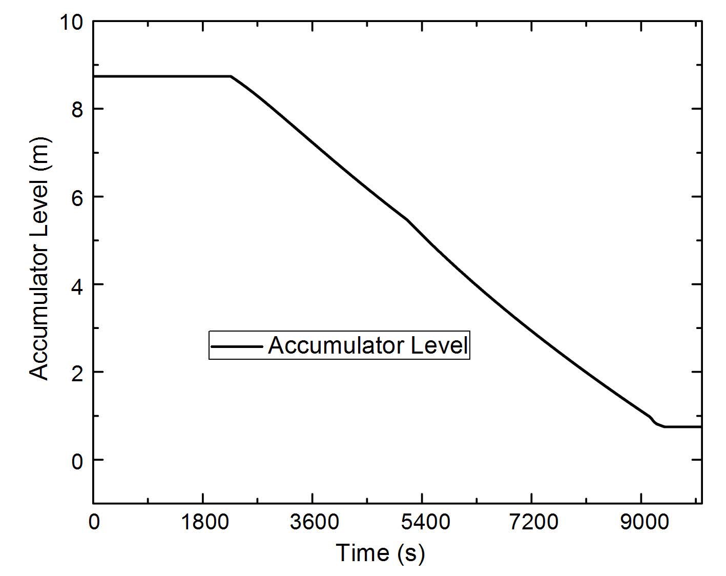
With the reactor operating at nominal operating conditions, at t = 0 s, sudden loss of feedwater is postulated. As a result, the turbine is tripped and the main steam isolation valve closes, resulting in a bottled up condition of the reactor. As the pressure rises, the reactor trips on the high-pressure signal at a steam drum pressure of 76 bar. At the same time, the unavailability of isolation condensers is also postulated. Thus, a complete loss of the heat sink occurs, that leads to pressurization of MHTS under decay heat. Figure 15 shows the steam drum pressure during the course of the transient. It can be seen that the pressure continues to rise to the set point of the safety relief valve mounted in the steam line. The safety relief valve is considered to remain stuck open, resulting in a loss of coolant accident. The safety relief valve discharges into the GDWP, the steam from MHTS condenses, causing depressurization of MHTS. At MHTS pressure of 50 bars, the accumulators get valved in and the first phase of ECCS injection initiates. Figure 16 shows the accumulator water level during the phase. However, accumulators gets isolated at t =12500 s
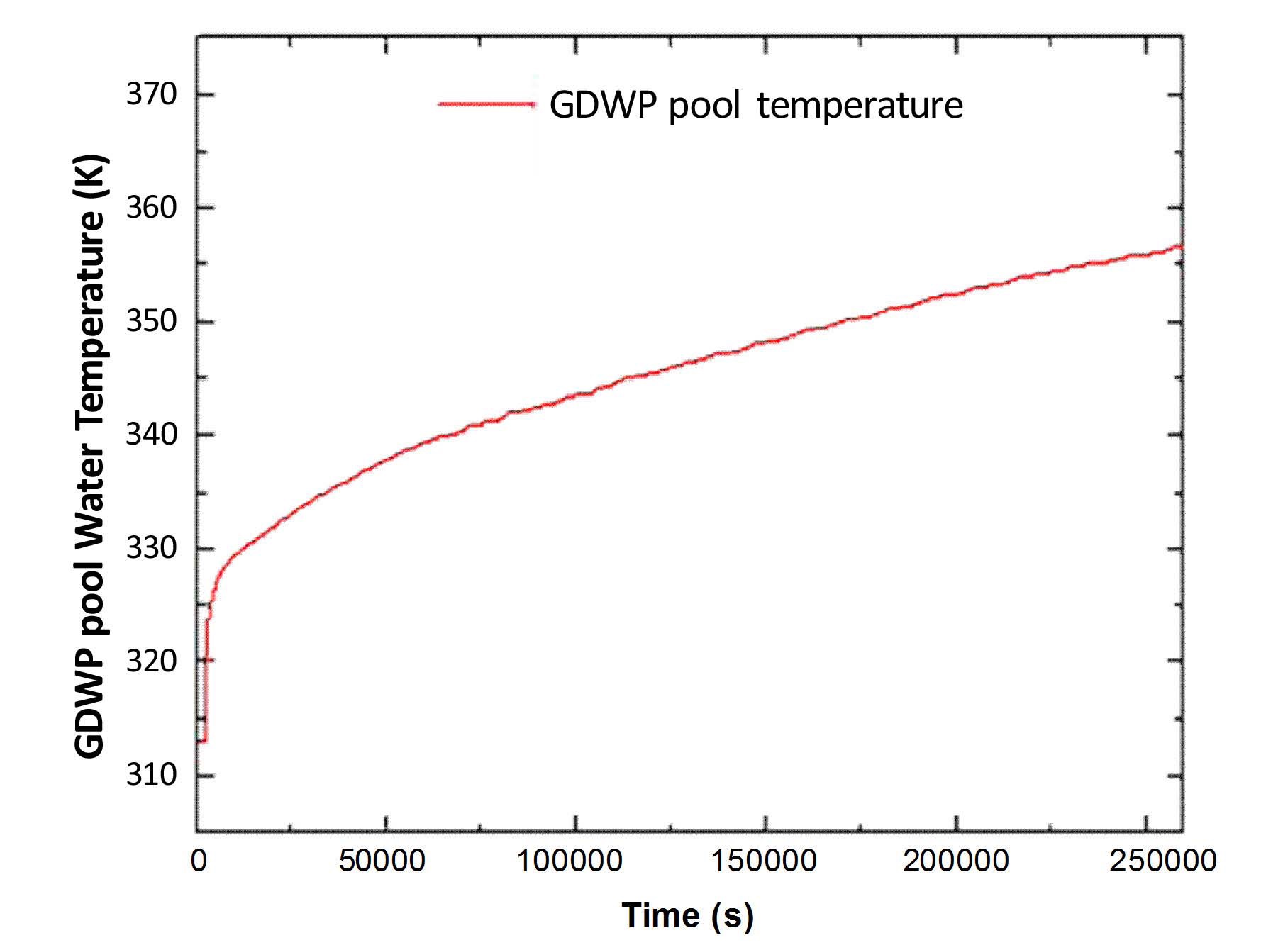
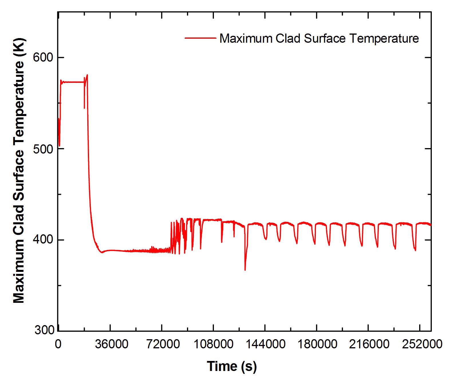
on account of the low accumulator level and the system pressure reduces. Subsequently, the second phase of the ECCS injection initiates, which is comprised of water injection from GDWP at the time when MHTS pressure reaches 2 bars. With valving in of GDWP, MHTS and GDWP are in communication forming a loop such that the steam condenses in GDWP and the same amount of water enters the core as emergency core coolant. Figure 17 shows the steam flow leaving the SRV. The GDWP water temperature rises for the period of 3 days, as shown in Fig. 18. The maximum clad surface temperature during the course of transient is shown in Fig. 19. It can be seen that maximum clad surface temperature is 575K, which is well within the safety limits.
4.3 Analysis for Case III - Fukushima Type Accident
Initially (t < 0) the reactor is operating at rated conditions and at t = 0 s, there is an earthquake which induces an SBO. The reactor trips safely on the earthquake signal. As a
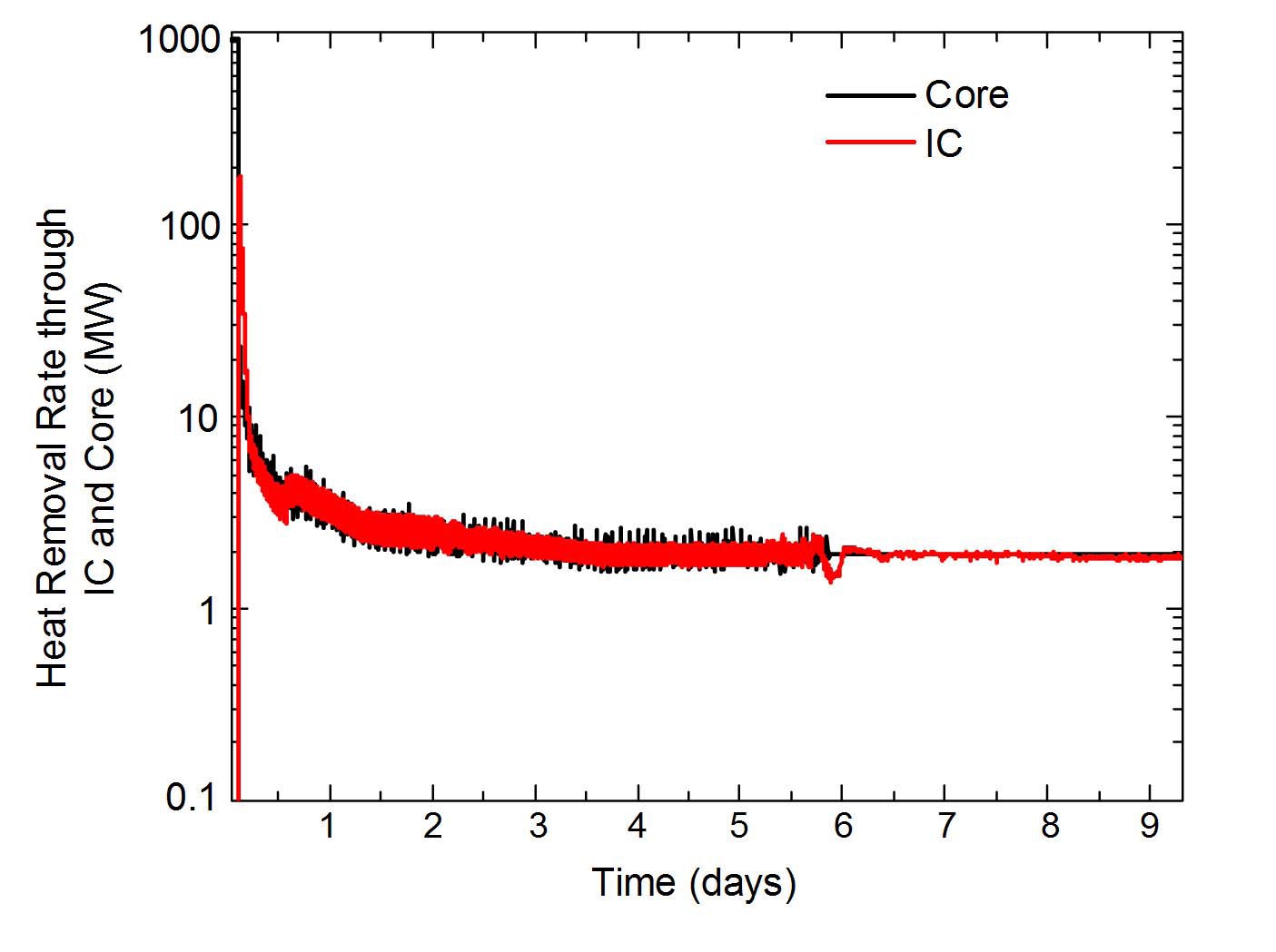
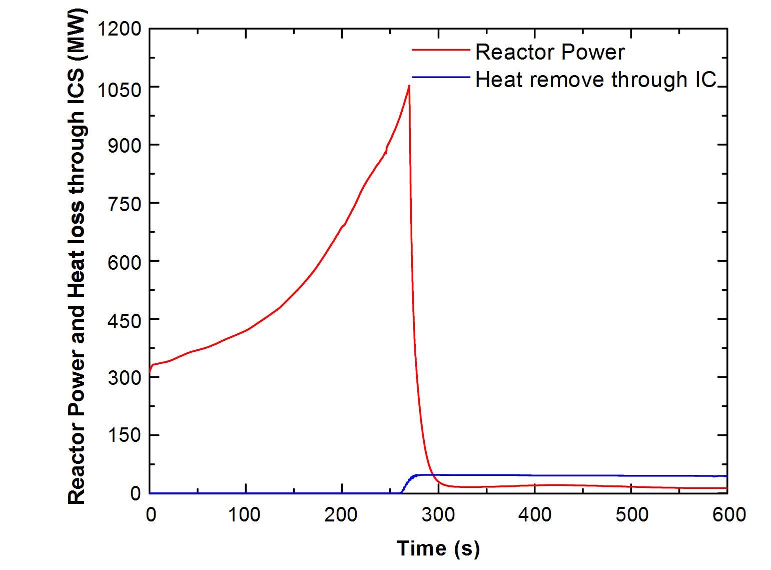
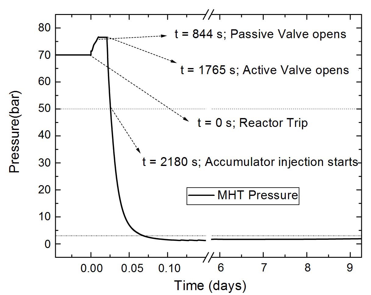
result of this initiating event, the feedwater supply to the steam drum is not available, and the combined isolation and emergency stop valve gets closed, thus leading the reactor to a bottled-up condition. The evolution of the steam drum pressure during the accident is shown in Fig. 20. It can be seen that, initially the steam drum pressure rises until the isolation condenser system gets passively valved-in at 76.5 bar. The hot shutdown passive valve maintains the pressure, however, the active valves in parallel to the passive valves also open with a delay of half an hour on the unavailability of compressed air due to the fail-safe design feature. Subsequently, the reactor depressurizes and decay heat removal continues through the isolation condensers using the GDWP water. Figure 21 shows the comparison of heat removed through the IC and heat transferred to coolant in the core. As the heat removal rate thorough IC exceeds the heat transferred to the coolant in the core, the main heat transport system continues to depressurize. It leads to pressure falling below 50 bar at t=2180 s
thus initiating accumulator injection. Accumulators become exhausted at t= 9380 s as shown in Fig. 22. It may be noted that, ECCS injection is available in a passive manner as actuation is based on the bursting of the rupture disks.
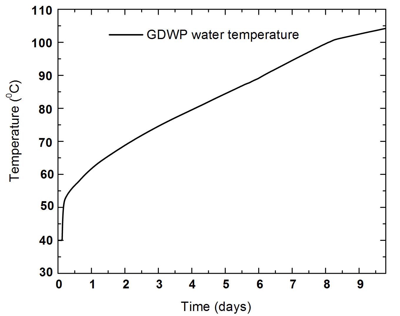
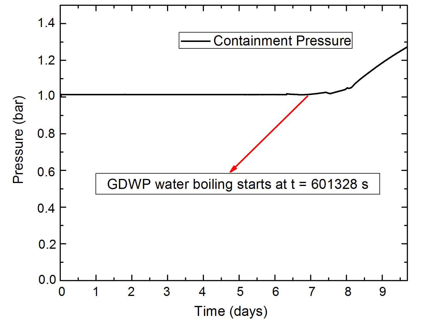
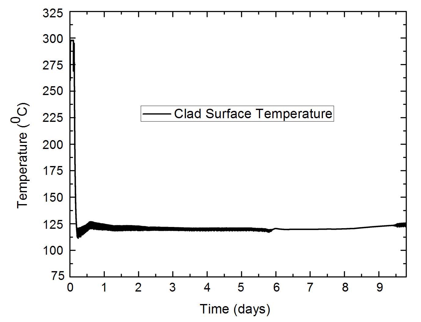
It can be seen that due to the huge inventory of water in GDWP, it is possible to remove the decay heat only with the sensible heating of the GDWP water for nearly 10 days. Figure 23 shows the GDWP temperature rise. With boiling of GDWP water, decay heat can be removed for many more days. However, with boiling of GDWP water, the containment pressurization takes place that may require venting. Containment pressure evolution is shown in Fig. 24. It may be noted that during such a case, the containment can be vented without any impact on the public, as there is no activity release in the containment. The maximum clad surface temperature during the accident is found to be 575K (Fig. 25), which is well within the safety limits.
The above analysis reveals that due to the integration of many passive systems to meet the fundamental safety functions, AHWR design can withstand the multiple failures without compromising the fuel integrity, and hence any radiological impact onsite as well as offsite. The progression of the accidents also reveals the simplifications brought in the design by the passive systems. Various enabling features that make the system cope with major severe accidents may be identified as:
Negative void reactivity coefficient
Limitation on inadvertent reactivity insertion rate
Natural circulation for core heat removal
Passive decay heat removal through ICs
Passive emergency core cooling system
Use of passive valves and rupture disks
Presence of a large heat sink at high elevation inside containment in form of GDWP
Protection against malevolent act by use of passive poison injection to ensure safe shutdown in the very unlikely event of failure of both the shutdown systems