With rapid development of the electronics industry, especially in the areas of personal computers and mobiles phones, the problem of electromagnetic interference (EMI) is increasing. One effective technique to address the EMI problem is to enhance the electrical conductivity of plastics by incorporating conductive fill ers in the polymer matrix. Polymers generally are transformed to electrically conductive composites by either coating or compounding with conductive fillers, such as high electric conductivity fibers [1-6].
To increase the electrical conductivity of fibers, various metal coating techniques can be applied, such as, metal foil, conductive paint, sputter coating, vacuum deposition, flame, and electroless plating. Among them, electroless plating is generally the preferred means of obtaining a conductive filler for EMI shielding. This technique has advantages such as coherent metal deposition, excellent conductivity and shielding effectiveness, and applicability to non-conductors and can be applied to almost all fiber substances [4-8].
During electroless plating, fiber surfaces are metalized during exposure to plating solutions, coating molten salt in the presence of a reductant. The metal plating process is based on a redox reaction in which the reducing agent is oxidized and Ni2+ ions are reduced on the substrate surface. The first layer of deposited nickel serves as a catalyst for the process. As a result, there is typically a linear relationship between the coating thickness and time [5,7-10].
The objective of this study is to apply electroless nickel plating to the preparation of high conductive PET ultra-fine fibers and investigate the effects of electroless Ni-plating on the surface properties and electrical conductivity of PET ultra-fine fibers.
[Table 1.] Composition and operating conditions of electroless Niplating bath
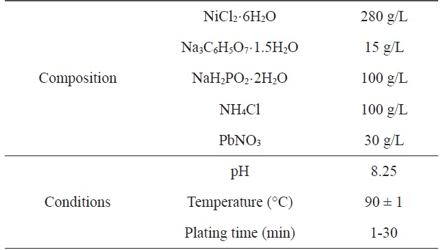
Composition and operating conditions of electroless Niplating bath
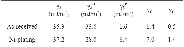
[Table 2.] Variation of the surface free energy by electroless Niplated PET ultra-fine fibers

Variation of the surface free energy by electroless Niplated PET ultra-fine fibers
The fibers used in this work were polyethylene terephthalate (PET) fiber 130d/48f (Island-In Sea Type
Alkali hydrolysis of PET fibers was accomplished by using NaOH (1 N, 80℃, 120 min). The electroless nickel plating was deposited on PET ultra-fine fiber of 10 cm length using nickel chloride as the source of nickel and sodium hypophophite as a reducing agent.
A two-step pretreatment consisting of sensitization and activation was used to catalyze the PET ultra-fine fibers. The sensitizer and activator were stannous chloride/hydrochloric acid and palladium chloride/hydrochloric acid, respectively, which assisted with the formation of a nucleus to plate the metal onto the surface of the PET ultra-fine fibers. The sensitized PET ultra-fine fibers were added to the solution containing the reducing agent. Nickel chloride was used as the source of metal ions, sodium hypophosphite was the reducing agent, and sodium citrate was used as a complexing agent to control the pH of the bath during the plating process. The electroless plating was performed on a hot plate with a magnetic stirrer while maintaining the temperature of the bath at 60 ± 2℃. Samples were prepared at different plating times: Ni-5, 5 min; Ni-10, 10 min; Ni-20, 20 min; Ni-30, 30 min. Table 1 lists the composition and conditions of the Ni plating in this work.
Wide-angle X-ray diffraction (XRD) patterns of Ni-plated PET ultra-fine fibers were obtained with a Rigaku Model D/MAX-III B diffractometer equipped with a rotation anode and CuKα radiation (λ = 0.15418 nm) as the source for measuring the interlayer spacing, d(002). Changes in the surface morphology
of Ni plated PET ultra-fine fibers were examined using scanning electron micrographs (SEM, JEOL JSM-840A).
The four-point method was used in the measurement of the conductivity of fiber bundles. Fiber bundles were cemented with silver paint to Pt leads that were printed onto an alumina plate. Silver paint was used in an effort to minimize measurement error. The electric resistivity of the PET ultra-fine fibers before and after Ni-plating was determined by measuring the volume resistivity using a digital multi-meter (MCP-T610, Mitsubishi Chemical Cooperation of Japan). The measuring room was maintained at a temperature of 25 (±2℃) and a relative humidity of 55 (±2%).
The contact angle was used as a parameter to characterize the wetting performance and surface free energy of the Ni-plated PET ultra-fine fibers. Contact angle measurements of PET ultrafine fibers were performed using a Kruss Processor Tensionmeter K100 with a fiber apparatus. Two grams of carbon fibers was packed into the apparatus, and then mounted indirectly to the measuring arm of the microbalance. The packing factor of the fibers was measured for each continuous filament by measuring the increase in weight per unit time at zero depth of immersion of a completely wetting test liquid (n-hexane). The wetting liquids used for contact angle measurements were water, diiodomethane, and ethyleneglycol. The surface free energy and the London dispersive and specific components of the fibers studied for the wetting liquids are listed in Table 2.
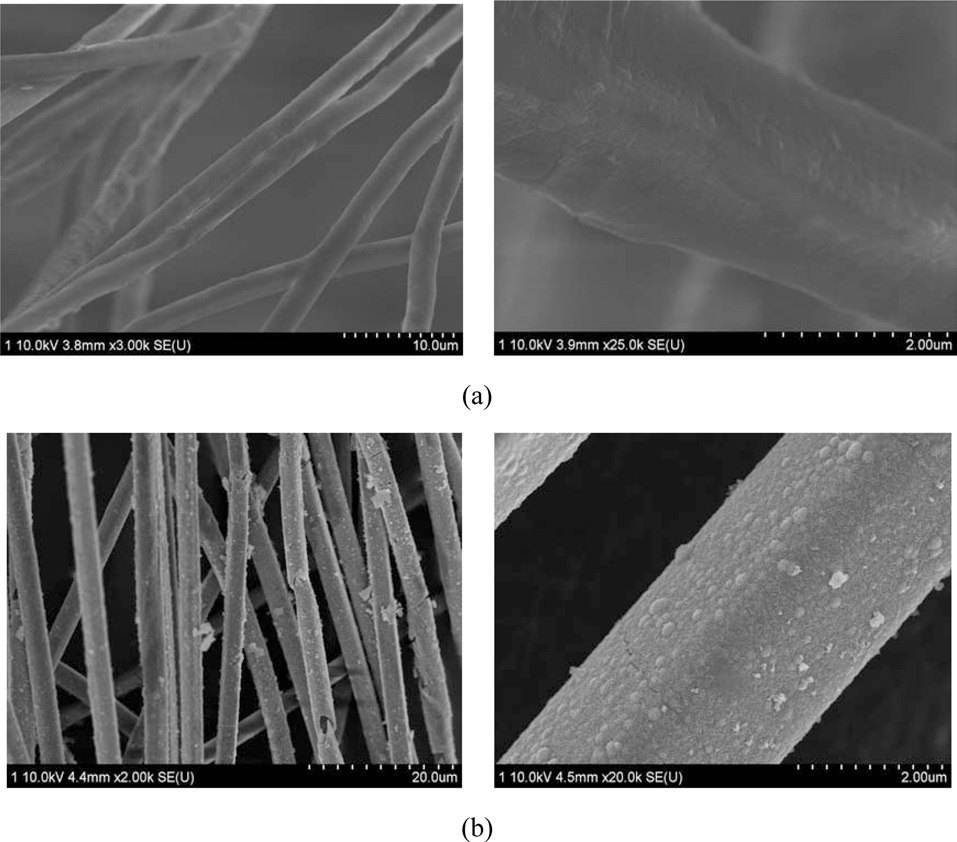
Fig. 1a shows SEM photographs of PET fibers. The as-received PET fibers had uniform diameters. Fig. 2b displays a SEM image of PET fibers after hydrolysis with NaOH. Completely separated fiber can be observed.
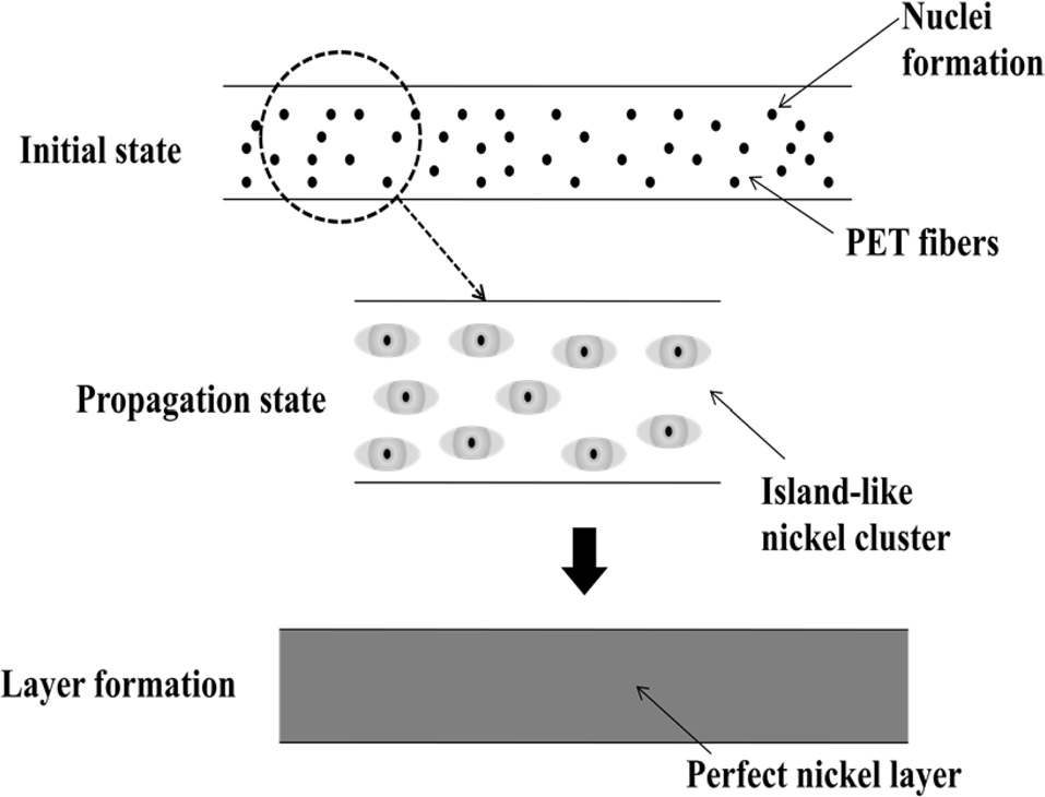
Fig. 2 schematically illustrates the formation of nickel layers on PET ultra-fine fibers. Normally, electroless plating is achieved through the following three steps: 1) initial step: introduction of nuclei, 2) propagation step: formation of Ni islands, 3) layer formation step: formation of a perfect layer.
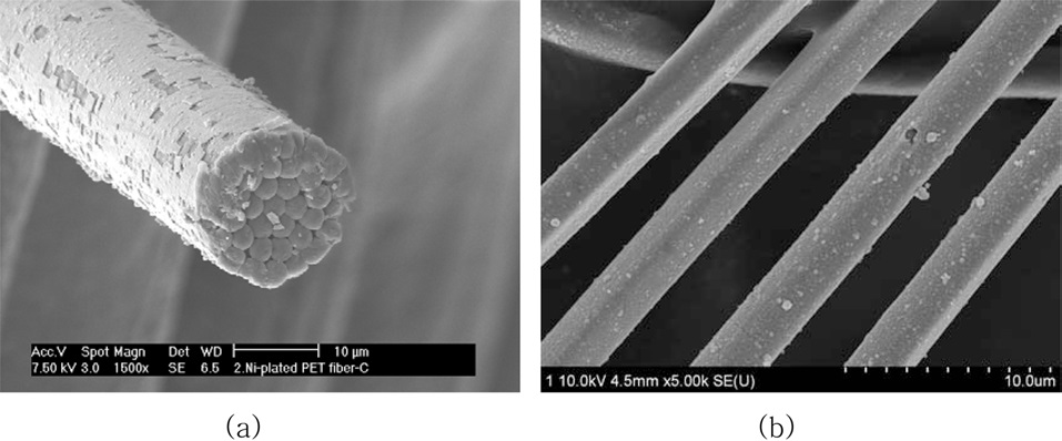
Fig. 3a shows SEM micrographs of the as-received PET ultra- fine fibers, revealing a smooth surface. Fig. 3b displays SEM images of Ni-plated PET ultra-fine fibers after 30 min. It was found that a perfect Ni-layer formed and fully covered the PET ultra-fine fiber surfaces.
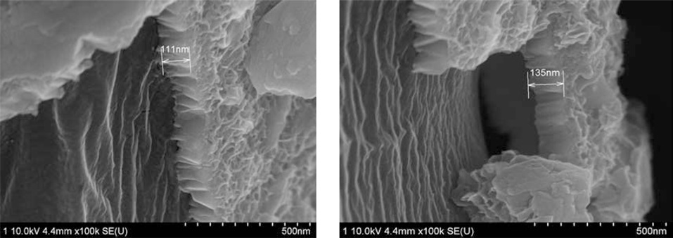
Fig. 4 shows the thickness of the Ni-layer on the PET ultra-fine
fibers as a function of the electroless plating time. This figure shows that the thickness of the Ni-layer increases with an increase in the plating time. The behavior of the thickness of the Ni-layer is in a good relationship with that of the plating time.
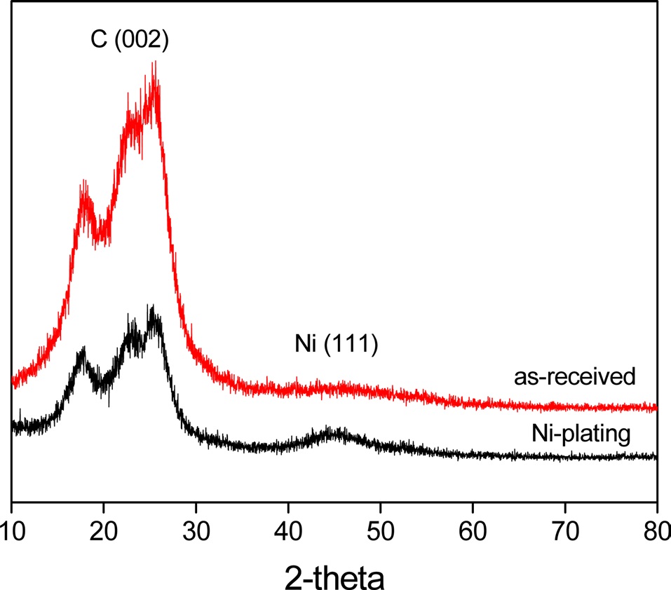
Fig. 5 shows the XRD patterns of Ni-plated PET ultra-fine fibers. It was found that the Ni(111) peak increased when the
fibers were plated with nickel. Meanwhile, the decrease of the C(002) peak upon plating the fibers with nickel indicated that metallic nickel formed a perfect layer and covered the outer surface of the PET ultra-fine fibers.
It is well known that precise contact angle measurement on fibrous materials is difficult, although several methods have been proposed. When a porous material, e.g., a powder of gel, is placed in contact with a liquid of lower surface tension, the liquid rises through the pore system with a velocity that is related to the mean size of the pores, as well as the surface tension and viscosity of the liquid. The relation between these quantities is given by the Washburn Eq. (1):
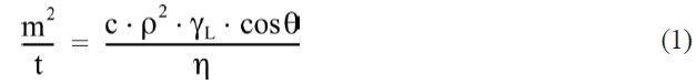
where ‘m’ is the weight of the penetrating liquid, ‘t’ the flow time, ‘c’ the packing factor, and ‘ρ’ the density of measuring liquid. ‘γL’ is the liquid surface tension and ‘η’ is the viscosity of the liquid.
The contact angles of non-treated and nickel-coated PET ultra-fine fibers were measured by three test liquids, water, diiodomethane, and ethylene glycol. In addition, the surface free energy, London dispersive components, and polar components of the PET ultra-fine fibers studied are given in Table 2. The polar component, γSp, of the Ni-plated PET ultra-fine fibers is increased. However, the dispersive component γSL is decreased. These results reveal that the surface polarity increases compared to the as-received PET ultra-fine fibers.
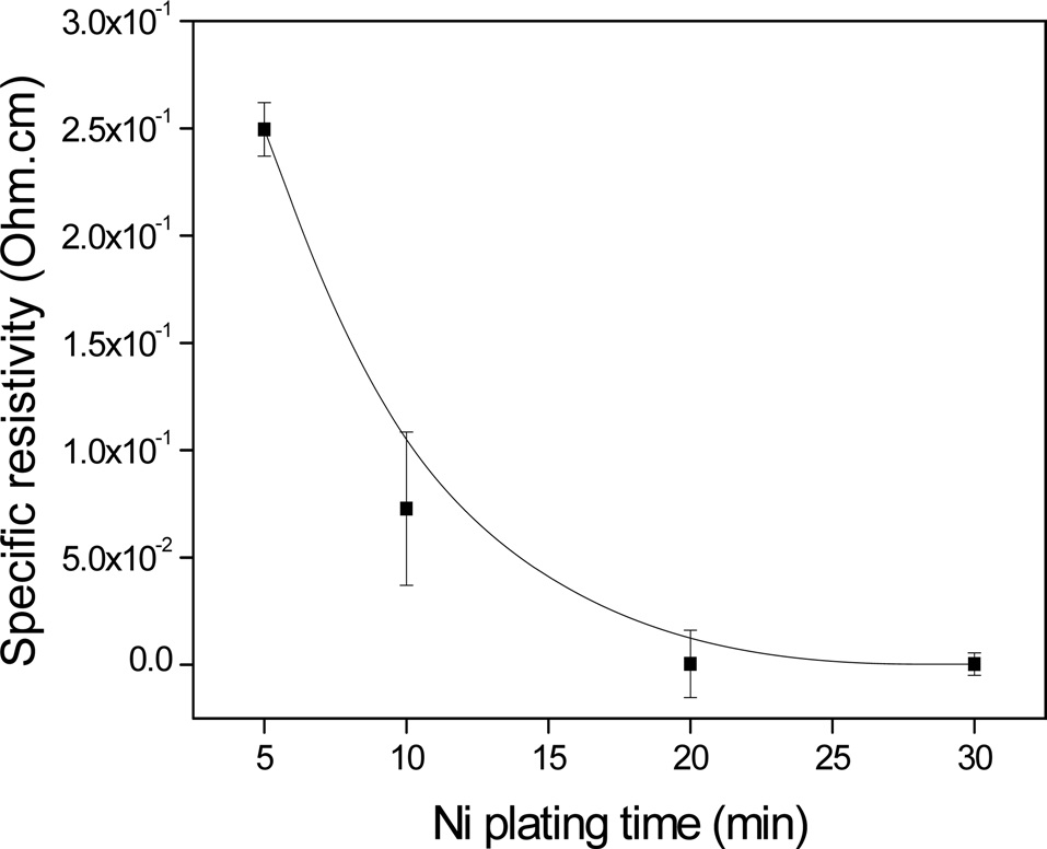
Fig. 6 shows the specific resistivity of the electroless Ni-plated PET ultra-fine fibers with respect to the plating time. It was observed that the electrical conductivity increased with increasing plating time. It was also found that the electric conductivity was significantly enhanced up to 20 min, after which no additional enhancement occurred, up to 30 min. This was most likely due to the formation of perfect Ni layers on the PET ultra-fine fibers after a specific point of the process.
In this work, nickel electroless plating on PET ultra-fine fibers was carried out to improve the electric conductivity of the fibers. The following conclusions can be drawn from this study: 1) the presence of Ni can introduce high electric conductivity to PET ultra-fine fibers; and 2) electrical conductivity of Ni-plated PET ultra-fine fibers increased with increasing plating time and thickness of the Ni-layers.