Single-walled carbon nanotubes (SWCNTs) or CNTs exhibit exceptional physical and mechanical properties which have been drawing significant attention from the academic community as well as industry. For example, SWCNT are 100 times stronger than steel at only one sixth of the weight, and conduct electrical current three orders of magnitude greater than conventional metals [1,2]. In order to utilize these exceptional properties in many promising applications, much effort has been made not only to control and improve the growth of CNTs [3-7], but also to assemble nano-scale CNTs into micro-scale fibers or yarns by direct spinning from chemical vapor deposition (CVD) chambers [8,9] or spinning from CNT forests or carpets [10]. However, once CNTs are assembled into fibers or yarns, their exceptional properties diminish to levels at which CNT fibers or yarns lose their advantages over conventional materials already used in various industries. The main factor in this degradation is that the CNTs composing fibers or yarns possess much shorter lengths than the materials making up typical fibers or yarns, so the properties of CNT fibers or yarns are determined by weak inter-CNTs Van der Waals bonding; not by the intrinsic CNT properties. The obvious way to resolve this problem is to grow meter-long (or even longer) CNTs; then assemble these into fibers or yarns. However, the limited lifetime of nano-scale catalyst particles prevents the growth of long CNTs; whether one meter long or of infinite length. Thus, to understand why catalyst particles are deactivated, so they do not enable continuous growth, is a fundamental issue in the quest to find rational approaches for further improvement in the growth of CNTs.
In the last decade, the lifetime of catalyst particles for CNT growth; and thereby the lengths of CNT forests or carpets, has been improved significantly. By adding small amounts of water vapor to CVD reactors, 2 mm-thick SWCNT forests or carpets were grown in 10 min [3]. Also, even centimeter-long SWCNT forests, or carpets, were achieved by adjusting the gas flow to parallel the direction of the SWCNT alignment [5]. These advances were significant, but are not yet sufficient to take full advantage of the exceptional intrinsic properties available in CNT fibers or yarns. Along with lots of attempts to optimize CNT growth parameters, there has also been a great deal of effort to understand the mechanisms of growth termination. Even though several plausible mechanisms have been proposed (carbide formation of catalyst particles [11], mechanical stresses exerted on the growing array [12], and others), a recent review paper [13] introduced two mechanisms considered the most probable for the termination of CNT growth: carbon over-layer formation [14,15] and dynamic morphological evolution of catalyst particles [16-19]. For the growth termination mechanism by carbon over-layer formation, as CNT growth proceeds, amorphous carbon or a carbon over-layer starts to accumulate on the active catalyst surfaces. In this case, eventually the complete coverage of all active catalyst sites by the excess carbon would lead to termination of CNT growth. On the other hand, for the termination mechanism by evolution of catalyst morphology, the number-density of the catalyst particles continuously decreases during the growth due to Ostwald ripening and sub-surface diffusion, and at some point, this reduction in the number of catalyst particles would lead to growth termination. Also, the structural evolution of alumina around 800℃ and the Brownian motion of catalyst particles were regarded as to potentially affect the growth of CNTs. Both mechanisms are plausible and have experimental evidence. Maybe both mechanisms operate during growth, but depending on the specific growth conditions, just one of them dominates a specific growth process
Here, we present critical, in-situ observations of the termination of individual CNT growth that strongly support the termination mechanism by dynamic evolution of catalyst particles. In-situ observation of CNT growth processes using an environmental-cell transmission electron microscope (E-TEM) lead us to clearly understand that the shapes and sizes of catalyst particles dynamically change at even lower temperatures than conventional growth temperatures used in thermal CVD experiments, and that this change has critical impacts on the termination of growth. In addition, we demonstrate that the growth termination mechanism by evolution of catalyst morphology works not only for base-growth mode, in which catalysts are located between CNTs and their support-layer, but also for tip-growth mode, in which catalysts are located at the growing CNT-tips. This makes it possible to extend the growth termination mechanism by evolution of catalyst morphology to growth methods other than CNT forest or carpet growth, for example the floating-catalyst CVD method, which do not use any supporting layer or substrate.
2.1. Environmental-cell transmission electron microscope
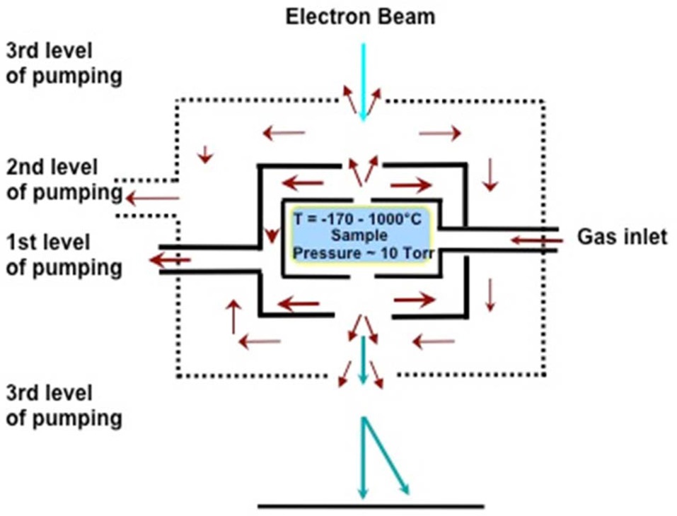
An E-TEM (FEI 80-300 S/TEM Titan) was used for all annealing and growth experiments performed in this work. Compared to conventional high-vacuum TEM, a set of differential pumping apertures inserted above and below the objective lens, and extra turbo-molecular pumps attached to the E-TEM column, allow a very small volume around the TEM sample to be maintained at up to 10 Torr of gas pressure; while keeping pressure
as low as ~10-9 torr in the field-emission gun part. This ETEM configuration enables 0.2 nm resolution for observation of CNTs growing inside the E-TEM. Fig. 1 shows the schematic of the differential pumping system, and describes how differential pumping works. A set of differential pumping apertures play the important role of reducing the conductance of the reactiongases. Then the turbo-molecular pumps dynamically evacuate the reaction-gases between the differential pumping apertures. Thus, the reaction gas pressure is maintained locally around the TEM sample. Reaction temperature is controlled by the singletilt environmental heating stage (Hummingbird Scientific). A 2.3 mm TEM sample is loaded onto the heating stage and the temperature increased by resistive heating around the sample.
For base-growth mode, a 10 nm-thick, Al2O3 support-layer was deposited on a silicon wafer at the rate of 0.2 nm/s; then a 0.5 nmthick Fe catalyst-layer was deposited at the rate of 0.05 nm/s; by e-beam evaporation. For tip growth-mode, only a 0.5 nm-thick Fe catalyst layer (without an Al2O3 support-layer) was deposited on a 500 nm-thick SiO2 wafer; in the same way as the base growthmode sample. For TEM sample preparation, the catalyst layer deposited on the silicon wafer was cut into 2.3 mm disks by an ultrasonic cutter and then the non-deposit side of the sample was hand-polished and dimpled down to ~10 μm thickness at the center of the sample. Finally, the dimpled sample was loaded in the Gatan PIPS and ion-milled from the dimpled side at a 4.5° angle and with 4.5 kV Ar ion beam acceleration voltage. Ion-milling stopped as soon as a small hole appeared at the center of the sample.
The as-prepared TEM samples, with catalyst layers deposited by e-beam evaporation, were loaded into an environmental heating stage. Then, this stage was directly loaded into the E-TEM. H2 gas was streamed until reaching a designated cell pressure; then the heating stage was ramped up to various temperatures (510-680℃). Usually, it takes 10-15 min for samples to stabilize
thermally and thus not drift too much, so the video-recording of annealing or growth experiments was started after 15 min. In-situ CNT growth was initiated by adding 2.5 mTorr of C2H2 gas to the H2 ambient. Annealing and growth processes were recorded by a Tietz off-axis camera at a frame size of 1024 × 1024 pixels2 and frame rate of 12-13 frames per second.
3.1. In-situ annealing experiment in H2
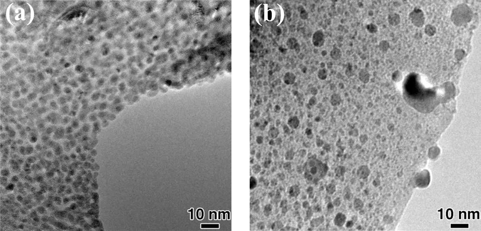
Prior to in-situ CNT growth, an annealing experiment in the H2 ambient was performed in order to reduce the Fe catalyst particles. However, high temperature annealing in H2 before CNT growth may lead to severe catalytic particle coarsening, resulting in very poor yield of CNT growth [20]. Fig. 2 shows TEM images of Fe catalyst particles before and during in-situ annealing for 10 min at 680℃ and 2 torr of H2. As shown in Fig. 2a, the as-prepared TEM sample had well-distributed catalytic particles with sizes of 3-6 nm; which seem to be appropriate for CNT growth. However, some catalytic particles in Fig. 2b are already bigger than 10 nm after annealing for 10 min, indicating that coarsening occurs very fast even at 680℃. This temperature is not quite as high as that of the conventional CNT-growth temperature used in thermal CVD. This severe coarsening before initiation of growth is one of the reasons why, in some cases, fast insertion of the sample into the CVD furnace is critical for efficient SWCNT carpet growth [7].
In order to reduce the catalysts but not cause too much coarsening, the temperature of 510℃ was utilized for annealing in the H2 ambient. Usually, the sample was annealed in H2 for 30 min prior to in-situ CNT growth. A series of images extracted from the movie (Fig. 3) demonstrates that the shape of a catalytic particle evolves dynamically even at 510℃ and 7.5 mTorr of H2. The shape of an Fe particle changed from facetted to rounded (Figs. 3a and b), and from rounded to facetted (Figs. 3c and d). The pretreatment conditions (i.e., temperature, types of carrier gases, and annealing time for catalyst particles) before the beginning of CNT growth make a big difference in catalyst morphology. The facetted or rounded shape of a catalytic particle is highly relevant to the coarsening behavior of catalyst particles, and the resultant shapes and size-distribution of catalyst particles are very influential on CNT-structure (known as chiralities) as well as on CNT yield [21]. Therefore, the evolution of catalyst
morphology is very critical factor for fully understanding the growth process of CNT. However, it is very difficult to observe the dynamic evolution of catalyst morphology in an ex-situ growth experiment, so in-situ experiments can play important roles in understanding how catalyst particles evolve during annealing and growth, and how this evolution affects CNT growth.
In-situ CNT growth was initiated after thermal annealing by adding 2.5 mTorr of C2H2 to the H2 background in the E-cell. The captured images from the video in Fig. 4 show the nucleation and growth of CNT at 650℃ with 2.5 mTorr of C2H2 and 7.5 mTorr of H2. The most interesting feature in this video is the growth of CNT from a catalyst already surrounded by a graphitic- carbon shell. It is one of the well accepted CNT growth termination mechanisms that amorphous carbon over-layers, or graphitic shells, poison the catalysts because they block all active catalytic sites on the catalyst surface, so that hydrocarbon can no longer be decomposed for continuous CNT growth [15]. However, it is clearly observed in this movie that even though a catalyst particle is surrounded by a graphitic shell, it can still nucleate and grow CNT by lifting up the surrounding carbon shell. This observation might be quite relevant to the experimental result in which the hydrocarbon concentration changed from 0.1 to 1% of C2H2 of total process gases but did not critically affect the life-time or activity of Fe catalysts [18,19]. Also, the role of water in extending the life-time of Fe catalysts is claimed to remove the amorphous carbon or carbon shells surrounding the catalyst particles and thus recovering catalytic activity [15], but this observation appears to better support some other mechanism; perhaps Ostwald ripening inhibition, as the role of water in the super-growth of CNT forests or carpets [17].
3.3. In-situ observation of CNT growth termination
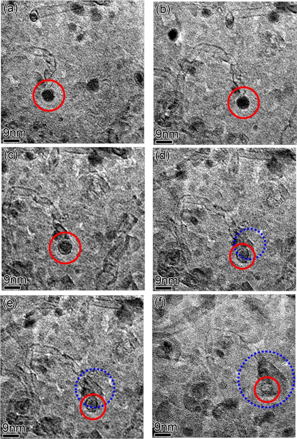
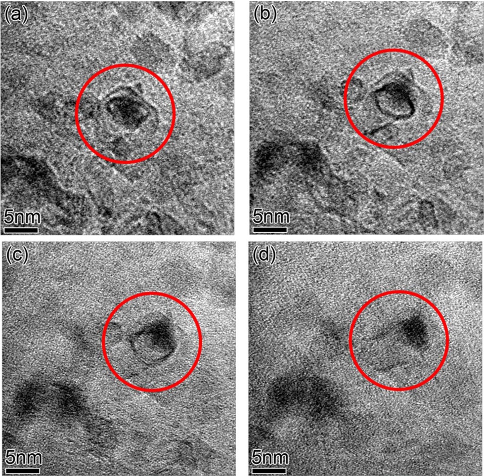
In Fig. 5, in-situ growth; then growth termination of individual CNTs by shrinkage in size and complete dissolution of the catalytic particle attached to the CNT was observed in real time. The catalytic particle in the red solid circle grows the CNT (Figs. 5a-c), and then starts to shrink and stops growing the CNT (Fig. 5c). In Fig. 5d, the catalytic particle attached to the CNT keeps shrinking while a new particle in the blue dashed circle nucleates. From Figs. 5d-f, the particle in the red solid circle completely dissolves and the nucleated particle in the blue dashed circle grows very fast. This is a very interesting observation and cannot be explained by Ostwald ripening. According to Ostwald ripening theory [22,23], particles bigger than a critical size grow, but smaller particles shrink and finally dissolve, therefore minimizing the total surface area of the particles; so the number-density of catalyst particles always decreases. Since the nucleation of new Fe particles on the surface of the Al2O3 layer creates extra surface area, this phenomenon is energetically unfavorable in the framework of the Ostwald ripening theory. Therefore, this should be related to sub-surface diffusion of Fe atoms into the Al2O3 layer, and the diffused Fe atoms inside the Al2O3 layer nucleate new Fe particles in the pores of the Al2O3 layer [18,19]. Al2O3 layers deposited by e-beam evaporation at room temperature have a porous structure [16], so there are enough spaces for Fe atoms to diffuse into. Which one, atomic Fe diffusion into the porous Al2O3 layer or adsorption of Fe atoms onto a large neighboring Fe particle, is more energetically favorable is a topic for further study. In many cases (shown in Fig. 5), the termination of individual CNT growth is not exactly matched to complete dissolution of the catalyst particle. Usually, as CNTs grow, the sizes of catalyst particles shrink
and then the CNTs stop growing. Finally, the attached catalyst particles dissolve completely. There seems to be a range of catalyst particle-sizes which can support continuous growth of CNTs with the same diameter and chirality. Otherwise, defects such as heptagonal or pentagonal carbon rings, should be incorporated into the CNTs to change their diameters or chiralities [24]. The defect formation energy can make changing the diameter of growing CNT by this defects-insertion process unfavorable. Rather, CNT growth just stops when the catalyst particle attached to it changes significantly in size.
In most cases, the CNTs in forests or carpets grow in the base growth-mode; catalyst particles are firmly anchored to the top of a supporting layer and CNTs grow from the anchored catalyst particles. In the tip growth-mode, growing CNTs lift catalyst particles up from a supporting layer, so the particles sit at their tips. Whether CNTs grow in the base growth-mode or tip growth-mode depends on the degree of interaction between the supporting layer and catalyst particles. If the interaction is strong enough, CNTs grow in the base growth-mode, but otherwise, CNTs grow in the tip growth-mode. Strong interaction between the supporting layer and catalyst particles implies that Ostwald ripening would occur very slowly due to slower mobility
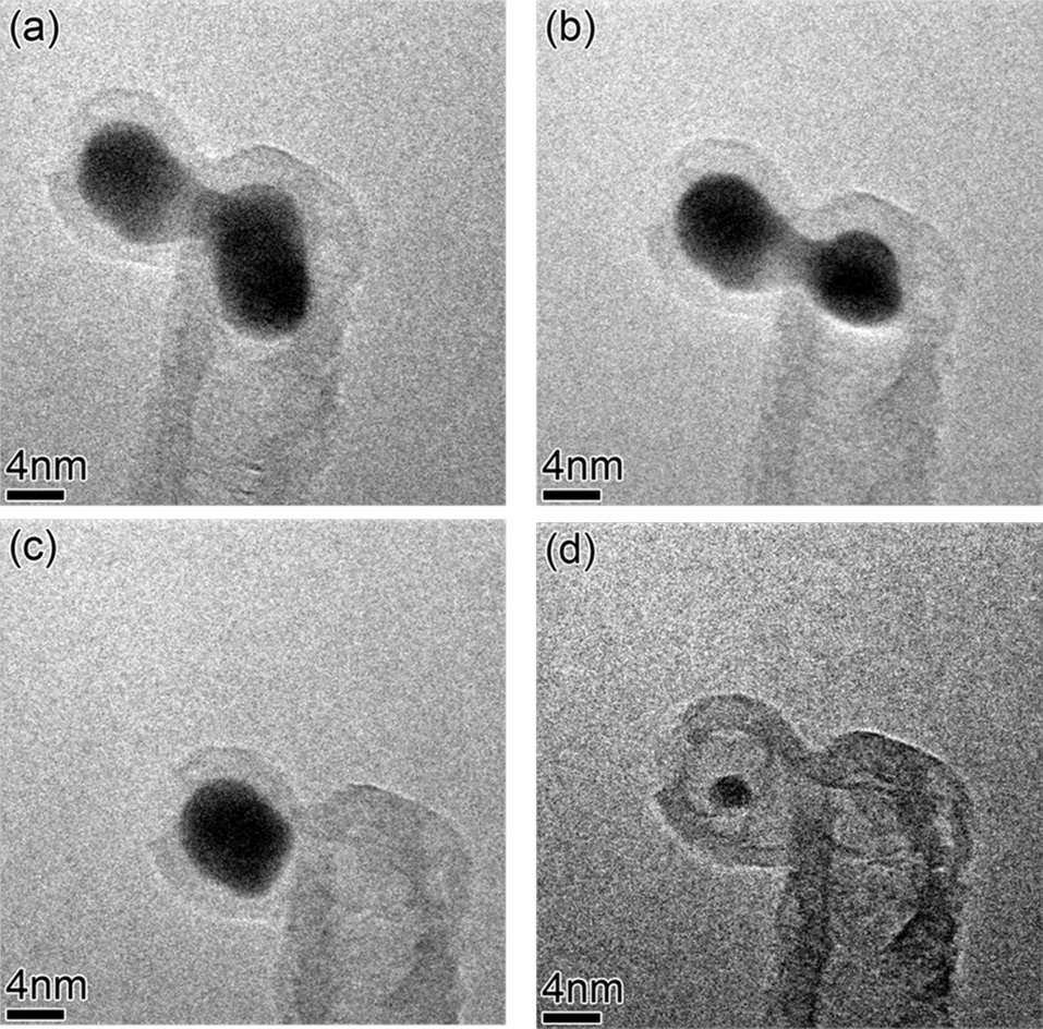
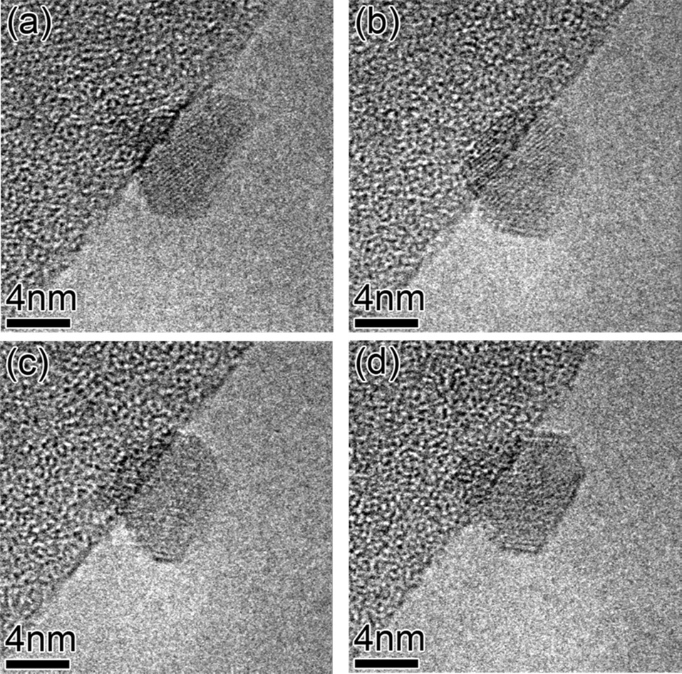
of the catalyst atoms or catalyst particles, so this might be one of the reasons why base growth-mode supports CNT forest or carpet growth. Even though the tip growth-mode cannot support CNT forest or carpet growth, once CNTs grow in the tip growth-mode, inter-particle distances are much greater than those in base growth-mode, so Ostwald ripening among catalyst particles in tip growth-mode might hardly occur. Therefore, it is very interesting to observe catalyst particles at the tips of CNTs evolve in size during in-situ growth. Sequential images extracted from the video (Fig. 6) clearly show that the catalytic particle at the tip of the CNT shrinks in size and completely dissolves. Catalyst atoms might diffuse through the wall of a CNT or the gas ambient to neighboring large particles, but if the growth temperature of 680℃ is considered, diffusion through the wall of the CNT would be favored. However, at relatively high temperatures, evolution of catalyst morphology by atomic diffusion through the gas ambient would be possible. This observation is very meaningful in that it supports the notion that individual CNT growth-termination by evolution of catalyst morphology, could still be valid in floating-catalyst CVD, or high temperature CNT growth methods, in which substrate is not used. Therefore, in any case, either Ostwald ripening or evolution of catalyst morphology needs to be considered as one of the critical factors in CNT growth.
Our in-situ CNT growth experiments strongly support the mechanism in which the morphology of catalyst particles evolves dynamically during pre-treatment and growth stages, and that this evolution may lead to termination of CNT growth. Dynamic evolution of catalyst particles is caused by Ostwald ripening among catalyst particles, and by sub-surface diffusion of catalyst particles into a porous supporting layer. Our observations clearly show that the growth of CNTs can be terminated by the evolution of catalyst particle morphology in both basegrowth and tip-growth modes. Rational design of catalysts to retard such evolution in catalyst particle morphology may lead to extended lifetime of catalysts and thus longer lengths of CNT forests or carpets.