


Silicon carbide (SiC)-based ceramics and their composites (SiC fiber-reinforced SiC matrix composite, SiCf/SiC) have extensively been studied for fusion and advanced fission energy systems owing to their excellent high temperature properties, irradiation tolerance, inherent low activation, and other superior physical/chemical properties [1,2]. Through the development and demonstration of advanced SiCf/SiC composites with a superior neutron irradiation tolerance, the composites have attracted potential applications as blanket structural materials and flow channel inserts in fusion reactors [3-5]. For fission reactors, SiC is being utilized as a coating layer of TRISO particle fuel, and SiCf/SiC composites can also be applied to in-/out of core structural materials, including the control rod sheath and intermediate/process heat exchanger components in high temperature gas-cooled reactors (HTGRs) [1,6,7]. Feasibility studies are also in progress to utilize SiCf/SiC composites as an innovative alternative to metallic materials for fuel cladding of sodium-cooled fast reactors (SFR) [8,9]. In addition, SiCf/SiC composites are considered for fuel cladding and core structures of the liquid salt-cooled advanced high temperature reactor (LS-AHTR) and gascooled fast reactor (GFR) [10-12]. Recently, there have also been efforts to apply the SiCf/SiC composites to the light water reactor (LWR) fuel cladding and guide tubes as well as channel boxes for the fuel assembly of the boiling water reactor (BWR) [13,14]. Compared to the current Zr alloys, the SiC composite cladding will offer a better neutron economy through a reduced neutron absorption crosssection and a higher burn-up. The high-temperature strength of SiC may allow the cladding to operate at higher temperatures and exhibit better mechanical characteristics for pellet-cladding interaction. The SiC composite cladding is also expected to mitigate a vibration induced fretting wear and reduce the hydrogen production during severe accidents [15,16]. In spite of these potential benefits of the composite cladding, there are a lot of technical issues that need to be clarified for the LWR application because the previous research on the SiCf/SiC composite has mostly been focused on high-temperature applications. In this article, we reviewed the fabrication methods of SiCf/SiC composites and material issues regarding the application of SiC composites to LWR fuel cladding. We intended to draw a research direction and highlight important issues to assess the technical feasibility of the SiC composite cladding.
2. FABRICATION AND REQUIREMENTS OF NUCLEAR-GRADE SiCf/SiC COMPOSITES
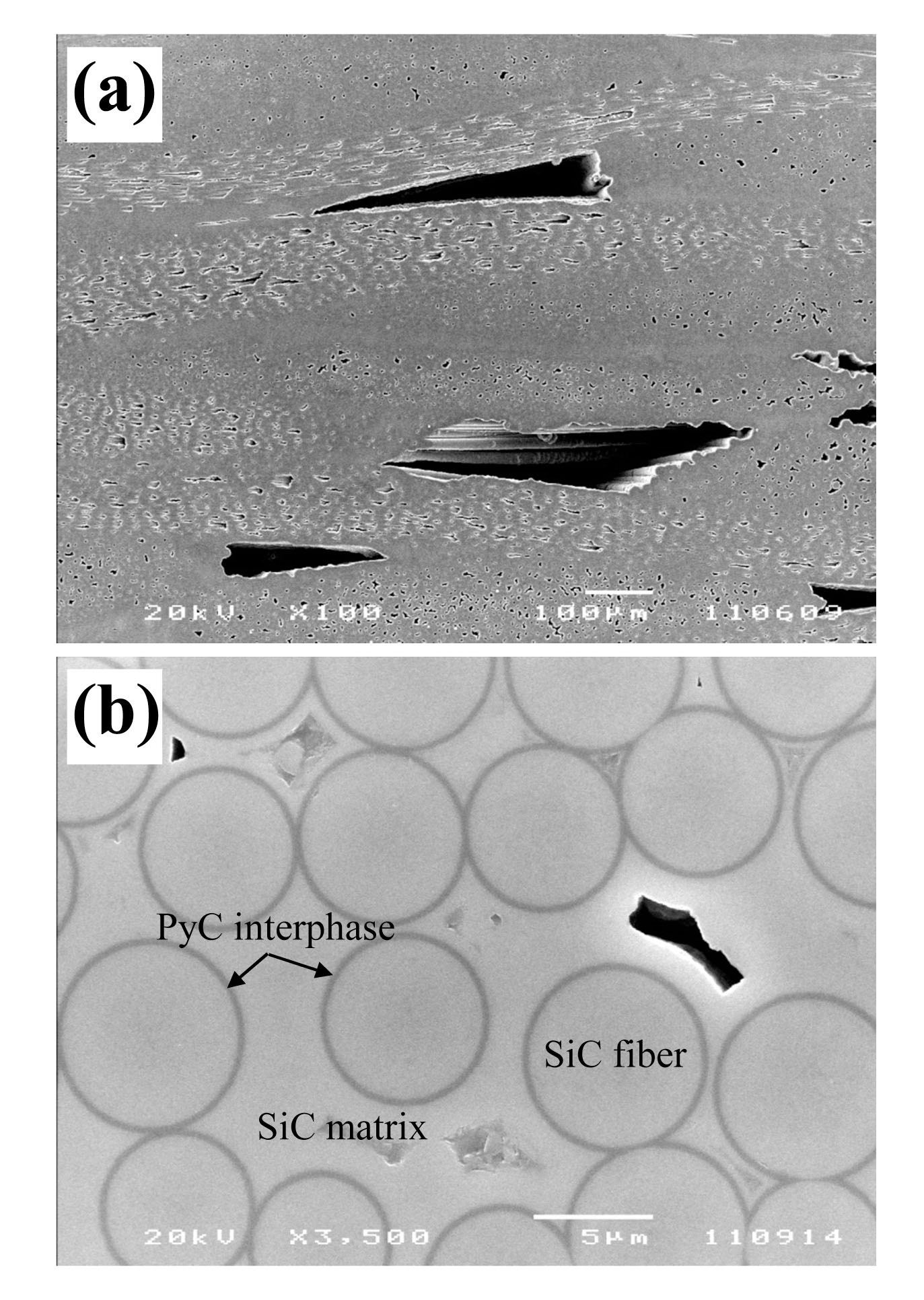
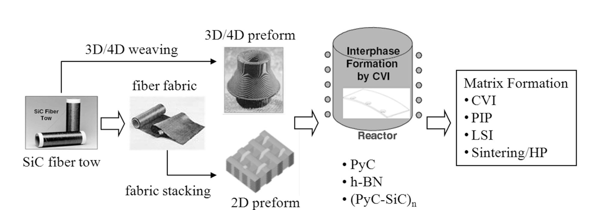
The SiCf/SiC composite consists of SiC fiber, interphase, and SiC matrix of which a typical microstructure is shown in Fig. 1. All three constituents should properly be selected and fabricated to optimize the composite properties for nuclear applications. For the fabrication of SiCf/SiC composites, a SiC fiber tow, a bundle of about a thousand SiC fibers with a diameter ~10 μm, is woven into 2-dimensional
[Table 1.] Typical Features of Third Generation SiC Fibers [18]

Typical Features of Third Generation SiC Fibers [18]
fabric or directly into a multi-dimensional fiber preform as a first step. The fiber preform is then treated in a chemical vapor infiltration (CVI) reactor to coat an interphase material on the fiber surface. The thickness of the interphase is generally controlled to 50-200 nm. The interphase-coated fiber preform is finally processed to form a SiC matrix phase through various methods. A brief description of the fabrication process is given in Fig. 2.
Since the invention of SiC-based fiber in the 1970s, three generations of fine diameter SiC fibers have been developed over the past decades [17,18]. The first and second generation SiC fibers contain a lot of oxygen and/or carbon impurities, which leads to a formation of an amorphous phase and a densification of the fiber by neutron irradiation. As a result, the mechanical properties of SiCf/SiC composites reinforced with the first or second generation SiC fibers are largely degraded even at a neutron fluence of as low as ~1 dpa [1]. On the other hand, the third generation SiC fibers, as listed in Table 1, have a high crystallinity and near-stoichiometric composition. Among the third generation SiC fibers, the Sylramic series are not adequate for in-core structural applications because they contain boron impurities. Therefore, Hi-Nicalon Type S and Tyranno SA3 grades are viable SiC fibers for the fabrication of nuclear-grade SiCf/SiC composites. The advanced SiCf/SiC composites utilizing the Hi-Nicalon Type S fiber have been reported to show little degradation of the mechanical property under a neutron dose of about 40 dpa at 800℃ [4].
The interphase material between the fiber and matrix plays a key role in rendering the composite damage tolerant [19-21]. The interphase has a function to arrest and/or deflect the matrix microcracks, and hence protect the fibers from an early failure, as well as a load transfer [19]. To make the composite damage-tolerant, the interphase material needs to have a layered crystal structure with a low shear strength. In a very limited number of interphase materials satisfying the requirements, pyrolytic carbon (PyC) and hexagonal boron nitride (h-BN) are the best materials. (PyC?SiC)n and (BN?SiC)n multilayered interphases, where the thickness of each layer is typically a few nm or a few 10 nm, are also developed to improve the oxidation resistance of PyC and BN interphases [19]. Among them, the PyC or (PyC?SiC)n interphase would be a viable choice for in-core structural applications.
After the interphase coating, the SiC matrix is fabricated by various techniques such as CVI [22], polymer impregnation/ pyrolysis (PIP) [23], liquid silicon infiltration (LSI) [24], and slurry infiltration/hot pressing (HP) [25,26]. In the CVI process, the SiC matrix is deposited within the porous network of the fiber preform through a decomposition of gaseous precursors such as methlytrichlorosilane (MTS, CH3SiCl3), according to the following reaction.
CH3SiCl3 (g) → SiC (s) + 3HCl (g)
The CVI process yields a SiC matrix with a high purity and crystallinity in spite of its moderate process temperatures (900?1100℃), resulting in composites with a high irradiation and thermal resistance. The CVI technique is also a highly flexible process that can simultaneously accommodate a large number of preforms with different shapes and sizes, yielding near-net-shape parts. However, it requires a long process time and results in composites with significant residual porosity of more than 10%. Therefore, the CVI-processed composite has a relatively low thermal conductivity and poor gas hermeticity.
In the PIP process, the fiber preform is impregnated with a solution dissolved with organometallic polymers such as polycarbosilane (PCS) or polyvinylsilane (PVS), sometimes mixed with SiC filler particles. After curing to make the polymer precursor infusible, the impregnated fiber preform is pyrolyzed at temperatures generally higher than 1000℃. Due to a gas evolution and hence a significant shrinkage of the precursor polymer during pyrolysis, a porous composite is obtained and multiple impregnation /pyrolysis steps of 6?10 times are required to increase the composite density. Nevertheless, in the PIP process, it is difficult to obtain a highly dense composite, and the resulting SiC matrix typically has an inferior purity and crystallinity.
In the case of the LSI process, a matrix slurry comprised of a binder, carbon powder, and SiC filler particles is infiltrated into the fiber preform. After pyrolyzing the binder, the residual porosity is filled with liquid silicon or its alloys by a capillary action at temperatures higher
[Table 2.] Comparison of SiCf/SiC Composite Fabrication Processes [27,28].
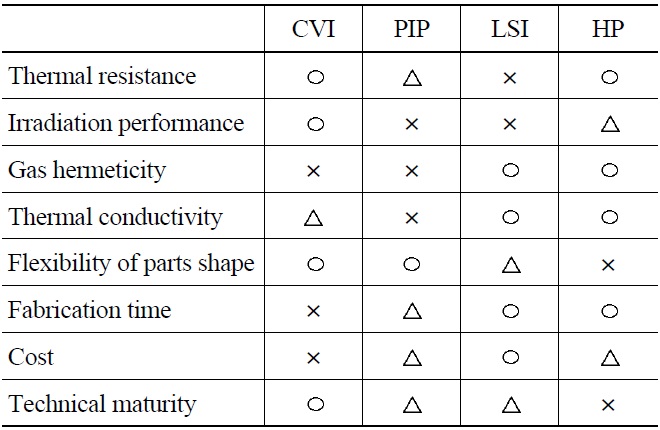
Comparison of SiCf/SiC Composite Fabrication Processes [27,28].
than 1500℃. The infiltrated silicon melt reacts with carbon and produces SiC. The LSI process is a relatively simple process to obtain a high density composite, and therefore yields a composite with a superior hermeticity as well as a high thermal conductivity. However, some amounts of residual free silicon in the matrix are inevitable, making the SiCf/SiC composite inferior in terms of thermal/irradiation resistance.
In the HP process, a matrix slurry, containing a nanosized SiC powder, sintering additives (e.g., Al2O3 and Y2O3), a binder, and sometimes an organometallic polymer such as PCS, is infiltrated into the fiber preform. After drying, the composite is hot-pressed or hot-isostatically pressed (HIP) at temperatures higher than 1700℃ for densification. The SiCf/SiC composite fabricated by this process, for example, the so-called NITE (nano-infiltration and transient eutectic) process [25], exhibits a very low porosity, high mechanical and thermal properties as well as an excellent hermeticity. On the other hand, the HP composite contains residual grain-boundary phases originating from the sintering additives, and more data need to be collected for an assessment of its irradiation performance at high neutron doses. In addition, the process is not so flexible as to fabricate complex shapes, e.g., thin and long tubes. Table 2 summarizes the advantages and drawbacks of the composite fabrication processes mentioned above. The CVI-processed SiCf/SiC composite with PyC or (PyC?SiC)n interphase utilizing Hi-Nicalon Type S or Tyranno SA3 fiber is currently the best combination in terms of the irradiation performance, shape flexibility, and technical maturity.
3. MATERIALS ISSUES OF SiC COMPOSITE FOR LWR FUEL CLADDING
The SiC composite tube for the application of LWR fuel cladding consists of triplex layers as shown in Fig. 3 [13,29]. The innermost layer adopts a high-density monolithic
CVD SiC to render a primary retention of fission products because the CVI-processed SiCf/SiC composite does not have enough gas tightness as mentioned in the previous section. The second layer consists of a SiCf/SiC composite to increase the mechanical properties and prevent a catastrophic failure of the composite tube. Another CVD SiC is finally coated to improve the corrosion resistance of the composite layer. The primary focus of SiC research for nuclear applications has been on high-temperature reactors such as VHTR and fusion reactors. Therefore, the property and performance data of SiC ceramics are rather scarce in LWR environments. Although there would be a number of multidisciplinary issues including fuel/system designs, thermal hydraulics, materials, and so on [10,1530,31], we focus here only on important materials issues that need to be clarified before the deployment of SiC composite cladding.
Generally, SiC ceramics are highly corrosion resistant by forming a protective SiO2 layer in an air atmosphere. However, the corrosion resistance of SiC is largely dependent on the fabrication route and the exact environmental conditions [32]. For example, in a high-temperature and high-pressure water or steam environment, the corrosion resistance of SiC is decreased because the protectiveness of the SiO2 layer is deteriorated [32-36]. Fig. 4 shows surface microstructures of SiC ceramics fabricated by different methods after corrosion tests for 7 days in 360℃ water [33,34]. The test was performed in deionized water with an uncontrolled amount of dissolved oxygen, using a mini-autoclave. The reaction-bonded SiC (RBSC) with a similar fabrication route to the LSI process displayed the worst corrosion resistance. The residual free silicon pockets are severely corroded away and the surface of SiC grains also shows some corrosion. The sintered SiC exhibits a preferential intergranular corrosion and some SiC grains are disintegrated into the water due to the corrosion at the grain boundaries. The CVD SiC ceramics displayed the best corrosion resistance. However, the CVD SiC also
exhibits preferential corrosion at high-angle grain boundaries as shown in Fig. 4(c). Barringer et al. [35] reported the corrosion behavior of CVD SiC in a supercritical water condition (500℃, 25 MPa) with a dissolved oxygen content of 25 ppb. Although they also observed the preferential attack at the grain boundaries, the amount of weight loss was much lower than that reported by the current authors [34] in spite of their higher exposure temperature. They attributed the suppressed corrosion to very low oxygen levels in the water [35].
Henager Jr. et al. [37] reported a pitting corrosion of CVD SiC after long-term corrosion tests up to 5400 h at 300℃ in deoxygenated (< 10 ppb oxygen) high-purity water. They observed that small pits formed within 2000 h of exposure and coalesced into much larger pits with a size of several hundred mm by 4000 h. After an additional 1400 h exposure, the pits disappeared and a uniform corrosion occurred over the surface. Carpenter and coworkers [15,38] also reported the corrosive pitting of the triplex SiC composite tube in a test using an MITR-II LWR simulating test loop (300℃, 10 MPa). For the samples showing pitting corrosion, there were little or no weight losses in the weight measurements [37,38]. Therefore, the corrosion test results should carefully be interpreted along with detailed microstructural observations. Using the irradiation test loop, Carpenter et al. [15,38] uniquely reported the corrosion behavior of the triplex composite tubes coupled with neutron irradiation. They found that the irradiation increased the corrosion rate of SiC and there was a large scatter in weight change depending on the samples. Until now, the exact corrosion behavior of SiC in high temperature water is not clear due to the differences in the test samples and conditions. The kinetics of the SiC corrosion under LWR water conditions, therefore, needs to be defined to confirm the possibility of a burn-up extension and the cost-benefit effect of the SiC composite cladding.
Regarding the steam corrosion under accident conditions, it is expected that the oxidation rate of SiC in hightemperature steam is much lower than that of the Zr alloy. Cheng et al. [39] recently reported the oxidation resistances of several candidate fuel cladding materials at 800°?1200℃ in 1 MPa steam environments. In their experiments, the CVD SiC revealed a much lower oxidation rate at 1200℃ by about two orders of magnitude than the Zircaloy-4. However, a more extensive evaluation of properties such as the mechanical properties and fission products release behavior, etc. in a high-temperature steam environment is needed to define the performance of SiC composite cladding under severe accident conditions.
A technology for end-plug joining with gas tightness should be developed because the SiC ceramics cannot be welded. Several SiC joining technologies have been developed aiming at the application for fusion reactors [1]. Joining techniques considered promising for nuclear applications include diffusion bonding [40], transient eutectic phase joining [41], solid-state displacement reactions [42], glassceramic joining [43], preceramic polymer routes [44], laser joining [45], and selective area CVD [46]. However, a robust joining technology that can be applied to the SiC composite cladding for an LWR has not been proven yet. A monolithic block SiC-SiC joint made by the solid-state displacement reaction using a TiC + Si mixture as a joining material partially survived in the MITR-II irradiation test, where several joints made by the solid-state displacement reaction, diffusion bonding with Ti foil, and CaO-Al2O3 glass-ceramic joining were tested [38]. Considering the configuration and process requirements of the end-plug joining, laser joining would be an adequate technique for applying to the composite tube from the viewpoint of the current authors. However, the selection of proper filler materials would be a key in the technique. The end-plug joint should be both corrosion resistant and irradiation stable while remaining economically feasible, being a great challenge.
The irradiation tolerance of mechanical properties of the advanced SiCf/SiC composite itself has been demonstrated at intermediate temperatures of 500?1000℃ [1,4,47]. Although the irradiation strength data of SiCf/SiC composites are rather limited at relatively low temperatures below 400℃, no appreciable reduction in flexural strength has been reported at 300℃ up to 6 dpa [48-50]. However, the irradiation tolerance of the SiC composite tube in triplex form should be confirmed because stress can develop due to a subtle differential swelling between the composite and monolithic layers. Moreover, the irradiation in LWR water can induce a radiolysis of water molecules and enhance the corrosion of SiC. In fact, the irradiation test in the MITRII LWR simulating test loop showed some degradation in the mechanical properties of the triplex tube at neutron doses below 1 dpa [15,38].
The neutron irradiation induces a swelling of the SiCf/SiC composite and the amount of swelling linearly decreases as the irradiation temperature increases in the pointdefect swelling regime between 150° and 1000℃ [51]. The magnitude of swelling is quickly saturated above 1 dpa and independent of the neutron fluence at irradiation temperatures lower than 1000℃ [49,51]. The volumetric swellings of the advanced SiCf/SiC composite and the CVD SiC have been reported to be saturated at ~1.4 and ~2%, respectively, at the irradiation temperature of 300℃ [49]. This amount of overall swelling is not expected to be a significant issue, but a differential swelling between the inner and outer surfaces of the composite tube or between the monolithic and composite layers can cause a problem as described in the next section.
The high-purity CVD SiC has a very high thermal conductivity above 300 W/m·K at room temperature. The thermal conductivity in a composite form, however, is significantly lower than the CVD SiC for several reasons such as the residual porosity of the SiC matrix, the low thermal conductivity of the PyC interphase parallel to the deposition direction, and the relatively lower thermal conductivity of SiC fibers (65 and 18 W/m·K for Tyranno SA3 and Hi-Nicalon Type S fibers, respectively [18]). The typical room-temperature thermal conductivities of nuclear grade SiCf/SiC composites reinforced with Tyranno SA3 and Hi-Nicalon Type S fibers are about 25 and 10 W/m·K, respectively [52]. The thermal conductivity of the composites is further decreased by neutron irradiation and the magnitude of reduction increases with decreasing the irradiation temperature. The thermal conductivity of the triplex composite tube is expected to be around 3?5 W/m·K after irradiation under LWR conditions [15,38].
The low thermal conductivity of composite cladding can increase the fuel temperature and decrease the fuel safety margin. Based upon a FRAPCON code analysis, MIT researchers have calculated that the average fuel temperature can be up to 280℃ higher than the Zircaloy cladding, and suggested an annular pellet design as one of the measures to increase the fuel safety margin [14,15]. Another consequence of the low thermal conductivity is the generation of secondary stress due to the thermal expansion mismatch between the inner and outer walls of the composite tube. Given the typical fuel power density and fuel rod dimensions, the temperature gradient would be in the order of 100℃ through the wall thickness of the cladding [10,53]. In addition, stress can develop due to the temperature-dependent swelling gradient through the wall thickness [10,11]. Katoh et al. [10] stated that the combination of temperature gradient and differential swelling would lead to ~0.05% elastic strain within the clad wall, implying a finite probability of matrix cracking and it would be problematic to the fission product retention. The secondary stresses generated by the temperature and swelling gradients would interplay with each other in a complex manner and dedicated irradiation programs would be required to uncover the effects.
3.5 Reliability of Matrix Microcracking
The fracture strengths of brittle materials such as SiC ceramics have a statistical distribution, described by the Weibull statistics shown in the following equation [54].
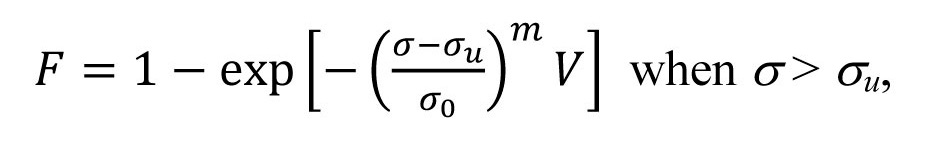
where
The SiCf/SiC composite has an even higher reliability in fracture strength than the monolithic form and shows a pseudo-plastic fracture behavior. The Weibull modulus of the fracture strength of SiCf/SiC composites has been reported to be higher than 20 [56,57]. The microcracking stress of the SiC matrix, however, is significantly lower (< 100 MPa) than the ultimate tensile strength of the composite (250?350 MPa) and shows a large scatter [52,57]. It is reasonable to assume that the Weibull modulus of the matrix microcracking stress would be in the lower bound of the value of the dense CVD SiC because the SiC matrix contains a number of interbundle and interfiber pores as shown in Fig. 1. Therefore, the stress applied to the composite tube should be kept to a very low value to prevent a release of fission products through the microcracks. In the current Zircaloy cladding system, fuel failures have decreased significantly over the past 15 years with a failure rate lower than 10-5 [58]. In order to maintain a fission gas release rate (i.e., the probability of matrix microcracking) below 10-6, the applied stress on the composite cladding should be as low as ~20 MPa if we assume the scale parameter and Weibull modulus of the matrix microcracking stress to be 100 and 8, respectively [59]. It is greatly challenging to manage a thin-walled ~4 m long ceramic composite tube below such a level of applied stresse, a fuel design concept with multiple retention barriers for the fission products needs to be considered as well. From the viewpoint of the fission products retention capability, the fully ceramic microencapsulated (FCM) fuel pellets, in which the TRISO fuel particles are dispersed in a liquidphase sintered SiC matrix, would be a plausible approach [60,61].
There are several manufacturers producing SiCf/SiC composites worldwide and more limited number of companies capable of producing nuclear-grade composites. To the best knowledge of the authors, the current facilities utilizing CVD technology worldwide can produce 1.5?2 m long tubes, and hence an infrastructure should be established for the fabrication of a full length tube. The requirements of strict dimensional control and straightness of the tube are also a challenge for the ceramic composite community. In addition, the high-performance SiC fibers are still very expensive as shown in Table 1 and the fiber cost should be lowered through mass production.
The technology of SiC composite cladding for LWR fuel is at the very early stage of development. Among the various issues described in this review, the corrosion behavior of SiC under LWR condition needs to be clarified above all. For an exact determination of the corrosion behavior, the fabrication of composite tubes with well-controlled properties should be preceded. The development of a robust joining technology for the end-plug and the matrix microcracking susceptibility are significant challenges for the application of SiC composite cladding. In spite of the various technological hurdles, the SiC composite cladding would significantly increase the economy and safety of LWR fuel under both normal and accident conditions if successfully applied. Furthermore, the SiC composites have a wide spectrum of applications ranging from various concepts of advanced fission reactors to fusion reactors. Therefore, long-range development programs including materials development and fuel/system designs are recommended not limited to a single application field.

![Typical Features of Third Generation SiC Fibers [18]](http://oak.go.kr/repository/journal/12598/OJRHBJ_2013_v45n4_565_t001.jpg)
![Comparison of SiCf/SiC Composite Fabrication Processes [27,28].](http://oak.go.kr/repository/journal/12598/OJRHBJ_2013_v45n4_565_t002.jpg)

![SEM Microstructures for the Surfaces of (a) Reaction- Bonded SiC, (b) Sintered SiC, and (c) CVD SiC Ceramics after Corrosion Tests for 7 Days in 360℃ Water [33,34].](http://oak.go.kr/repository/journal/12598/OJRHBJ_2013_v45n4_565_f004.jpg)


