A concrete structure such as a nuclear power plant requires not only an overall evaluation but more importantly, needs to be designed against collision impact as well as against intrusion, penetration, and scabbing to maintain its structural safety and serviceability. A plausible impact can be classified as an external impact or an internal impact depending on the impact location, and as a ductile impact or a stiff impact depending on the magnitude of the deformation of the impacting object. A design resistant against local damage of a nuclear power plant considers major impacting objects, such as the engine of an aircraft, a tornado, or a turbine. An aircraft engine impact is considered a ductile impact, whereas tornado and turbine impacts are considered stiff impacts.
The local damage from an aircraft has been evaluated mainly with respect to the engine of the aircraft. According to a real collision test with an F-4 Phantom [1], the depth of the penetration in the concrete panel at the main body was 20mm, whereas at the engine of the aircraft it was 60 mm. This result is due to the fact that the main body has a relatively large area of collision and shows a large magnitude of deformation, whereas the engine is stiff and has a small area of collision that can lead to major local damage. Tornado impact is another external cause of local damage, which occurs frequently in areas of strong tornado occurrence, and the possibility is about 10?4 ? 10?3, so tornado impact is considered in the design process[2].
A turbine impact is an internal impact that occurs during operation of a nuclear power plant. The rotating part of a turbine generator has large kinetic energy and it can break other stationary parts in the case of mechanical failure.
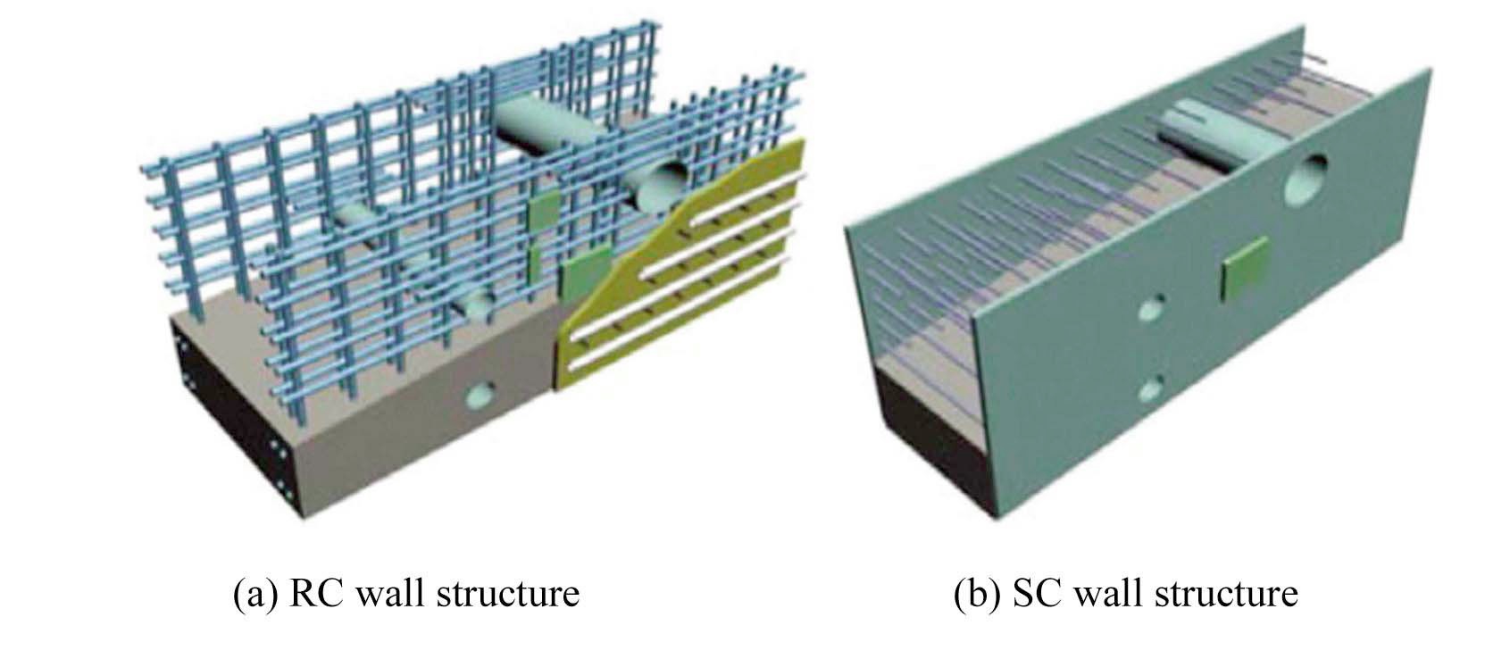
Wall structures of subsidiary buildings have mainly been RC structures up until recent years. However, there has been increasing interest in modular construction to reduce construction time. Modular construction uses the SC (Steel Plate Concrete) wall structure instead of the RC wall structure. Currently, the SC wall structure is installed in non-safety related structures, but in the future, it will be available for safety related structures. Studies on the local damage of RC wall structures have been conducted [3][4][5][6], but those on the local damage of SC structures have only begun recently [3][7]. Kojima [3] performed a local collision test against an RC wall and an RC wall with a linear plate in a containment structure and verified that the linear plate increases the resistance against local collision. Yoo et al [7] performed a local collision analysis against SC wall structures with structural steel and high manganese steel, and found that the manganese steel increases the resistance against local damage dramatically.
This study evaluated the local damage due to an internal turbine impact in the subsidiary structure of a nuclear power plant using the LS-DYNA [8] program for collision analysis. The wall of the subsidiary structure was made of SC structure. Structural steel and high manganese steel with high ductility/energy absorbance were applied to the SC structures for comparison. The effects of collision speed and collision angle, and the material characteristic of the steel of the SC wall, on the local damage due to a local collision were evaluated.
2. LOCAL COLLISION ANALYSIS OF A TURBINE IMPACT
2.1 Inner Surface of the SC Structure of the Exterior wall of a Subsidiary Building
The SC structure of the exterior wall, which was designed according to KEPIC SNG [9], has a total thickness
of 1.524 m. The concrete part is 1.49 m wide and each steel plate is 0.019 m wide. The inner part of the steel plate, where concrete is fixed, has a shear stud every nine inches. The SC structure consists of concrete between two steel plates, as shown in Fig. 1(b). A local collision analysis was performed for the case in which a turbine impact occurred inside and hit the inner part of the exterior wall structure.
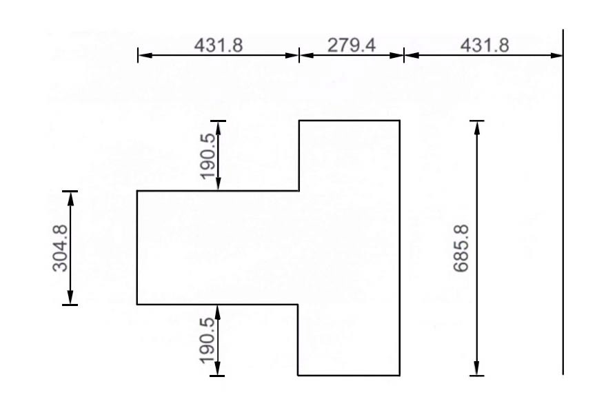
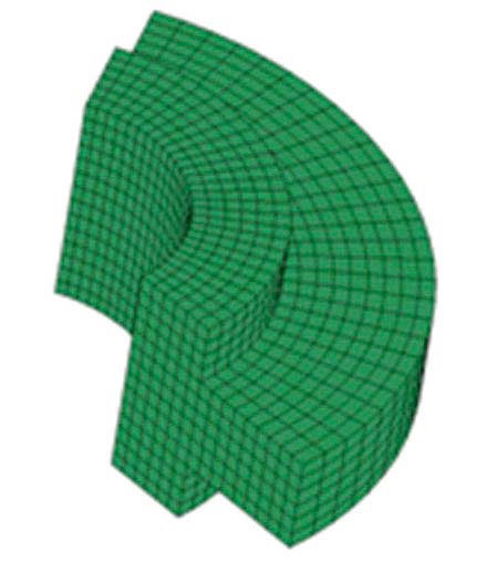
The SC wall structure is a square with 9000mm span and its total thickness is 1524mm, including two steel plates of 19.05mm thickness. The shape of the turbine impacting object is determined based on a previous study [10] and described in Fig. 2 in detail. The finite element model of the turbine object (Fig. 3) is made by a 120 degree rotation of the cross section in Fig. 2 and 8 node cubic elements were used for analysis. The total mass of the turbine is 3750kg.
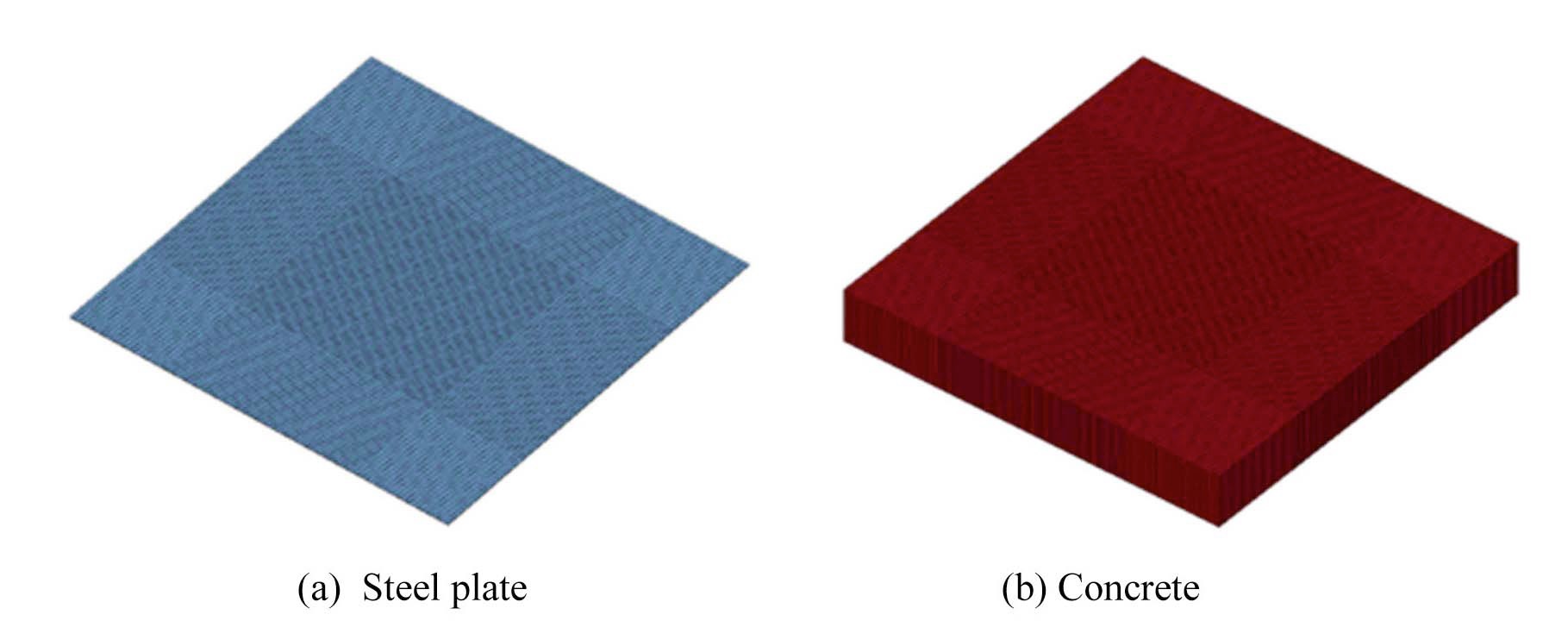
The steel plate and concrete in the SC structure were modeled by 8 node cubic elements. The real SC structure has studs for perfect unification of concrete and steel. However, the studs were excluded in the finite element model for analysis efficiency. Boundary nodes were shared by the concrete and steel parts. Many openings, as shown in Fig 1.(b), are available for the installation of pipes in a
real structure, but are not available in the model. The central part of the SC structure, where the turbine hits, was divided into small elements and the remaining parts were divided into relatively large elements for analysis efficiency. For the contact condition between the impact and target structures, the target element was eliminated when the target element lost its stiffness due to impact for calculation efficiency. The finite element model of the SC structure is presented in Fig. 4 with steel plate and concrete models.
2.2.1 Concrete Model
LS-DYNA[7] has several nonlinear concrete models including CSCM(Continuous Surface Cap Model), the Winfrith model, and the Concrete Damage Rel.3 model, which have input parameters of compressive strength, tensile strength, and Poisson’s ratio. Chung, et al [5] performed numerical analyses of a collision test using those 3 models of LS-DYNA and compared the results with real experiments. The analysis result of the CSCM model was the closest to the experiment results. Based on this finding, the CSCM model was selected for the analysis of the local collision test in this study. Since the impact structure collides with the SC wall structure at 128-198m/sec, the strain
[Table 1.] Material Properties of Various Steels Applied to SC wall
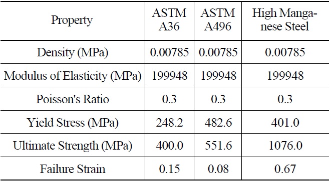
Material Properties of Various Steels Applied to SC wall
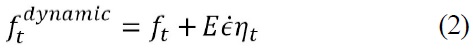
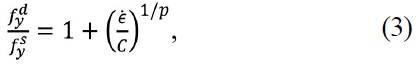
rate hardening effect of concrete was taken into account. When the strain rate increases to 1~10 sec-1, the compressive strength and tensile strength increase up to 20-50% and over 100%, respectively, whereas the elastic modulus remains independent of the strain rate [11,12]. The dynamic compressive and tensile strengths of the CSCM model are described as
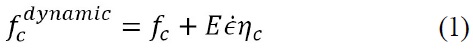
where

is the effective strain rate,
2.2.2 Steel Model
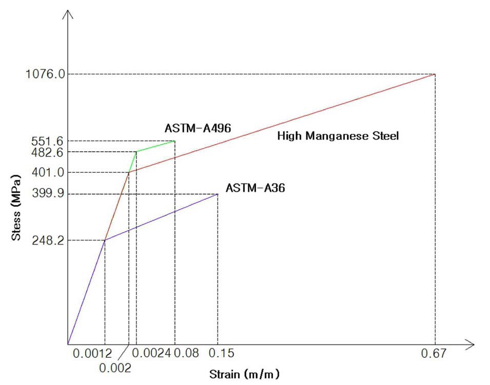
The steel plate of the SC wall structure and the impacting object were modeled using the PLASTIC KINEMATIC steel model, and the strain rate hardening effect presented in the following equation, which was originally proposed by Cowper-Symonds [8], was considered. The parameters
where
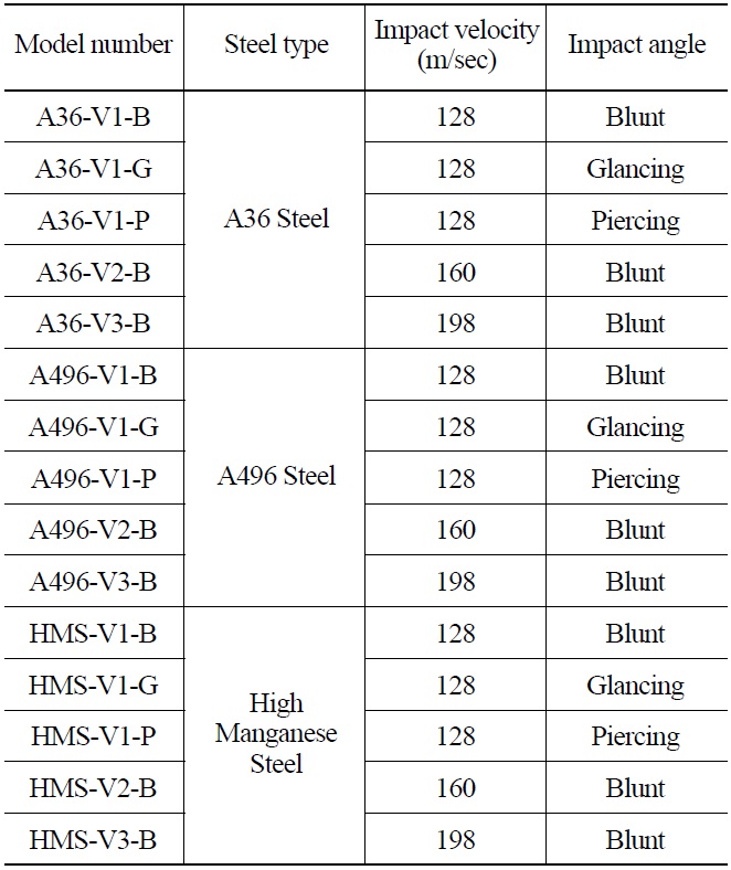
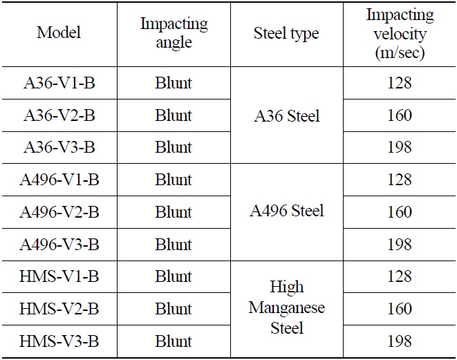
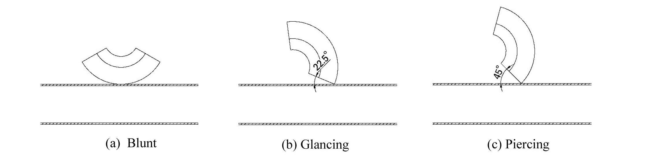
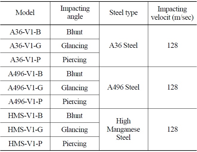
To compare the differences between various steels, impact angles, and impact velocities, each variable was utilized as a parameter of a finite element analysis. The major characteristics of the analysis models are listed in Table 2. The impact velocities and angles are based on a reference [10]. Each impact angle is shown in Fig. 6.
In this study, the differences in local damage for various steels under the condition of same impact velocity and angle, for various impact angles under the condition of same steel type and impact velocity, and for various impact velocities under the condition of same steel type and impact angle, are investigated and compared.
4. RESULT OF THE LOCAL COLLISION TEST BY A TURBINE IMPACT
For the 15 analysis models listed in Table 2, local collision analyses were performed using LS-DYNA. Various
[Table 2.] Main Characteristics of the Analysis Model

Main Characteristics of the Analysis Model
[Table 3.] Collision Analysis Result
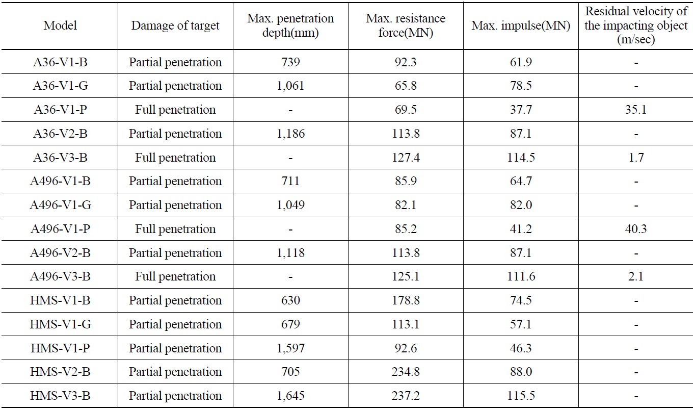
Collision Analysis Result
analysis results including the degree of damage to the target, the maximum penetration depth, the maximum resistance force, the maximum impulse, and the residual velocity of the impacting object are summarized in table 3.
4.1 Evaluation of Local Damage for Various Material Properties
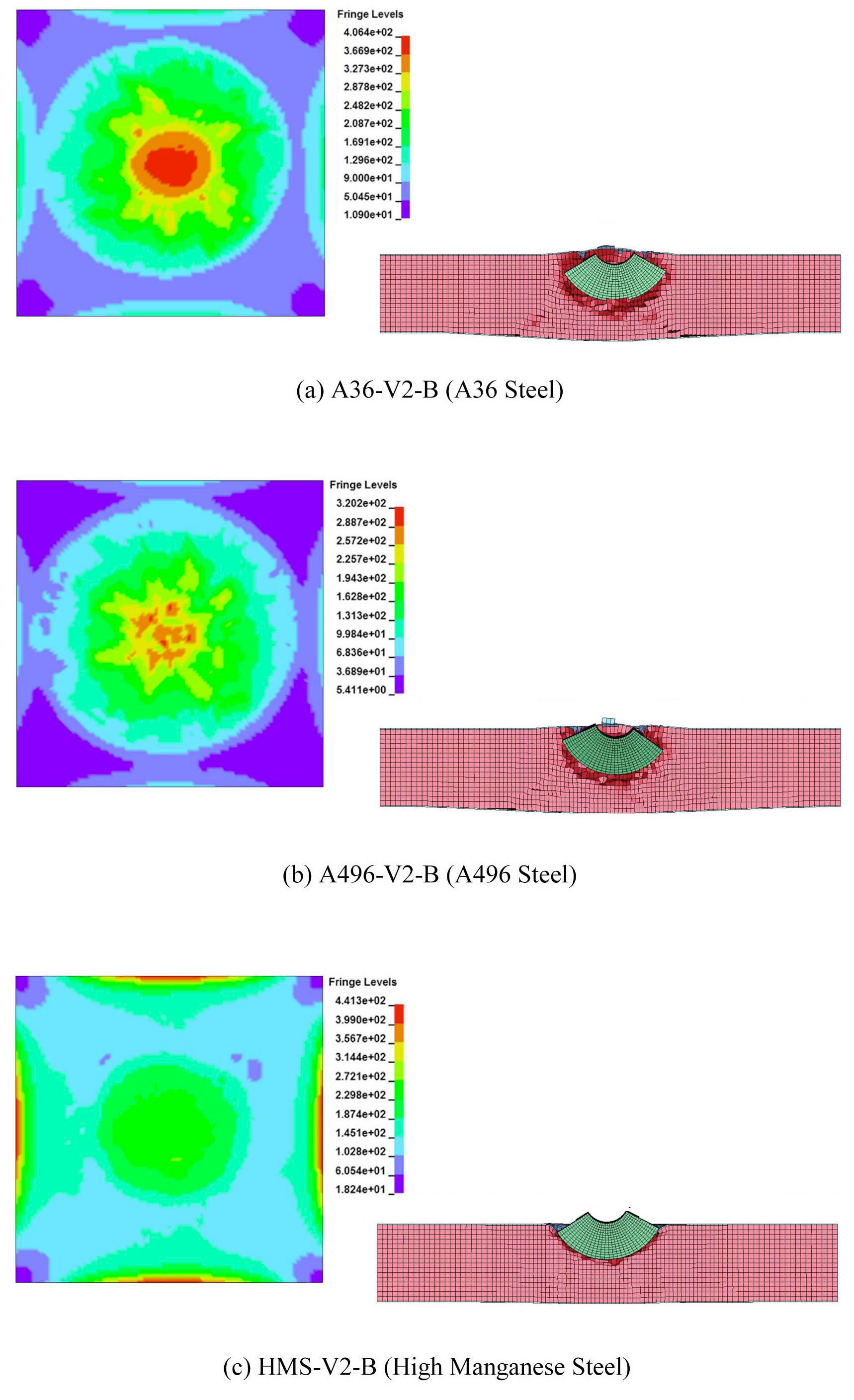
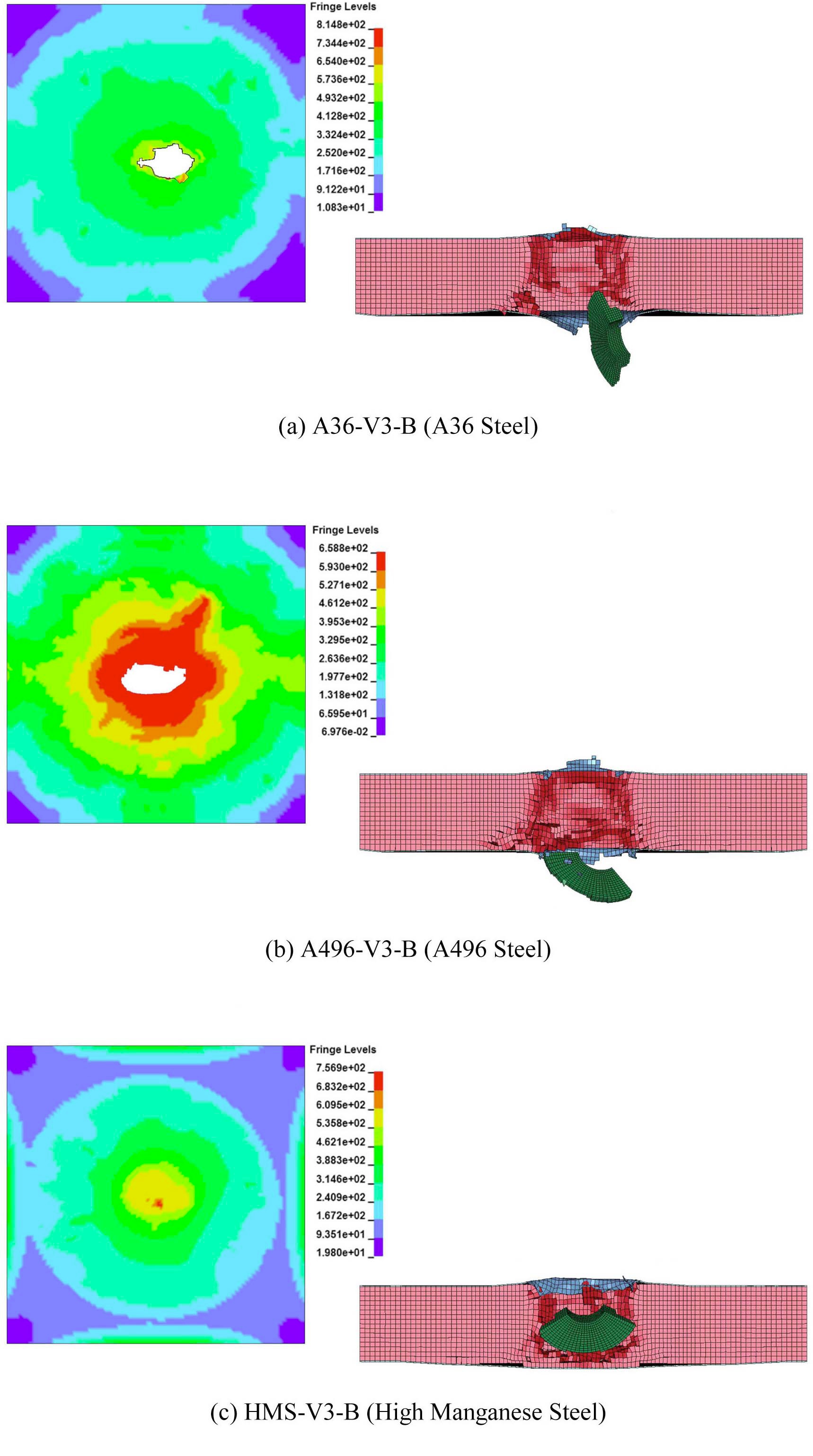
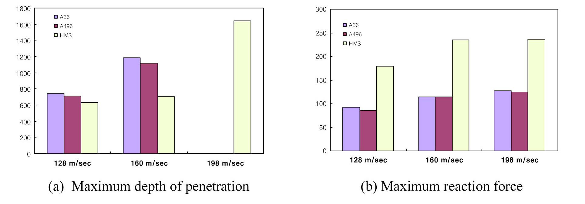
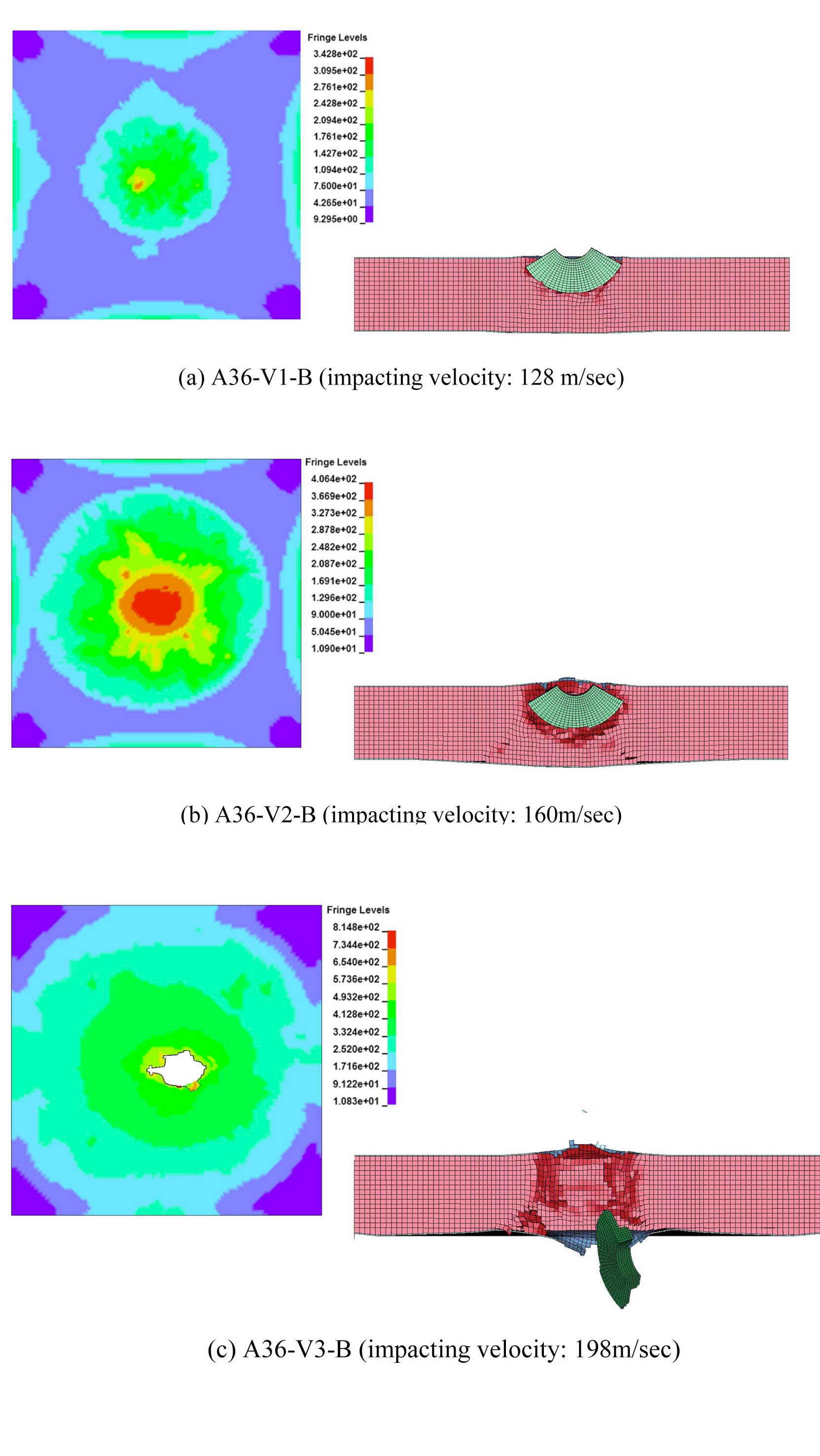
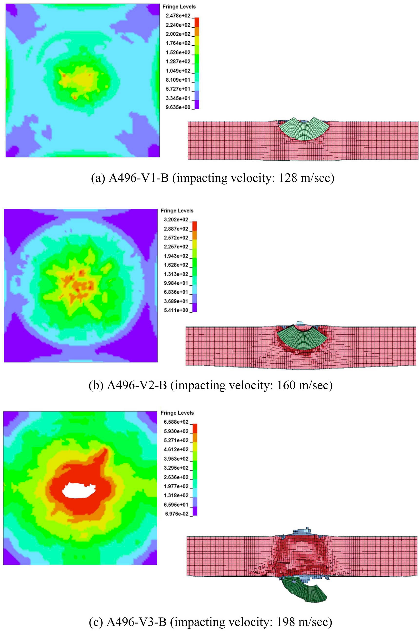
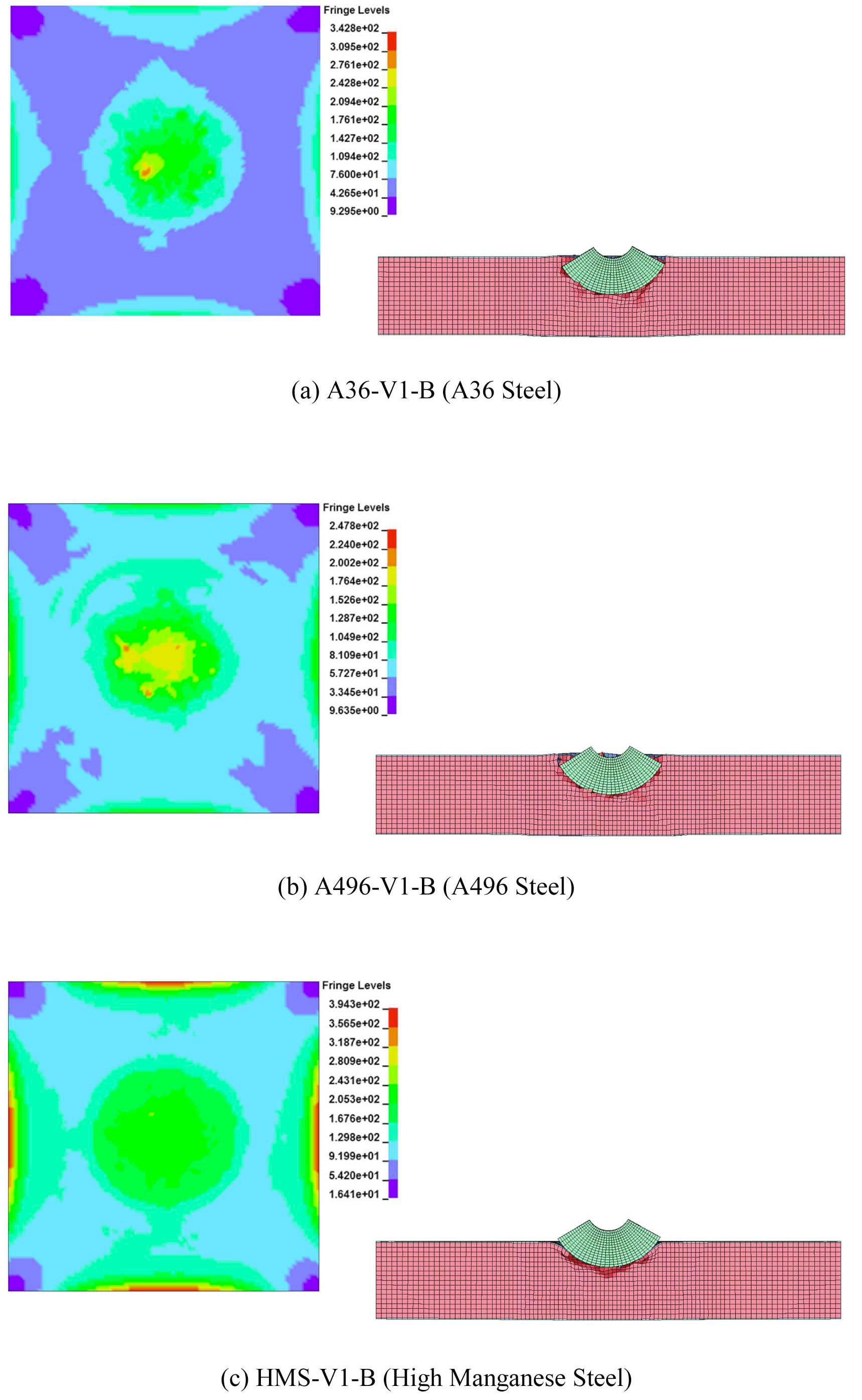
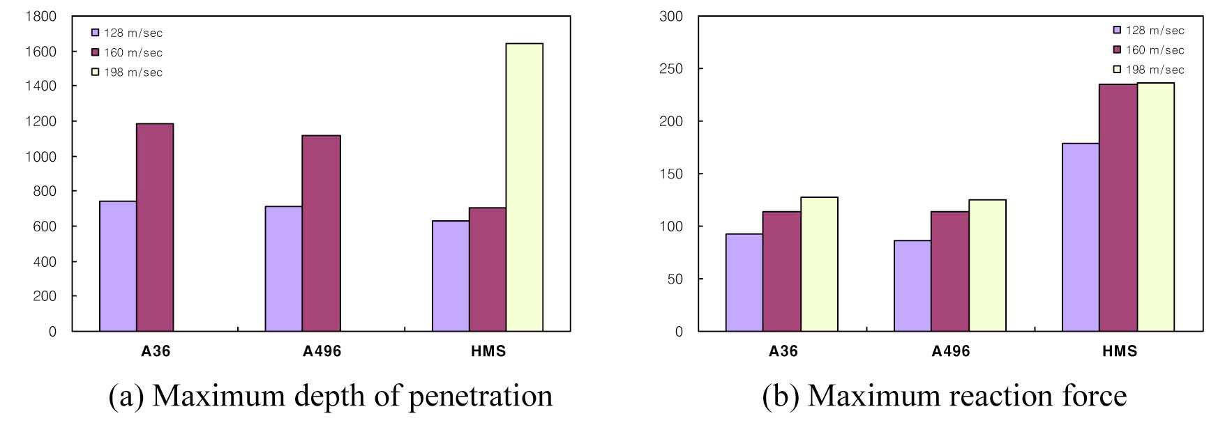
To evaluate the local damage according to steel properties under the condition of a specified impacting velocity and impacting angle, 9 out of 15 models in table 2 were selected and summarized in table 4. The damaged shapes of the back face and side section of each model are listed in Fig. 7 ?Fig. 9. The maximum penetration depth and maximum resistance force of each model are compared in Fig. 10.
For the cases of 128m/s and 160m/s impacting velocities, all models developed partial penetrations (Fig. 7, 8). For the case of 198m/s impact velocity, the A36 and A496 models developed full penetrations, whereas the HMS model developed a partial penetration (Fig. 9).
For the cases of 128m/s and 160m/s impacting velocities, the maximum depths of penetration varied according to the steel properties (Fig. 10(a)). For the 128m/s impacting velocity case, the HMS model (HMS-VA-B) developed a partial penetration, which was 85.3% of the penetration of the A36 (A36-V1-B) model. For the 160m/s
[Table 4.] Model Specification Considering Steel Properties

Model Specification Considering Steel Properties
impacting velocity case, the HMS model (HMS-V2-B) developed a partial penetration, which was 59.4% of the penetration of the A36 (A36-V2-B) model.
These results show that local damage due to an impact is mainly affected by material properties and the differences in local damages are more significant in fast impacting cases.
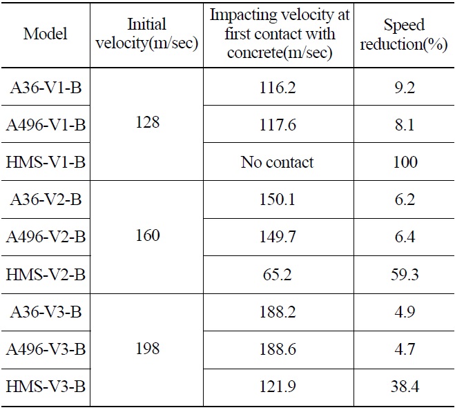
Table 5 presents the velocity decreasing ratio between the velocity of the initial impact on the front steel plate and the velocity when an impacting object hits the concrete after it penetrates the front steel plate. For the 128m/s impacting velocity case, the velocity decrease ratios of A36 and A496 steel are 8~9%, whereas that of HMS is 100% because the impacting object cannot penetrate the front steel plate. For the 160m/s impacting velocity case, velocity decrease ratios of A36 and A496 steel are about 6%, whereas that of HMS is 60%. For the 198m/s impacting velocity case, velocity decrease ratios of A36 and A496 steels are 5%, whereas that of HMS is 40%. Overall, the velocity decrease ratio of HMS is significantly higher than those of the other steel types, which is a characteristic of HMS with high ductility and energy absorbing capability. The impacting object hits the front steel plate first. If the front steel plate is sturdy, it prevents damage of the concrete and the overall damage of the structure. The higher
failure strain and ultimate strength of HMS than those of A36 and A496 steels lead to the high resistance of HMS to an impacting object and thus, less damage to the overall structure.
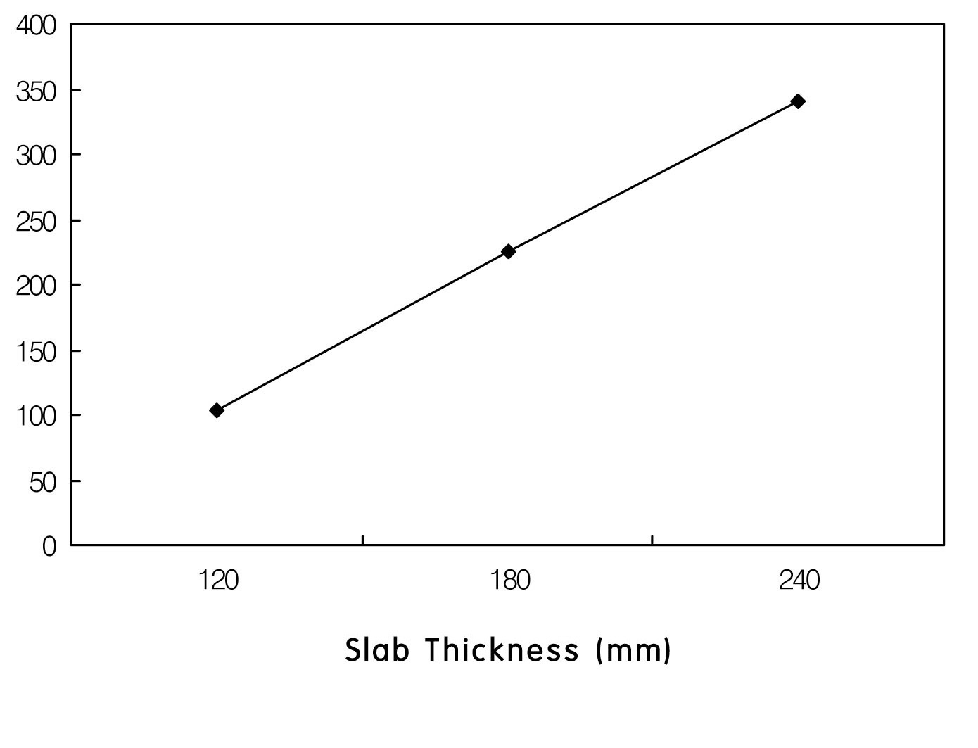
Fig. 10(b) presents the maximum reaction forces for all cases. The reaction force of HMS is about double that of the other steels. This result can be compared with the results of the colliding test in Kojima [3], where RC slabs with various thicknesses were collided with impacting objects at 200 m/s. The maximum reaction versus slab thickness of Kojima [3] is shown in Fig. 11, where the reaction forces are proportional to the slab thickness. Therefore, the overall resistance of the model with the HMS plate is superior to those of the other models, considering reaction forces and the constant thicknesses of the steel plates. The comparison among the 9 models with various steel plates showed relatively little local damage of the HMS plate target with the other conditions fixed.
[Table 5.] Velocity of the Impacting Object at the Instance of Collision

Velocity of the Impacting Object at the Instance of Collision
4.2 Evaluation of Local Damages under Various Impacting Angles
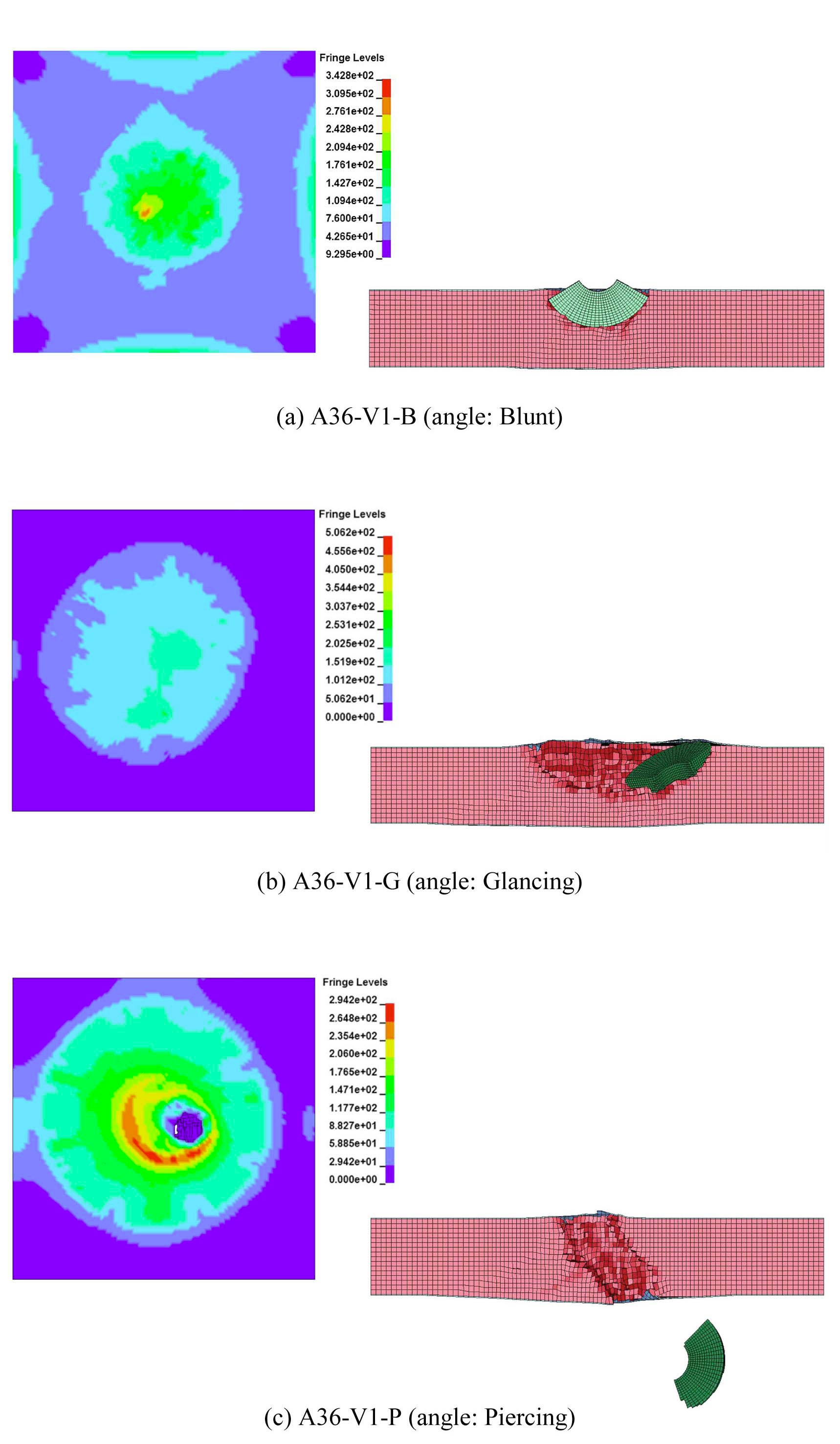
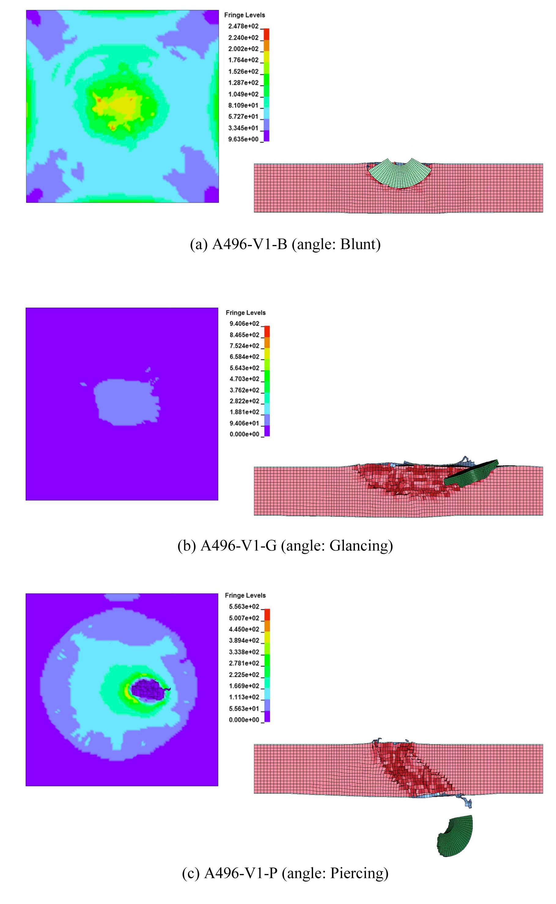
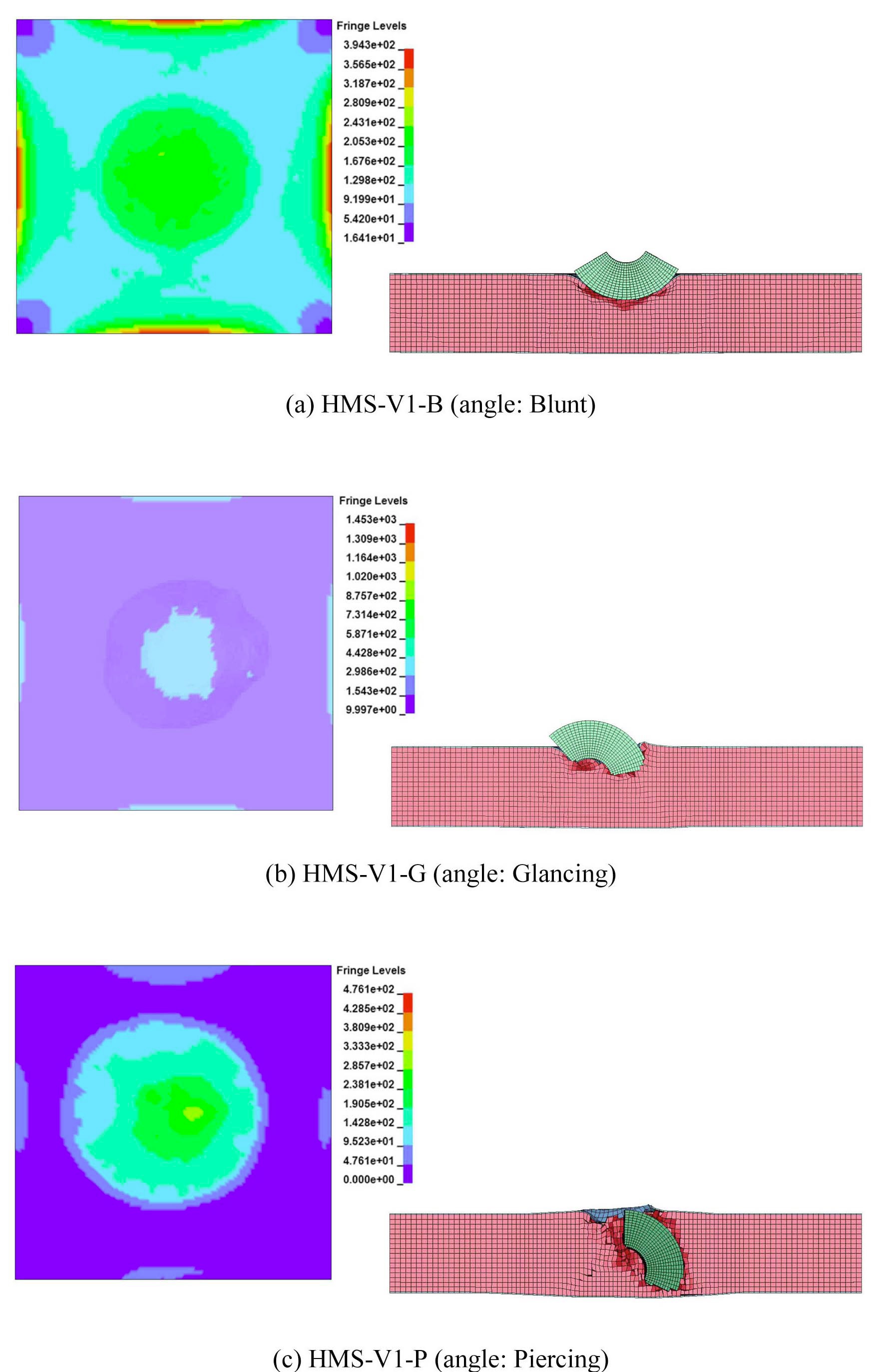
To evaluate the local damage of the SC structure according to the impacting angle, 9 models in Table 6 were selected from the 15 models in Table 2 and analyzed. The shape of the damage on the back panel and cross section are presented in Fig. 12 ~ Fig. 14. The maximum depths of penetration and reaction forces are compared in Fig. 15.
For A36 and A496 type steel models, the blunt angle and glancing angle cases show partial penetration, whereas the piercing angle cases show full penetration. For the HMS model, all cases experienced partial penetration.
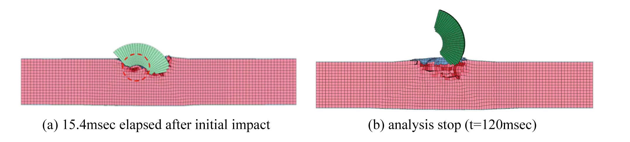
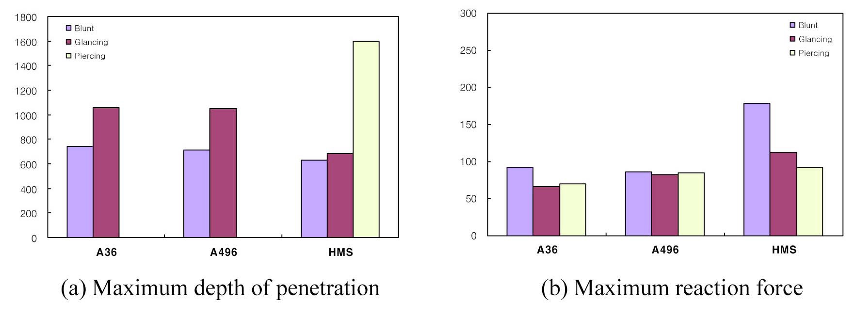
Fig. 15(a) presents the maximum depth of penetration according to the impacting angle, where resulting depths varied. The glancing angle case resulted in partial penetration that was 1.44 times deeper than that of the blunt angle
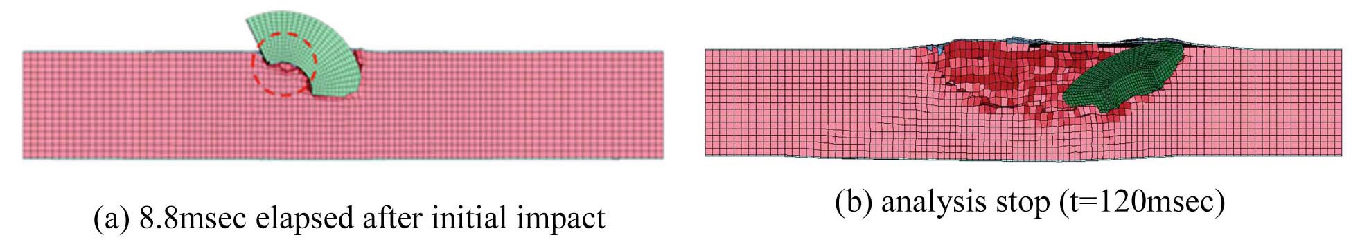
case for A36 steel. Similarly, the glancing angle case resulted in partial penetration that was 1.48 times deeper than that of the blunt angle case for A496 steel. For HMS, the glancing angle penetration was 1.08 times deeper than the blunt angle penetration and the piercing angle penetration was 2.58 times deeper than the blunt angle penetration. The little difference between the glancing angle and the blunt angle of HMS can be explained by Fig. 16 and Fig. 17. For the glancing impact on A36 and A486 steel plates, the circled part of the impacting object (Fig. 16 & 17) caused significant damage to the surface steel plate and it moved as described in Fig. 16 (b). For the glancing impact on the HMS plate, the plate resisted the impact and prevented further penetration. The difference in their damages seems to be due to the difference in the contacting areas for different impacting angles. The dynamic energy of the
impacting object is consistent (
4.3 Evaluation of Local Damages under Various Impacting Velocities
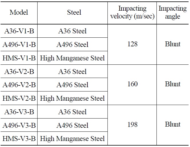
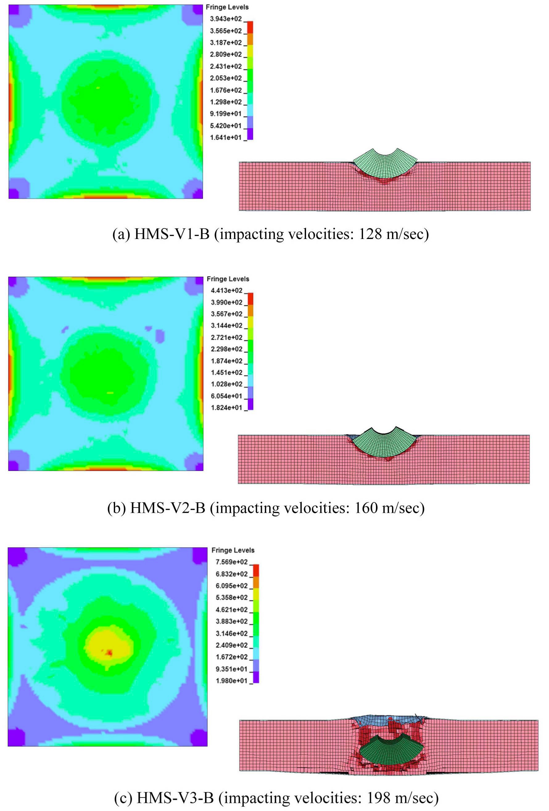
To evaluate the effect of impacting velocity on local damage under the condition of same material and same angle, 9 models in Table 7 were selected. The shapes of damages on the back face and cross section are shown in Fig. 18 ~ Fig. 20. Fig. 21 compares the maximum depths of penetration and the maximum reaction forces for various impacting velocities.
Local damage analyses for three impacting velocities (128 m/sec, 160 m/sec, 198 m/sec) revealed that a higher impacting velocity caused more severe damage to the target structure. In particular, the 198 m/sec speed case of the A36 and A496 models showed full penetration. In Fig 21(a), the
[Table 6.] Model specification for impacting angle analysis
Model specification for impacting angle analysis
depths of penetration of the A36 and A496 models increased by about 1.6 times when the speed increased from 128 m/sec to 160 m/sec, whereas the depth of penetration
[Table 7.] Model Specification for Impacting Velocity Analysis

Model Specification for Impacting Velocity Analysis
of the HMS model increased by about 1.12 and 2.61 times when the speed increased from 128 m/sec to 160 m/sec and 198 m/sec, respectively. Fig. 21(b) compares the maximum reaction forces and shows that the maximum reaction force increases with the impacting velocity. These results verify that the dynamic energy of the impacting object is transferred to the target structure as an impulse that causes local damage.
This study evaluated local damages of the SC wall of a reactor structure by a turbine impacting object. The SC structure was modeled with A36, A496 structural steels and
HMS, which has superior ductility and energy absorbing capability. Impacting analysis revealed the effects of impacting velocity, impacting angle, and material characteristics of the target. The important results are as follows:
The maximum penetration depth is largest in the Piercing case, medium in the Glancing case, and smallest in
the Blunt case, which can be explained by the fact that a small impacting area causes high stress when all other conditions are equal. The A36 and A496 SC plates experienced full penetration in the case of Piercing angle impact, whereas the HMS SC plate was partially penetrated in all cases.
Analysis of the impacting velocity parameter showed that the degree of damage varied among materials and that the differences were significant in high velocity cases. For the impacting velocities of 128m/sec and 160m/sec, all plates experienced partial penetration, but the HMS plate showed significantly less damage. For the case of 198m/sec impacting velocity, the A36 and A496 SC plates were fully penetrated, whereas the HMS plate was partially penetrated. As expected, HMS with high ductility absorbed the impacting energy, preventing full penetration.
Based on these results, it is concluded that studies on the future use of HMS for structures with high safety requirements needs to be continued.