Extensive number of cracks have been detected in the SG tubes of Ulchin Unit Three and Four NPPs (U3 and U4). Most of those cracks were axially-oriented ODSCC at the contact positions between tubes and egg-crate TSPs. The cracks are detected by Bobbin coil, and then confirmed and sized by MRPC inspection. All tubes with confirmed cracks must be repaired by plug or sleeve, upon the repairon- detection criterion. The cracks at the TSP location were detected first during the 8th ISI. The number of cracks has increased steeply afterwards. SGs of both units were chemically cleaned during the 10th refueling outage. The number of cracks detected by the inspection subsequent to the chemical cleaning increased explosively. There were more cracks in U4 than in U3. The number of tubes requiring repair in U4 SGs far exceeded the licensed plug limit of the plant, 18% of total tubes each SG, so that the operation of an 11th cycle was given up. U3 could go to the 11th cycle of operation after repairing hundreds of tubes. The operation periods for U3 and U4 were 11.7/11.5EFPYs at the 10th ISI.
U3, U4 and four other units, Youngwang Units Three to Six (Y3~6), are identical Korean units. They are CEdesigned 1,000MWe reactors with two loops, and their SG tubes are Alloy 600HTMA supplied per CE purchase specification. 3/4” tubes are supported by egg-crate TSPs.
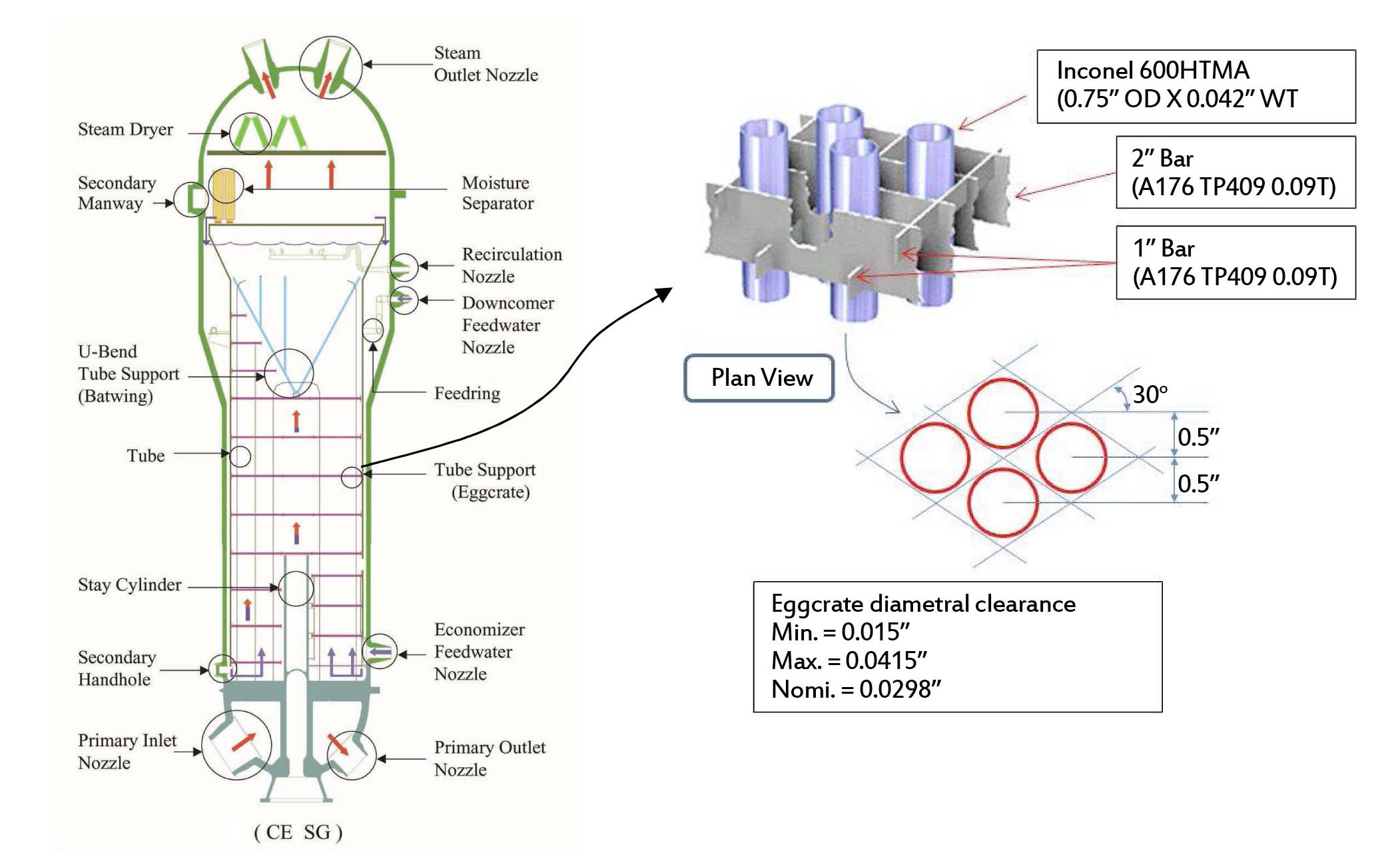
Structures of SG and TSP are seen in figure 1. The cracks at TSP had not been detected in Y3~6, until 67 cracks were detected in Y4 during the 13th ISI recently.
This paper is to describe the results of a root cause evaluation of the ODSCC in the SG tubes of U4. General understanding of the cracking mechanism is described, and then the different susceptibility to ODSCC among the identical units is discussed based on material and residual stress of the SG tubes.
2. GENERAL UNDERSTANDING OF THE CRACKING MECHANISM
SCC of SG tubes has been the subject of extensive researches [1~6]. It is well understood that SCC develops under the concurrent combination of three indispensible elements; susceptible material, causative environment, and tensile stress. The SCC depends on a specific combination of material and environment. It is known that Alloy 600 is susceptible to SCC under the primary water and secondary water environment of PWRs. Alloy 600MA tubes are more susceptible to SCC than Alloy 600TT and Alloy 690TT. Alloy 600HTMA is a version of Alloy 600MA, where the tube purchase specification required the final mill anneal temperature controlled high above 1040℃. Chromium carbides are fully resolved into solution, and the grain grows bigger during mill anneal at this high temperature. During cool down from the mill anneal, chromium carbides are precipitated preferentially at the grain boundary. Alloy 600HTMA is known to be less susceptible to SCC than Alloy 600LTMA, but still more susceptible than Alloy 600TT and Alloy 690TT. It is plausible that the susceptibility of Alloy 600HTMA tubes is the major cause of the extensive cracking.
SCC is a thermally activated reaction, so that the rate of cracking depends on temperature as given by the Arrhenius equation;
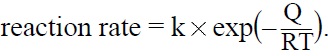
Where k is a rate constant, R is gas constant (8.31Joule/mol), T is absolute temperature in °K, and Q is the activation energy. The activation energy of ODSCC is known as approximately 200kJ/mol [3]. The large activation energy makes the rate of SCC increase very rapidly with increasing temperature. The high hot leg temperature, 327℃ (621℉) as designed, is an obvious cause of the accelerated ODSCC. U4 SG maintained hot leg temperature of 324~325° throughout its whole life.
ODSCC of SG tubes have been very widespread among PWRs worldwide. The general mechanism of ODSCC is well understood [1~5]. Formation of localized impurityconcentrated solution inside occluded region is the prerequisite condition of ODSCC. An occluded zone with limited access of water forms at the contact between tube surface and support structure and/or sludge deposit. Localized boiling inside the occluded zone leads to a concentration of less volatile impurities. The concentration factor may be as high as 108, depending on the geometry of the crevice and amount of superheat. This phenomenon is called a “hide-out” of impurities because of the superheating of the primary coolant. The hide-out returns as the power output is reduced to zero, because the superheat is removed.
Details of the following items listed below were reviewed carefully in order to find the root cause of the distinct susceptibility of U4 SG tubes to ODSCC.
- SG tubing materials; tube purchase specifications, manufacturing process, chemistry, microstructure, and mechanical properties
- Tube manufacturing residual stress
- SG design and manufacturing: tube purchase and QA documents, manufacturing records, design changes
- Operation temperature: hot leg operation temperature
- Water chemistry: operation water chemistry, chemistry malfunctions, hide out-return test
- Sludge deposit; amount of sludge deposit
The design features of U3&4 and Y3~6 SGs remained identical without any changes which might affect the susceptibility of SG tubes to ODSCC. Manufacturing records were reviewed, and any possibility of deteriorating performance of SG tubes was not noted. The chemistry was well maintained throughout the operation period, with the level of impurities far below the limit of industry guidelines [1]. There were no chemical elements creating a possibility of making U4 SGs more susceptible to ODSCC. All units had heavy sludge deposit in the tube to the TSP contact position. The plant data were not good enough to compare the extent of sludge deposition among the units with quantitative rigorousness.
It is noted that the hot leg temperature which was reduced as ORT was implemented from the 8th cycle of Y3 and the 7th cycle of Y4. The extent of hot leg temperature reduction was not substantial, only approximately 3℃. It is calculated by the Arrhenius equation with the activation energy of 200kJ/mol that the time required until failure by ODSCC is lengthened by 18% if hot leg temperature is reduced by 3℃. It is obvious that ORT solely cannot explain the different susceptibility between U3&4 and Y3&4 SGs.
It was found during the plant data survey that fifteen tubes purchased originally for Y3&4 were added to U4 SGs. It is believed that some of spare tubes were left unused after construction of Y3&4 SGs and they were added to the spare tubes for U4 SGs. No cracks have been detected in those tubes yet, even as twelve of the fifteen tubes are located in the densely crack populated zone, where ODSCC were detected in approximately 30% of the neighboring tubes. It is statistically valid, above 98% confidence, to say that the tubes in Y3&4 are less susceptible to ODSCC than tubes in U4.
It seems obvious from the above discussion that the root cause evaluation needs to focus on the material and residual stress of SG tubes.
3.2 Sludge Deposition, Thermal Hydraulics, and Chemical Cleaning
Most cracks in U4 SGs were detected at the position of line contact between the tubes and egg crate strips. The egg crates are composed of one inch and two inch wide strips, so that line contacts are formed between tubes and strips. It is understood that sludge deposits earlier, prefeentially near line contacts as compared to the rest of tube surface, and that occluded region is formed efficiently by sludge deposition near the line contacts. The distribution of sludge deposit inside the secondary side of SGs depends on thermal hydraulics. It is known that more sludge deposits in the region of high steam quality and fast flow of fluid. The thermal hydraulics of a SG depends on its design specifics. The thermal hydraulics of U4 SGs was analyzed using industry software, ATHOS/SGAP [7]. The analysis indicated that the sludge depositing tendency is homogeneously distributed in a wide range, throughout the mid height TSPs in the hot leg side. The cracks in U4 SGs distributed densely in the range between the 4th and the 9th TSPs, near the center region of the hemisphere plane. This densely cracked region coincided well with the preferential sludge deposition region as defined by the thermalhydraulics analysis. In some other units abroad with common design features with U4, a narrow region was defined with highly preferential sludge deposition. In those units, the cracks started to be detected earlier in life in the narrow highly preferential sludge deposition region. It is understood from the thermal hydraulic of U4 SGs why the number of cracks detected each outage increased steeply after the cracks were detected first during the 8th outage. Numerous tiny cracks developed homogeneously throughout the wide range of SGs, and only a few of them started to be detected in the 8th outage. More cracks are detected in the next outage, and even more in the next. The chemical cleanings implemented during the 10th outage removed 3,632 and 3,786 kg of sludge from SGs of U3 and U4. The post cleaning MRPC inspection confirmed that the sludge deposit at the tube-TSP contact location was removed effectively. It is known that the crack detection capability of Bobbin coil inspection is enhanced distinctly by chemical cleaning. There are correlations between the amplitude of the Bobbin coil signal and the depth of crack, as measured by analyzing MRPC signals. When the linear correlations are compared between the 9th ISI and 10th ISI, it was found that the amplitude of Bobbin coil signal increased substantially after the chemical cleaning. The increased signal voltage amplitude explains why crack detection capability is enhanced distinctly by the chemical cleaning. It seems plausible that the explosively increased number of cracks detected by the 10th ISI of U4 SGs owes, partly at least, to the enhanced detection capability by the chemical cleaning.
It is not confirmed as to the specific chemistry inside the occluded region which caused the ODSCC in U3 and U4 SGs, even though theories on hideout and hideout return are well developed. It is very difficult to examine the specific hideout chemistry of operating SGs, and Alloy 600MA tubes which are susceptible to SCC under a wide spectrum of chemistry, from acid to alkaline. Model boiler is a useful experimental method to simulate ODSCC of SG tubes under heat transferring hideout condition, but it is very time consuming and still there remains uncertainties. Jacques Daret suggested, based on his 25 years of model boiler experiments, that the following chemistries may have caused ODSCC as detected widely in the operating SGs [5].
- Weak acidic sulfate contamination caused by decomposition of ion exchange resins
- Weak basic environment
- Lead (or its oxide) contamination under neutral environment
A few tubes were pulled out from U4 SGs in order to confirm the existence of crack and their size and shape an measured by ISI, and to investigate the chemistry near the cracks. The chemistry of oxide film on the surface of tube near crack mouth was analyzed using TEM/EDS. The chromium-rich inner oxide was confirmed by the TEM/EDS analysis, indicating that the surface was not exposed to strongly alkaline solution. Surface of the crack flank of each crack was analyzed using SEM/EDS, without verifying any contaminants like lead or sulfur. The hideout return chemistry database in the plant indicated that the crevice maintained an alkaline rather than acidic chemistry. It is speculated from the above findings that the ODSCC of U4 SGs developed under a mildly alkaline environment.
3.4 Tubing Material and Manufacturing Process
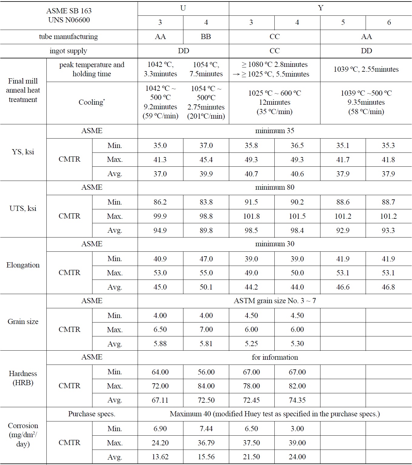
The tubing materials of the six Korean units are summarized in table 1. The chemistry of those tubes is tabulated as table 2. It is noted that all material properties and chemistry are within the acceptable range given by ASME PV&B Code Section II SB-163 and tube purchase specification. The six units are divided into three groups depending on tube manufacturers and ingot suppliers; U3, 5, 6, and U4, and Y3&4. Two points are noted among the table 1 and 2, as below.
- Cooling rate from the final mill anneal peak temperature is substantially slower for Y3&4, and faster for U4. The cooling rates for U3 and Y5&6 are in between.
- The chromium contents of tubes in Y3&4 are substantially higher than the others.
The mill anneal process depends on the tube manufacturers. The final mill anneal is the critical step influencing the final microstructure of tubing material. The heavily cold worked structure is re-crystallized and grains grow bigger by mill anneal. Chromium carbides are dissolved during mill anneals at high temperature, and precipitate along grain boundary during cooling from mill anneal. Coarse carbides are precipitated by slow cooling and fine carbides by fast cooling. The precipitation of chromium carbide accompanies chromium depletion in the matrix adjacent to the carbide. Chromium depletion along grain boundary is called sensitization.
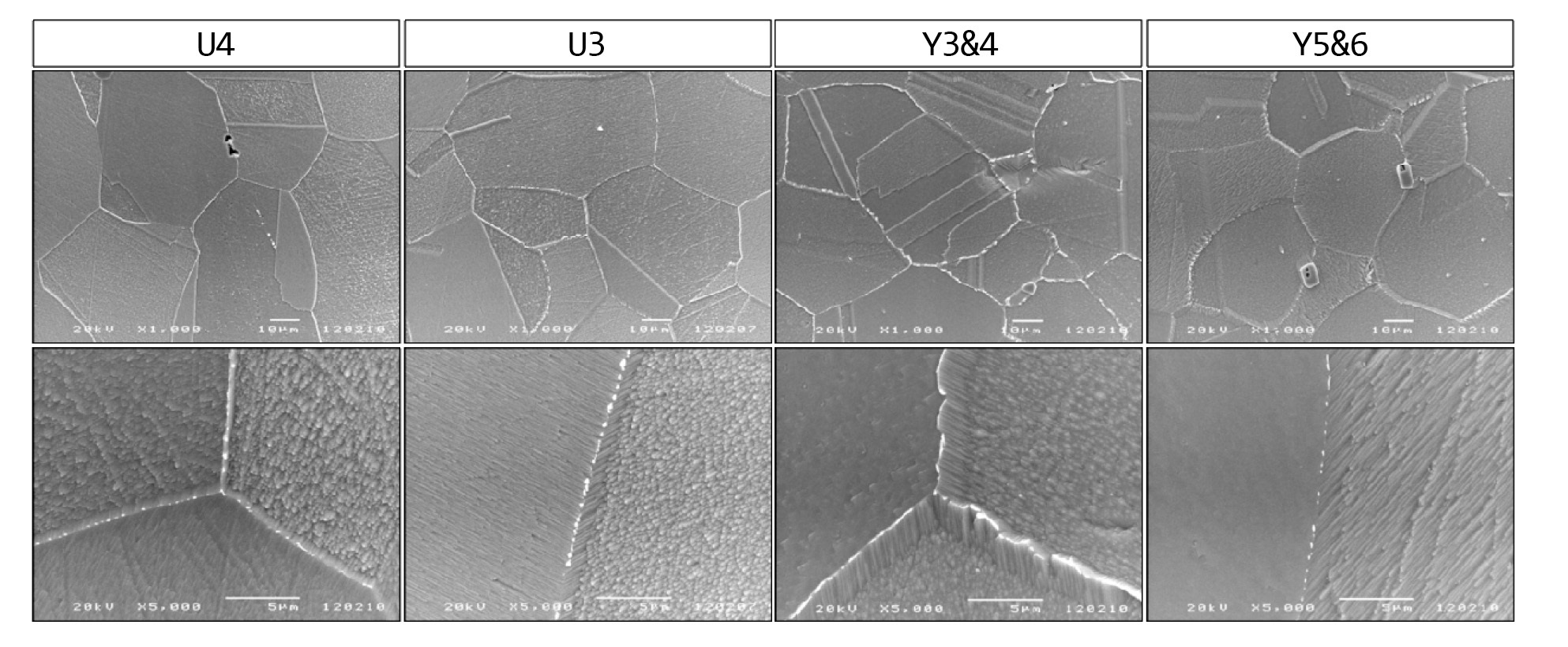
Figure 2 shows carbide distributions along grain boundary of U3, U4, Y3&4, and Y5&6 tubes as taken by SEM. The specimens were etched in 2% bromine and 98% methanol solution before SEM observation. Intra-granular carbides are not seen in any tube, as all tubes were mill annealed at high temperature above 1040℃. Fine carbides are populated densely along grain boundary in U3, U4, and Y5&6 tubes, while coarse and longish carbides are distributed continuously along the grain boundary in Y3&4 tubes. Some of the carbides are somewhat longish in U3 and Y5&6 tubes, while any longish carbide is not seen in U4 tubes. It is noted that the micro structural features are divided into three groups, similar to the combined tube manufacturer and ingot suppliers. It is understood that the carbide morphology depends on the cooling rate after mill anneal. The grain boundaries are serrated shape mostly in Y3&4, while no serrated grain boundary is seen in U4 tubes, and a small portion of serrated boundaries are noted in U3 and Y5&6 tubes. The tubes in U3 and Y5&6 may be considered the same, since they were made by the same manufacturer with identical purchase specification.
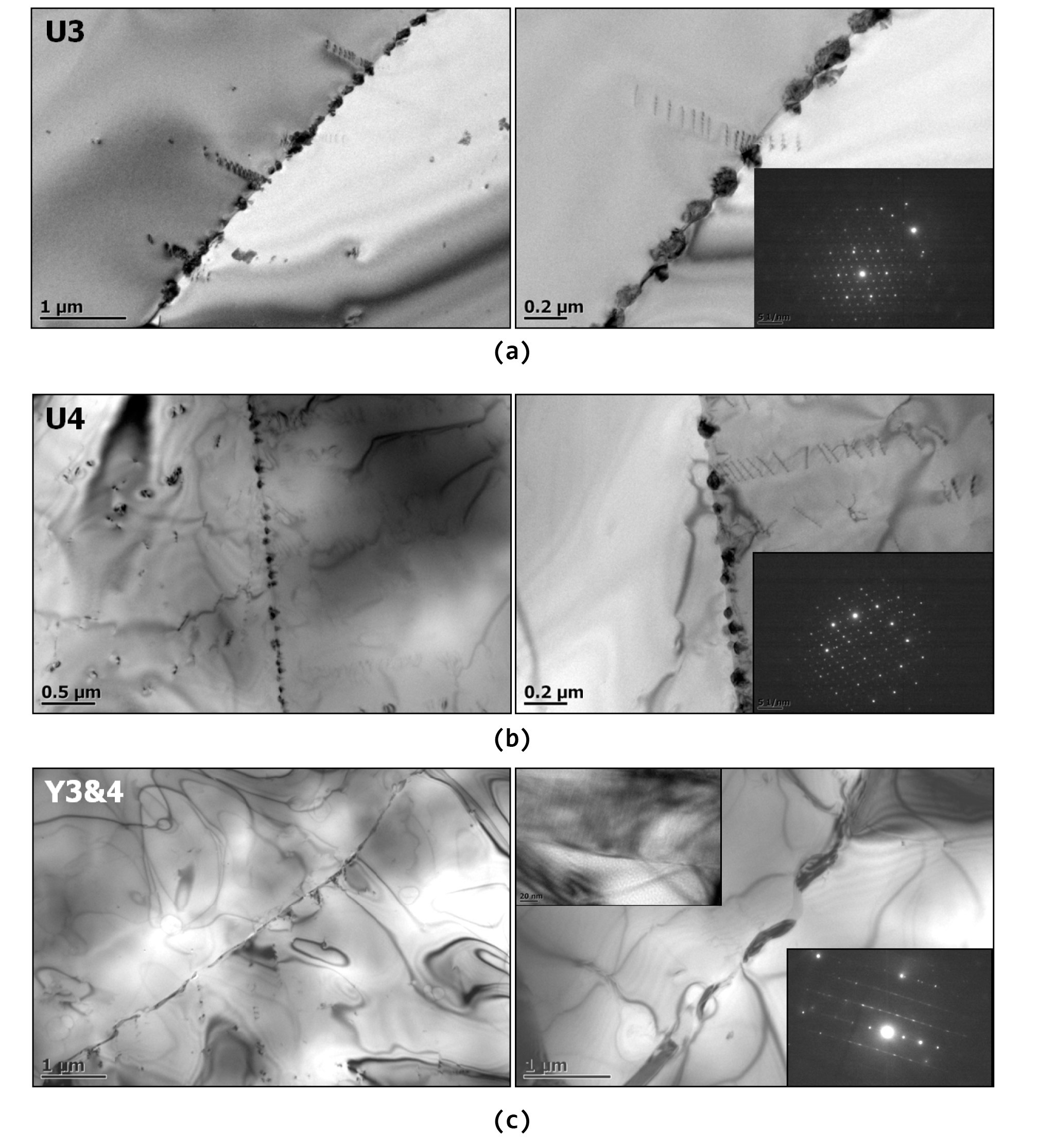
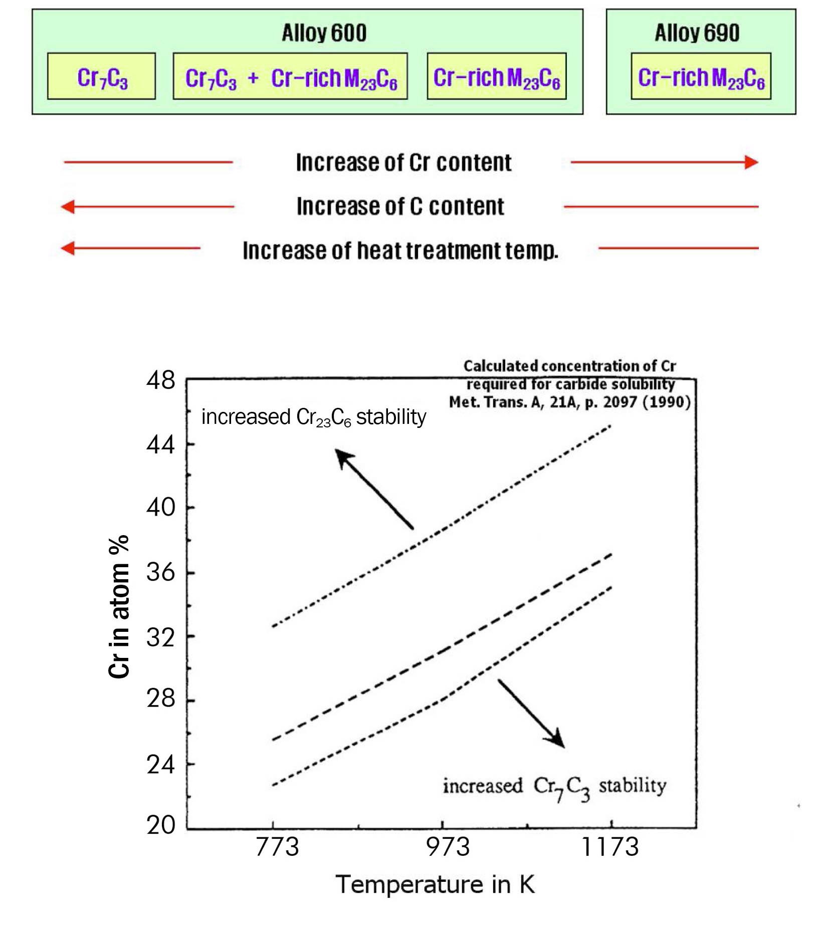
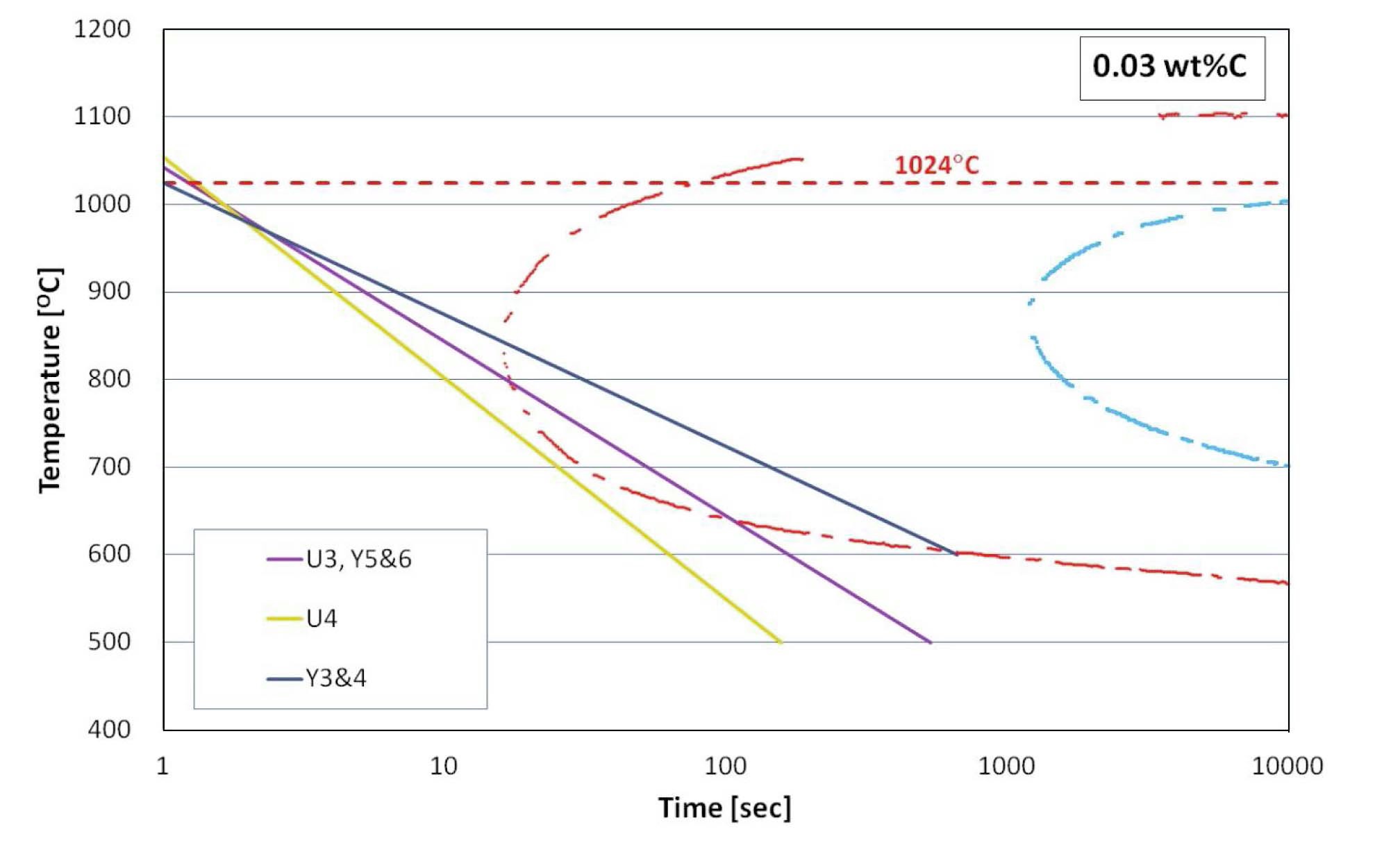
TEM images are seen in figure 3 for U3, U4, and Y3&4. Coarse and longish carbides are confirmed for Y3&4, while fine carbides for U4. Electron diffraction patterns indicated that the carbides were Cr7C3 in Y3&4, and Cr-rich M23C6 in the others [8,9]. It is known that both Cr7C3 and Cr-rich M23C6 are precipitated in nickel alloys, depending on alloy composition and temperature [10]. Figure 4 shows the preference of each phase depending on alloy composition and temperature. M23C6 is precipitated at lower temperature, and Cr7C3 at higher temperature. Schematic cooling curves are given in figure 5 along with the TTT diagram. It is understood that the slow cooling led to the precipitation of coarse Cr7C3 carbides at higher temperature in Y3&4 tubes, while fast cooling led to precipitation of fine M23C6 carbides at lower temperature.
The extent of chromium depletion in the grain boundary was analyzed using EDS/ATEM. The extent of peak chromium depletion in U3/U4/Y3&4 tubes were measured as 3.0~5.1/3.1~3.4/6.9~7.95%. It is noted that the extent of sensitization is bigger in Y3&4 because of slow cooling. It is noted also that chromium content in Y3&4 tubes are distinctly higher than the others, 16.62~16.74% approaching
[Table 1.] SG Tubes of Six Units

SG Tubes of Six Units
close to the upper limit of 17% in the allowable range, while the other tubes are close to the middle of the range, 15.5%. It is understood that the higher chromium content is targeted intentionally by the manufacturer in order to deal with the heavier sensitization during slow cooling after mill anneal of Y3&4 tubes.
[Table 2.] Chemistry of SG Tubes in Six Units
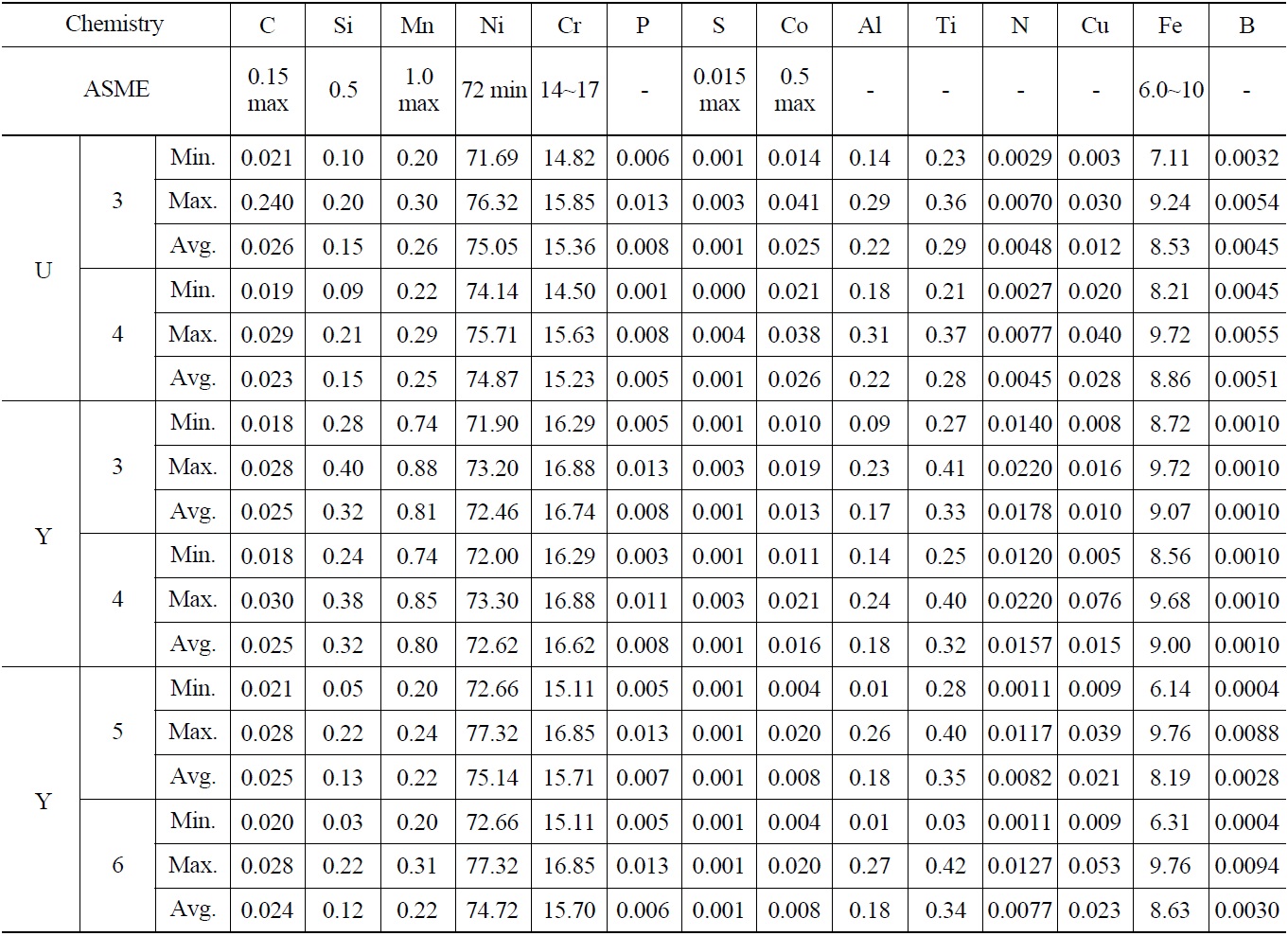
Chemistry of SG Tubes in Six Units
3.5 Manufacturing Residual Stress
During the manufacturing process, tubes are deformed after final mill anneal leaving residual stress. It is known that the straightening process and OD polishing are two major steps responsible for the final residual stress [11]. The residual stress of Alloy 600MA tubes can be very high depending on the manufacturing process, while residual stress of Alloy 600TT and 690TT tubes is controlled low
since the stress is relieved by TT heat treatment. It was found that there were not any requirements limiting the extent of residual stress in the purchase specification of the Alloy 600HTMA tubes. While the current specification of Alloy 690TT SG tubes requires the manufacturing residual stress controlled very low, below 34MPa.
The straightening is a roll process to straighten the long range curvature of mill annealed tubes. Spiral grooves are made along the length of tubes since tubes are deformed
locally at the contact with the rollers. The outside surface of tubes should be ground down. A minimum of 0.01mm is removed from the wall thickness by the grinding. It is known that the state of residual stress of the final tube depends on specific details of the straightening process and OD grinding. The profile of the spiral groove in ID and OD surface was measured using a HOMMEL-ETAMIC T8000 profiler. The period of the spiral groove pattern was measured approximately 40mm, coinciding with typical pattern of straightening roll grooves. The maximum amplitudes of the surface profile, height between peak to valley, for U3, Y3&4, and Y5&6 tubes were 8.8/10.5/26.6
The amplitude of the surface profile was highest in Y5&6 tubes, but the residual stress was the smallest. It is understood that the residual stress does not correlate well with the amplitude of surface profile since the residual stress may depend on the long range curvature of the tubes before the straightening process and on the details of the OD surface grinding process. The reason why Y5&6 tubes showed substantially lower residual stress was not investigated since manufacturing details were not available. It is speculated that somewhat different OD grinding process affected the final residual stress state of Y5&6 tubes.
It is well known that stress corrosion cracking occurs only when susceptible material is exposed to a causative environment under tensile stress condition. The concurrent combination of the three key factors is the prerequisite for any SCC. It is well known that Alloy 600MA tube is susceptible to ODSCC under the operating conditions of PWRs. It is apparent that the high residual stress of Alloy 600MA tubes played a key role in the development of ODSCC. The operation stress on the tube is caused by the pressure and temperature differential between the ID and OD of tubes. The pressure differential hoop stress is calculated as 75.8MPa. The total circumferential stress as summation of the pressure differential hoop stress and the thermal stress is calculated to be 96.0MPa. The sludge deposition affects the temperature profile through the depth of tubes, so that the thermal stress is affected by sludge deposition. Computer aided model calculations of the total operation stress under varying sludge deposition profiles indicated that sludge deposition does not change the operation stress on the tube substantially, and the maximum possible operation stress was 102.6MPa in the circumferential direction. There have been a few suggestions on the threshold stress for SCC of SG tube [3,5]. The threshold stress for PWSCC is 241MPa. The threshold stress for ODSCC of Alloy 600MA tube depends on specifics of corrosive environment. It was 159MPa or 185MPa under caustic environment, and 215MPa under sulfate contaminated neutral or weakly alkaline solution. The operation stress is far lower than the threshold stress for ODSCC, indicating that the manufacturing residual stress played a critical role in the development of ODSCC. The summation of the operation stress and residual stress is calculated as in the range of 215~353MPa depending on units. It is plausible that the higher the tensile stress, the faster the development of SCC. It has been suggested the failure time depends of the reciprocal of σ4 ~σ6 for PWSCC [3]. It is believed that a similar relation is valid for ODSCC. It is understood that the extent of the residual stress is one of key variables defining the susceptibility of Alloy 600MA tubes to ODSCC, depending on specific units. It is suggested that the development of ODSCC will be retarded substantially in Y5&6 tubes than U3 tubes, as deduced by the lower residual stress with identical microstructure. Compressive residual stress at the OD surface of Y5&6 tubes is noted in Table 3.
It is apparent that Y3&4 tubes are less susceptible to ODSCC than U3 and U4 tubes even as the residual stress is more tensile. It has been suggested by numerous researchers that Alloy 600MA tubes with its continuous distribution of coarse carbides along the grain boundary are less susceptible to SCC than ones with discontinuous distribution of fine carbides [3~5,14,15]. G.P. Airey[15] examined precipitation of chromium carbides along grain boundary of Alloy 600 depending on thermal treatment in the temperature range 593~870℃. He compared microstructures of 13 different thermal treatment conditions. And then, he
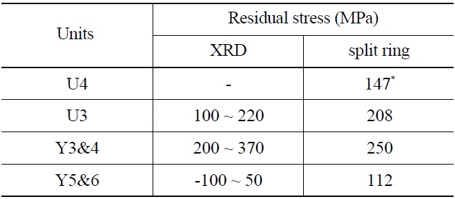
[Table 3.] Manufacturing Residual Stresses of SG Tubes in Six Units

Manufacturing Residual Stresses of SG Tubes in Six Units
verified that the maximum resistance to SCC correlated with the presence of semi continuous coarse carbides along the grain boundary. The microstructure of U4 tubes were comparable to tubes thermally treated during 1~10hours at 593℃, the size of the grain boundary carbides were 20~500 nm, while Y3&4 tubes were comparable to tubes thermally treated during 24hours at 705℃, the size of carbides in the range 500~2000 nm. It seems reasonable to argue that the micro-structural difference caused by different cooling rate from mill anneal is the dominating factor defining the susceptibility of SG tubes to ODSCC among U3, U4 and Y3&4 units.
The higher chromium content may also be a factor making Y3&4 tubes less susceptible to ODSCC. It is known that high chromium content makes nickel alloys less susceptible to SCC. Alloy 690, in particular, is a high chromium version of Alloy 600, and far less susceptible to SCC. The allowable chromium content is 15~17% for Alloy 600, while 28~31% for Alloy 690. Alloy 690 is known to be almost immune to PWSCC and ODSCC. It is not clear, however, as to if a small difference of chromium contents, still within the allowable range of Alloy 600 chemistry, made a substantial difference.
- The remarkably more extensive ODSCC in U4 SG is because the U4 tubes are more susceptible to ODSCC than the other units.
- It is believed that the origin of the different susceptibilities of SG tubes to ODSCC among the six identical units is the different distribution of carbides along grain boundaries. U4 tubes were fast cooled after final mill anneal so that fine carbides were distributed along grain boundaries. Y3&4 tubes were slow cooled so that coarse and longish carbides were distributed along grain boundaries. Y3&4 tubes are remarkably less susceptible to ODSCC despite the longer operation years and the higher residual stress.
- Combination of pulled tube examination and plant hideout return database indicated that ODSCC developed under mildly basic chemical environment.
- The high manufacturing residual stress of Alloy 600 MA tube played a key role in developing ODSCC of U3 and U4 SGs. The manufacturing residual stress measured by XRD on OD surface and by split tube method indicated that there are quite different levels of manufacturing residual stress among the six units, which are believed to depend on details of straightening and OD grinding processes.
- It is anticipated that ODSCC of Y5&6 SG tubes will be retarded substantially compared with U3, since Y5&6 tubes has an identical microstructure with U3, but has substantially lower manufacturing residual stress.
ASME American Society of Mechanical Engineers
ASTM American Society for Testing and Materials
ATEM Analytical Transmission Electron Microscopy
ATHOS Analysis of the Thermal Hydraulics of a Steam Generator
CE Combustion Engineering
EDS Energy Dispersive Spectroscopy
EFPY Effective Full Power Years
EPRI Electric Power Research Institute
HTMA High Temperature Mill Annealed
ISI In-Service Inspection
LTMA Low Temperature Mill Annealed
MA Mill Annealed
MRPC Motorized Rotating Pancake Coil
NPP Nuclear Power Plant
ODSCC Outside Diameter Stress Corrosion Cracking
ORT Operation at Reduced Temperature
PV&B Pressure Vessel & Boilers
PWR Pressurized Water Reactor
SCC Stress Corrosion Cracking
SEM Scanning Electron Microscopy
SG Steam Generator
SGAP Steam Generator Analysis Package
TEM Transmission Electron Microscopy
TSP Tube Support Plate
TT Thermally Treated
TTT curve Time-Temperature-Transformation curve
XRD X-Ray Diffraction