Safety [1] is an important property for nuclear power plants in order to obtain permission from government authorities for their operation and possible export of power plant construction technology. As the nuclear reactor protection system (RPS) makes decisions for emergent reactor shutdown, RPS software should be verified throughout the entire software development life cycle (SDLC). Recent commercial digital I&Cs (Instrumentation & Controls) use a safe-level PLC (Programmable Logic Controller) as a common hardware platform for RPS,
Vendors such as
This paper presents a technique for the development of an '
The paper is organized as follows: Section 2 gives an introduction to a typical development process for RPS software and several techniques for validating '
explains translation algorithms and rules from FBDs into a subset of ANSI C programs. In order to aid understanding, we explain the rules with an example, a basic shutdown logic; '
1 AREVA (http://www.areva.com)
2 invensys (http://iom.invensys.com)
3 PONU Tech (http://www.ponu-tech.co.kr) for PLC segment was split from POSCO ICT (http://www.poscoict.co.kr)
4 ISTec GmbH (http://www.istec.de)
2. THE RPS SOFTWARE DEVELOPMENT PROCESS
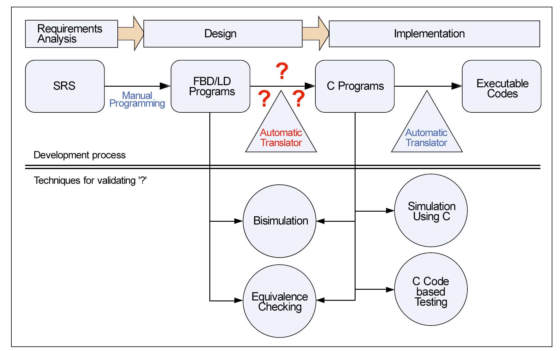
RPS (Reactor Protection System) is a real-time embedded system, implemented on the hardware - PLC (Programmable Logic Controller). The RPS software is designed in FBD/LD languages and then translated into C programs which will be compiled and loaded on PLCs. Fig.1 explains a typical software development process for RPSs as well as the techniques used for validating the '
The upper part describes a typical software development process as a waterfall model [16]. The SRS (Software Requirements Specification) is written in natural languages or formal specification languages [15,17,18]. Experts on PLC programming languages then translate the requirement specifications manually into design models programmed in FBD or LD. PLC vendors provide their own automatic translators from FBD/LD programs into ANSI C programs, while typically using COTS (Commercial Off-the-Shelf) software such as '
The lower part of the figure shows V&V (Verification and Validation) techniques which have been used to demonstrate the correctness and functional safety of the '
the FBD and C programs, since the FBDtoC translator can guarantee their behavioral consistency from the viewpoint of transformation theory.
An FBD (Function Block Diagram) consists of an arbitrary number of function blocks, '
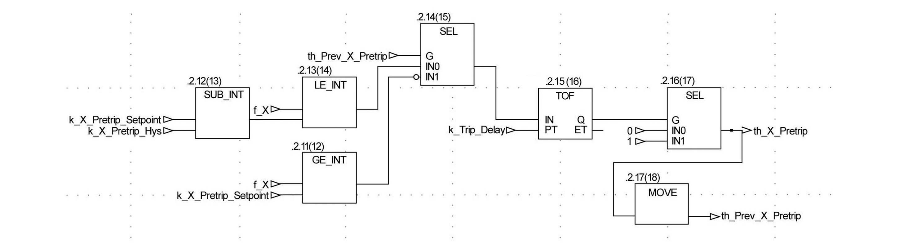
A part of preliminary FBD programs for the KNICS RPS BP (Bistable Processor) can be found in Fig.3. It was developed by domain experts from a formal requirements specification [13], and this paper uses the FBD as an example throughout the paper in order to remain consistent with our former research work and aid understanding. It creates a signal '
This subsection formally defines FBDs in accordance with the guide of denotational/operational semantics [25] of programming languages, of which more details can be found in [26]. We define the FBD programming language as a state transition system consisting of sub-components including basic blocks in a bottom-up manner, since an FBD is a network of function blocks sequentially executed.
A
Name : a name of function block
IP : a set of input ports
OP : a set of output ports, usually one
BD : behavioral description Σ(pFB, aFB), where
- pFB : a predicate on IP
- aFB : assignments on OP
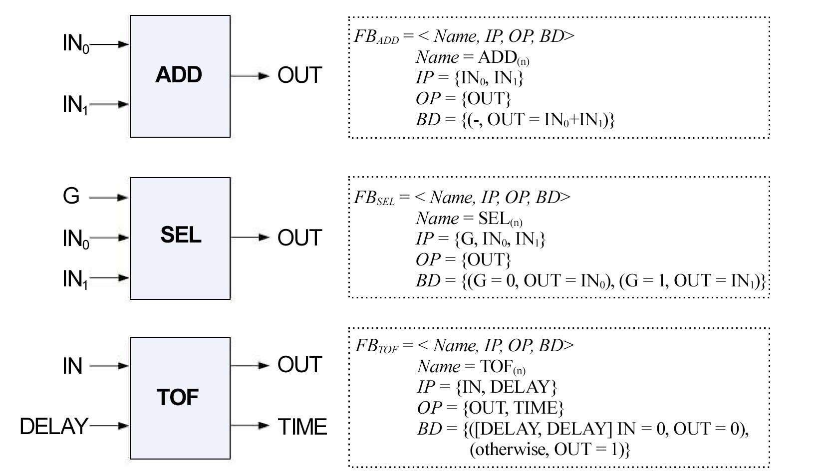
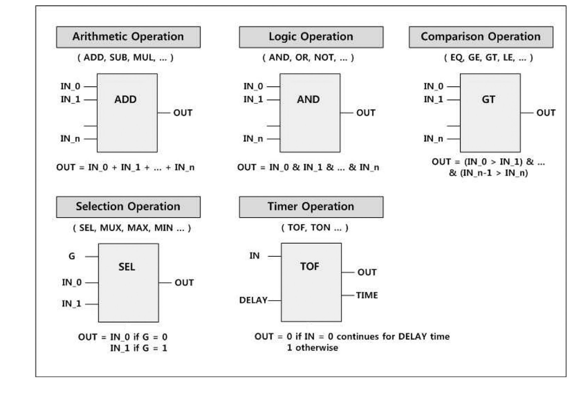
Fig.4 shows definitions of ADD, SEL and TOF function blocks. We do not restrict the form of predicates and assignments on ports in
A
Definition 2 (Component FBD)
FBs : a set of function blocks FBs
T :
- a set of transition (FBi.OPm, FBj.IPn) between function block FBi and FBj in FBs (provided that i ≠ j, and FBj.IPn means the n-th input port of function block FBj)
- ∀(FBi.OPm, FBj.IPn)∈ T, FBi has a sequential execution precedence on FBj
I : a set of input ports FB.IP, which do not appear in T and are assigned by VComp_FBD-I
O : a set of output ports FB.OP, which do not appear in T and are assigned by VComp_FBD-O
Behavior of a component FBD is defined as a function from a set of input variables to output variables of the component FBD. Variables in
A whole software programmed in FBD is structured with a number of component FBDs and their implicit interconnections. A
Definition 3 (System FBD)
- Component_FBDs : a set of component FBDs component_ FBDs
- T :
- a set of transitions (FBD1.Oi, FBD2.Ij) between Component FBDs FBD1 and FBD2 in FBDs (provided that FBD1.Oi is an i-th output port of FBD1 and FBD2.Ij is a j-th input port of FBD2)
- ∀(FBD1.Oi, FBD2.Ij)∈ T, FBD1 has a sequential execution precedence on FBD2
- I : a set of FBD's input ports FBD.I, which do not appear in T and are assigned by VSys_FBD-I
- O : a set of FBD's output ports FBD.O, which do not appear in T and re assigned by VSys_FBD-O
Similarly, a system FBD is defined as a function from a set of system input variables
We finally define the
Definition 4 (FBD Software System)
- S : a set of system states, σ [ VSys_FBD-O-Internal×VTimer ]
- VSys_FBD-O-Internal : a set of internal output variables in VSys_FBD-O
- VTimer : a set of timer function blocks
- S0 : an initial state in S
- R : a set of transition relation S×ISys_FBD → S'×OSys_FBD
- OSys_FBD = fSystem_FBD(ISys_FBD)
- d : a system scan cycle time
The variable
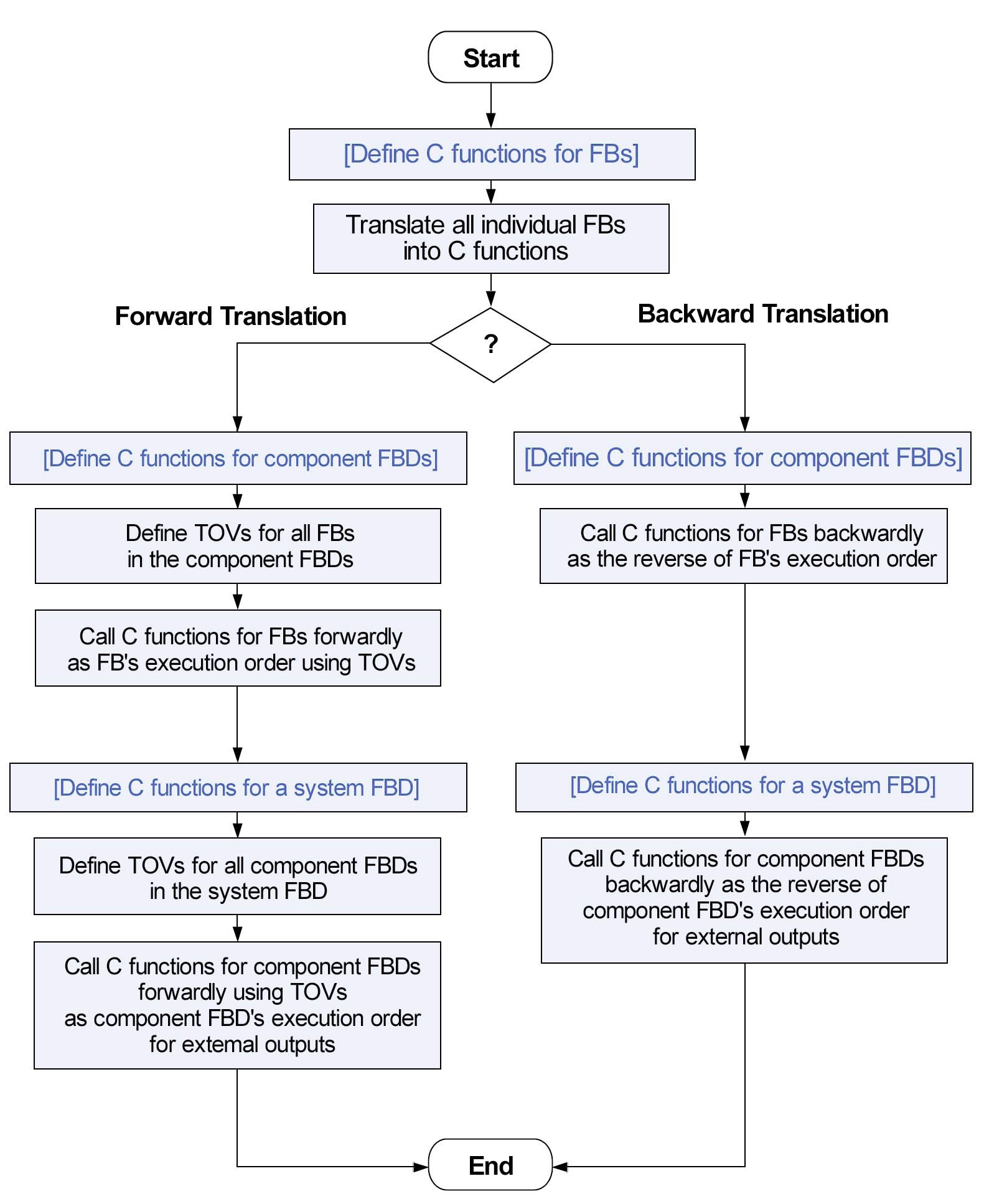
This paper proposes two ways to translate FBDs into C programs,
The one is the direction of calling C functions - forward or backward against the execution order of function blocks. The other is whether they use temporary output variables (TOVs) or not. We explain the backward translation first.
An FBD performs a data flow-based calculation according to a predefined execution order of function blocks consisting of the FBD. As the example of Fig.3, each function block has its own execution order. GE_INT numbered (12) is the function block first executed while MOVE numbered (18) is the last one. The backward translation algorithm basically works from the last function block executed to the one first executed. However, it may result in poor readability and understandability, since an FBD is composed of a number of function blocks interconnected sequentially, hierarchically and compositionally. It, however, produces more compact C programs than the forward translation.
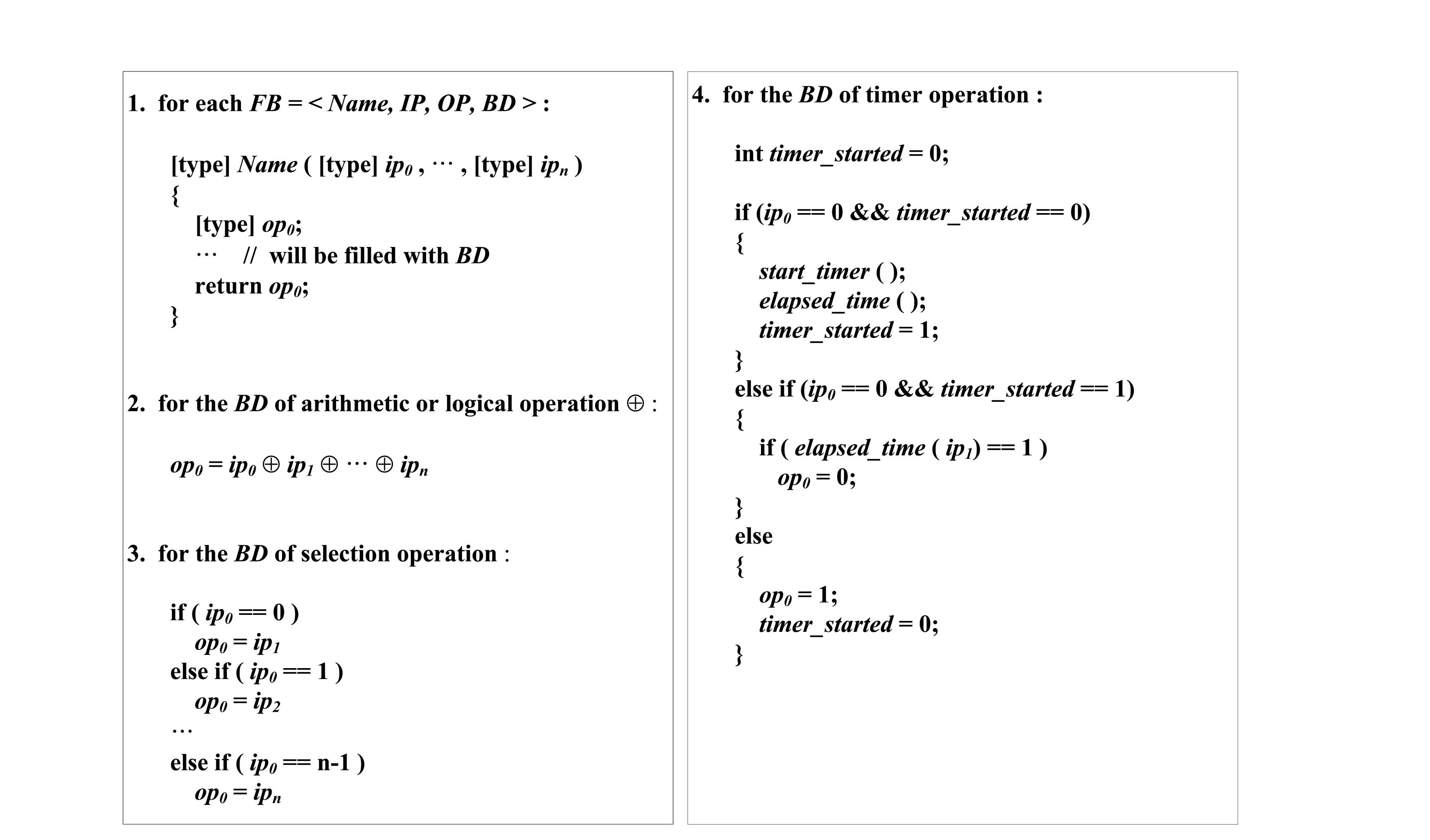
4.1.1 Translation of Function Blocks
The rules in Fig.6 define how to translate a function block into a corresponding C function. For each function block, a matching C function is defined and called in
The timer operation defined in Rule 4 has more complex controls than others. Since it generates 0 value of
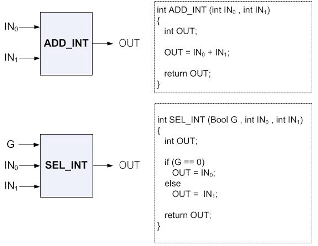
Fig.7 shows an example translating ADD and SEL function blocks. We added a type of output (such as INT for integer) to the function blocks. In practice, PLC software engineering tools provided by PLC vendors keep different function blocks for different output types,
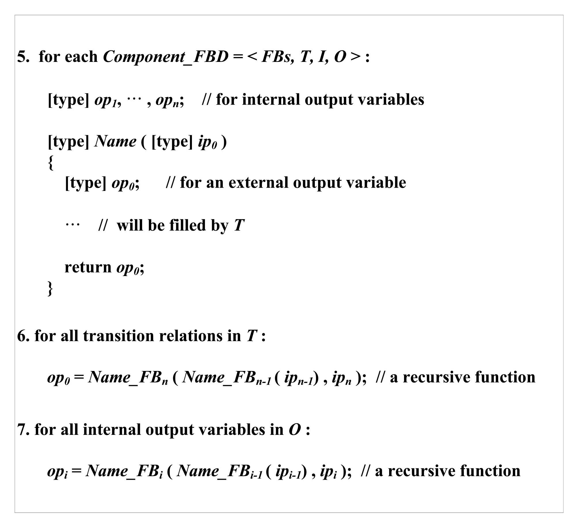
4.1.2 Translation of Component FBDs
Function blocks are composed into a component FBD according to their sequential execution orders. The FBD presented in Fig.3 is a simple case of component FBD, composed of 7 function blocks. A component FBD is translated into a C function, which calls C functions of basic function blocks sequentially according to their execution orders while passing inputs and outputs. The rules in Fig.8 define the translation of component FBDs.
A component FBD has one external output and several internal outputs, as defined in Section 3. Even if internal output variables look similar to external outputs, their usage and purpose are different from external outputs. They are commonly used to store information and to be used in later execution cycles. Rule 5 translates internal output variables into global variables which are defined out of the scope of
the component’s definition, since they are used and called across multiple executions.
The behavior of a component FBD is defined as the sequential backward calls of all function blocks as defined in
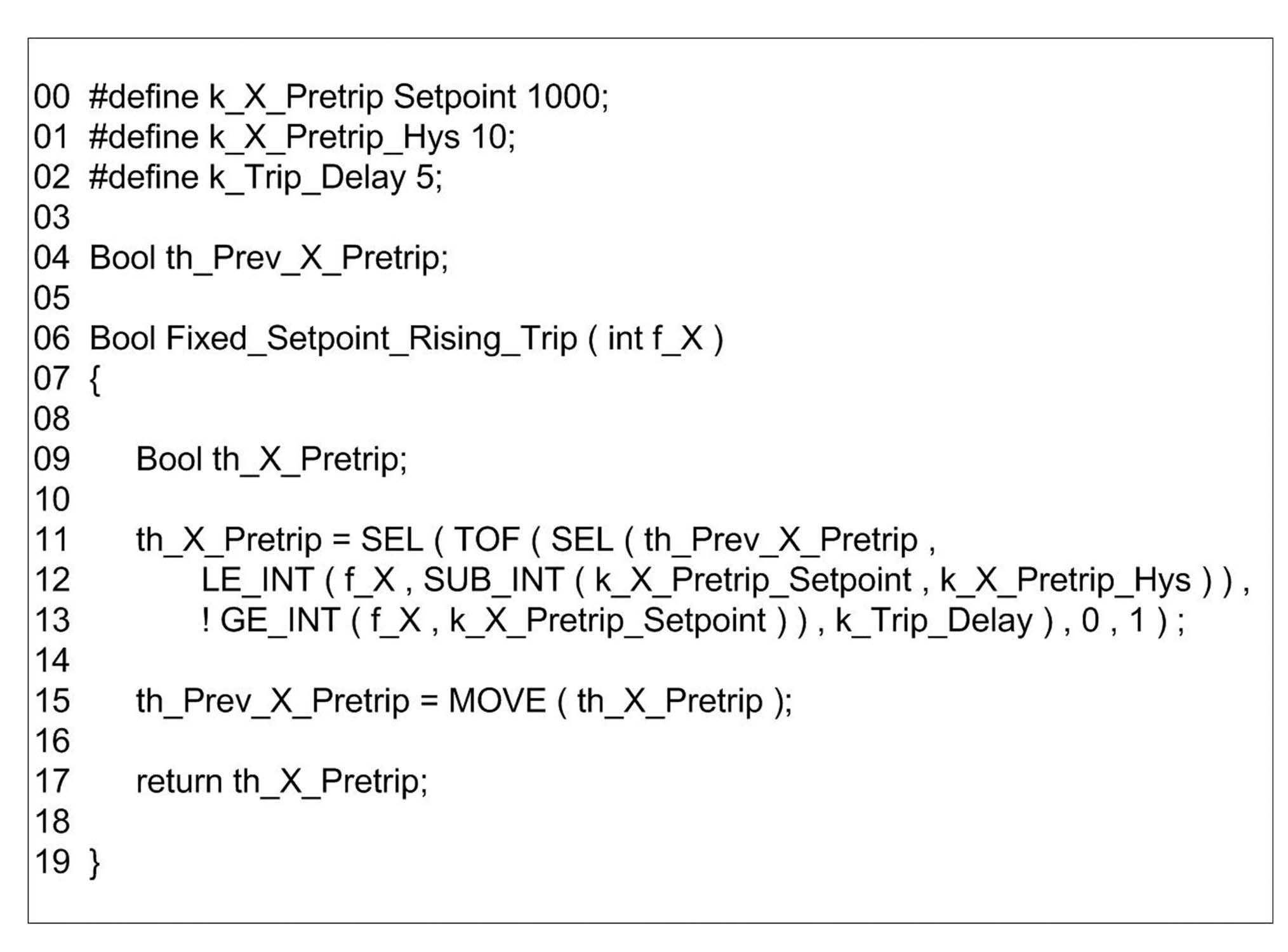
Fig.9 is a translation example for the component FBD depicted in Fig.3. We assumed that all basic function blocks consisting of the FBD were defined prior to it. For convenience, we also defined all constants with ‘#
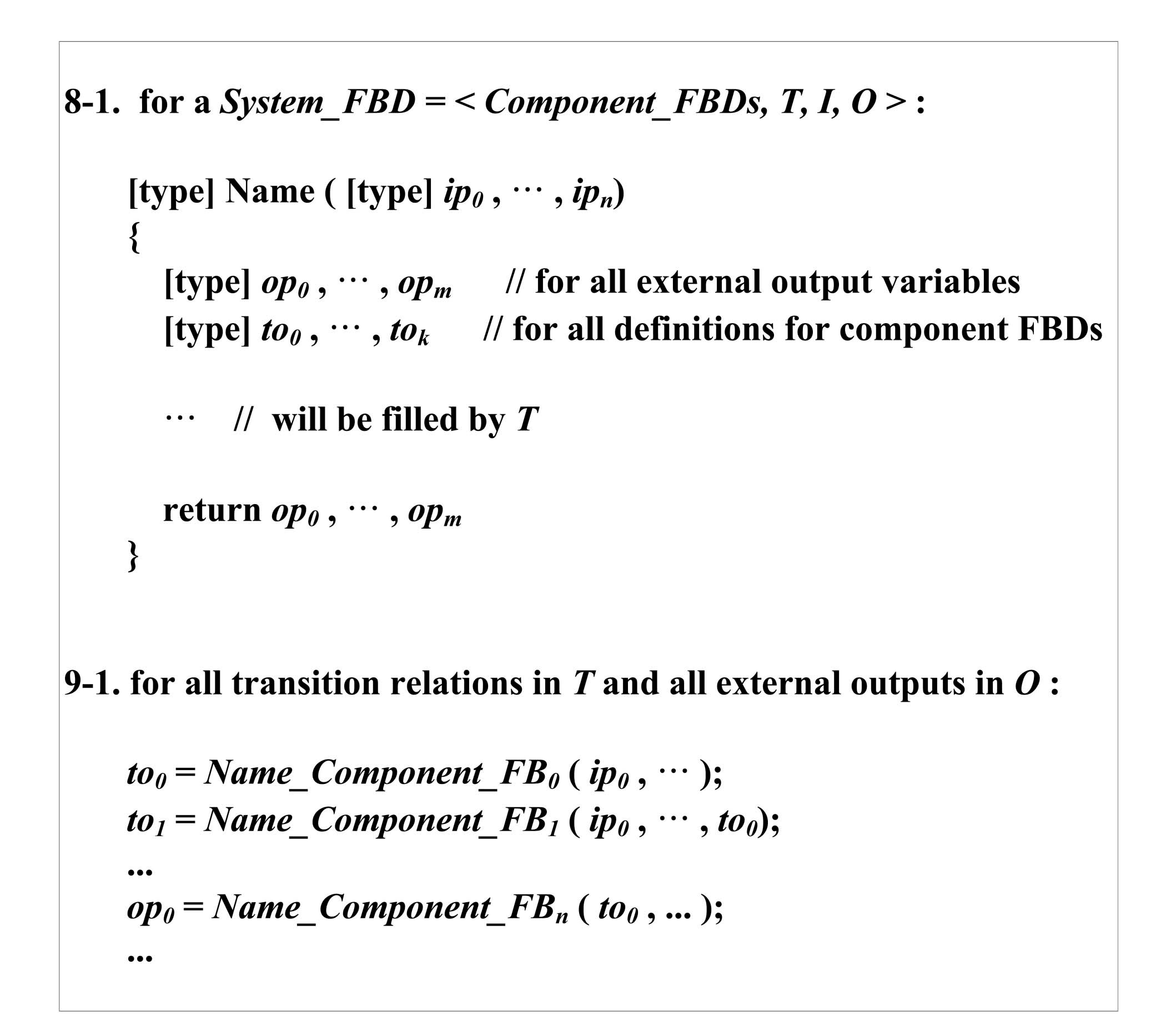
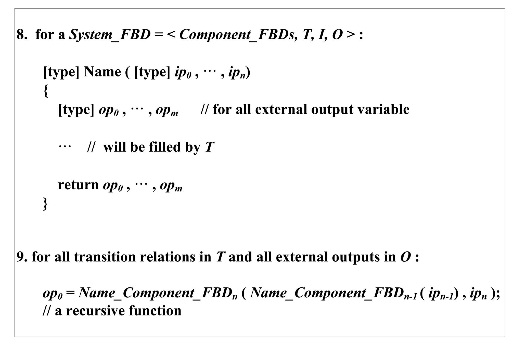
4.1.3 Translation of System FBDs
A system FBD is a set of component FBDs connected according to their sequential execution orders. Translation
rules for system FBDs are basically the same as those of component FBDs, but the former is composed of sequential function calls of component FBDs not individual function blocks. If the outputs of component FBDs are used as inputs of other component FBDs, as defined in
It is worth noting that the actual translation in practice may be different from the rules above and the algorithm in Fig.5. The rules above do not use temporary output variables, but just call all C functions for component FBDs backwardly. Our experiment and case study in Section 5, however, found that in-depth recursive function calls of the so-called ‘
4.1.4 Correctness of the Backward Translation
Correctness of the proposed translation algorithm and rules can be proven by showing that the FBD software system (Definition 4) has the same I/O behavior with the translated C program for all inputs.
Theorem 1. [Correctness of the Backward Translation]
Forward translation of FBDs into C programs is quite similar with the backward translation, but uses temporary output variables (TOVs) additionally. The backward translation is intuitive to understand since it follows the execution flow backwardly from outputs to inputs. However, several depths of recursive function calls make it difficult to thoroughly understand. The forward translation uses sufficient temporary variables to understand the C programs more easily.
4.2.1 Translation of Function Blocks
Translation of function blocks is the same as the backward translation, as shown in Fig.5.
4.2.2 Translation of Component FBDs
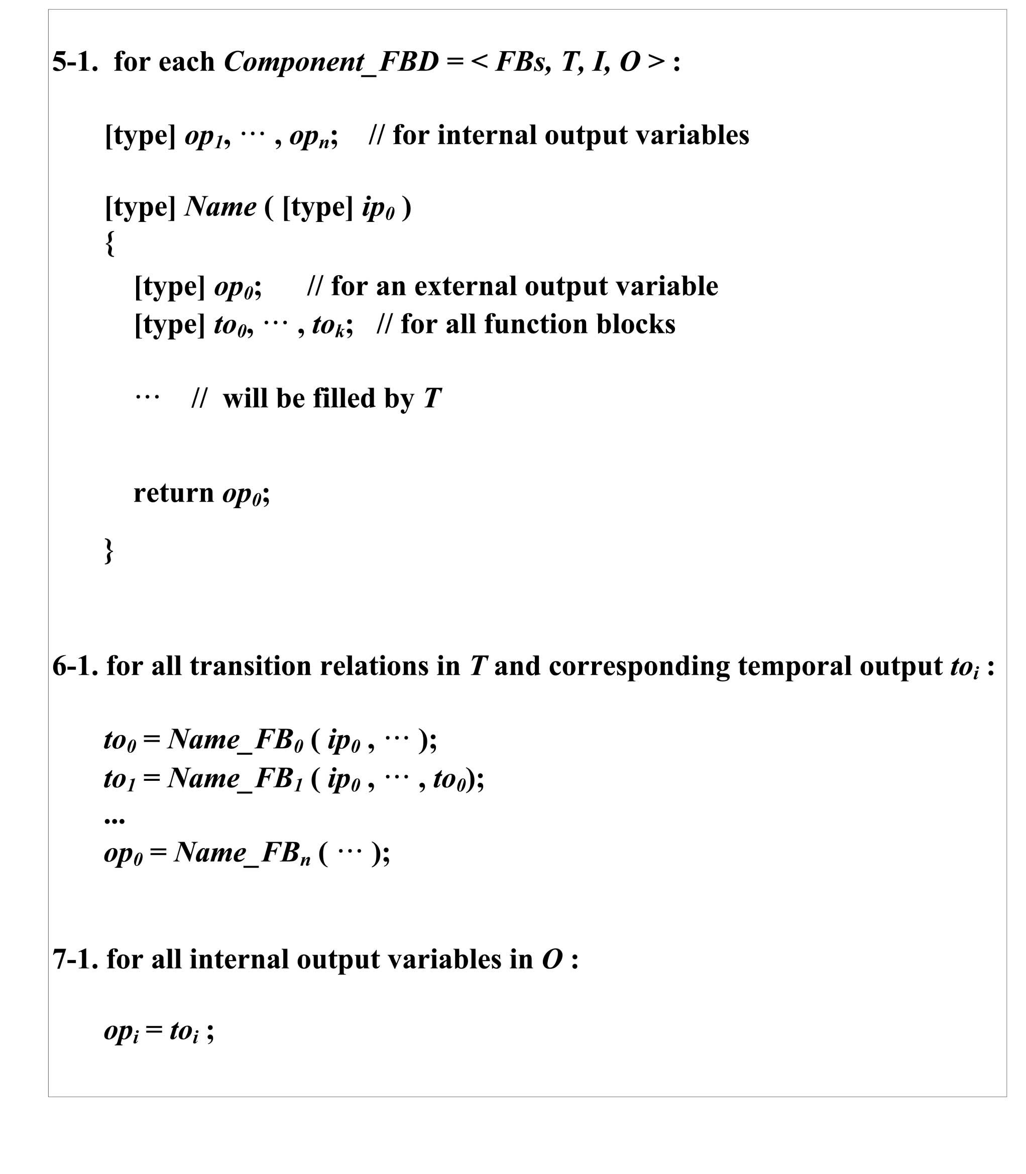
Fig.11 defines rules for component FBDs. These are basically the same as the backward translation, but the output value is calculated and assigned forwardly as defined in Rule 5-1. For each function block, we define a TOV (
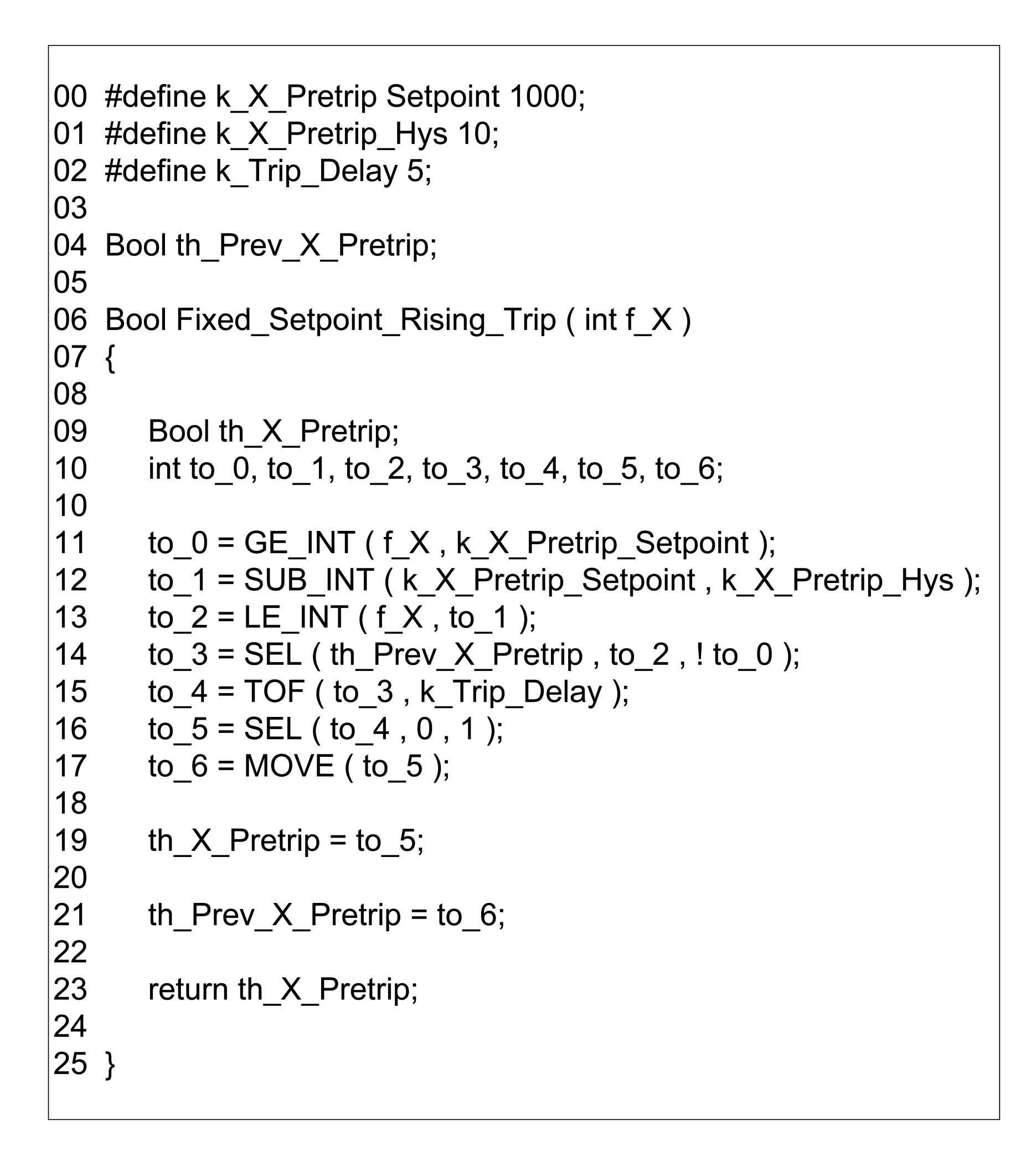
Fig.12 is an example of the C program translated forwardly according to the rules 5-1 ~ 7-1. It uses 7 TOVs (such as
The forward translation of component FBDs requires more lines of codes than the backward translation (
4.2.3 Translation of System FBDs
A system FBD is structured with a sequential set of interconnected component FBDs. The translation rules for system FBDs are similar with those for component FBDs, but they call the component FBDs according to their execution order forwardly and store their output values in TOVs. A detailed example of the forward translation can be found in the Appendix. Fig.13 defines the rules.
4.2.4 Correctness of the Forward Translation
Correctness of the proposed translation algorithm and rules in Section 4.2 can be proven by showing that the FBD software system (Definition 4) has the same I/O behavior for all inputs with the C program translated.
Theorem 2. [Correctness of the Forward Translation]
4.3 Practical Considerations on the Proposed Translations
When applying the translations to large and complex real-world systems such as RPSs in nuclear power plants, the following guidelines would be helpful.
C code optimization: The translated C program does not require code optimization since it intends to be implemented into PLC hardware not for formal verification purposes. The C programming language is more powerful and expressive than the design language FBD, and even more than the hardware description language such as Verilog and VHDL. Our former worker [26] for formal verification of FBD programs, the bit (space) optimization of translated code, was important to avoid the 'state explosion problem' [30] which make the algorithmic verification easily infeasible. This case intends behavior-preserving code generation for implementation purposes, not formal verification. Code optimization, therefore, would be better to focus on readability and understandability of the code for manual inter-checking rather than on code efficiency such as LOC (Line number Of Code) and execution time. The C compilers and the target hardware PLC are typically fast enough to load translated C programs without any optimization.
C code-based structural testing: The C program translated by the proposed technique is not useful for typical C code-based structural testing, especially for control flow coverage-based testing [20]. As it calls sub-functions sequentially according to a predefined execution order, forwardly or backwardly, it has no complex control loops such as 'for,' 'while' and 'goto.' Therefore, the typical control-flow based testing and coverage criteria (e.g., statement, branch, condition and MC/DC) are not effective for testing the translated C programs. A data-flow based testing and coverage criteria will be more helpful as analyzed in [31].
C code execution: The translated C program requires supplementary codes to be compiled, loaded and executed on PLC hardware. For example, an FBD software system (Definition 4) has a set of local timers and a global timer which synchronizes with a number of local clocks, and the translated C programs should take into account their synchronization. The internal output variables in Definition 4 are translated into global variables for component FBDs, (e.g., th_Prev_X_Pretrip in Fig.9 and Fig.12). The scoping of global variables generated for component FBDs should also be considered.
Extending to C++: Some important ideas of the objectoriented programming language [16] can be usefully adopted for translating basic function blocks. Development of real-world systems is apt to use various instances of a basic function block. For example, in case of ADD, we have to distinguish their variant, such as ADD with 2 integer inputs, 3 integer inputs and 2 Boolean inputs. A different C function should be defined and used for each variation. If we use an object-oriented programming language C++, variations can be defined more effectively. However, the choice of a programming language for PLCs depends not only on the efficiency and convenience of the language but also the correctness and safety level of its compiler, which has been proven.
Vendor-specific FBDs: PLC vendors such as AREVA and POSCO ICT maintain their own format and usage of FBD programming language. For example, the software engineering tool-set of POSCO ICT does not allow separated (i.e., not interconnected FBDs), but rather all connected FBDs only. It also uses interchangeably a mixture of FBD and LD. We should be able to take into account the software program which is a mixture of FBD and LD programming languages.
We applied the proposed translation techniques to a set of FBD programs for APR-1400 RPS BP in Korea. The RPS was developed by KNICS [9] project consortium and several export contracts have been undergoing. We use as an example of our case study the FBDs, which were mechanically generated from a formal requirement specification [13] written in NuSCR [18]. The project used the formal requirement specification for modeling RPSs efficiently and correctly as well as achieving diversity of software requirement specifications. The formal specification and its supporting tool-set generate FBD programs mechanically [32], and several formal verification techniques (
The mechanically generated FBDs in our case study are not the real ones used for developing the current (official) version of APR-1400 RPS, and were used when developing a prototype. They include approximately 50% more function blocks than the one developed manually by experts. However, they include all important and fundamental shutdown logics for the RPS. This case study sufficiently demonstrates that the translations proposed can work on real versions of FBDs as well as the mechanically translated ones.
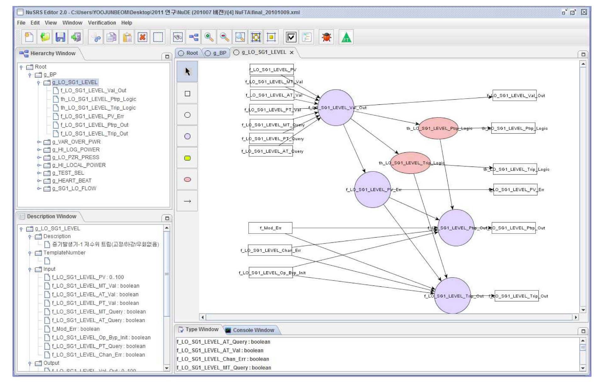
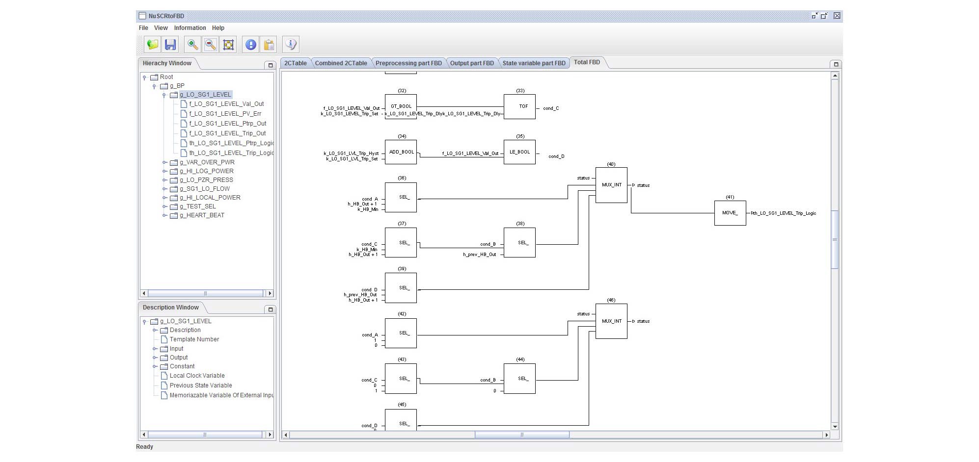
Fig. 14 shows the NuSCR specification while Fig. 15 depicts FBD programs mechanically translated from the
formal requirements specification. The directory information window at the left part of the tool-sets shows 8 shutdown logics for the RPS BP, which are categorized as follows. The whole RPS BP is composed of 18 logics, but the category below encompasses all the logics.
Fixed set-point logic: It has a fixed set-point of firing a shutdown signal. If an input value crosses the point in a rising or falling manner, the shutdown signal gets fired.
(e.g., g_LO_SG1_LEVEL, g_HI_LOG_POWER)
Variable set-point logic: It has a variable set-point of firing a shutdown signal, varying with the same (rising or falling) rate of the change of the input variable until a predefined fixed limit. If the varying rate of the input variable is more than the fixed limit, then the shutdown signal gets fired.
(e.g., g_VAR_OVER_PWR, g_SG1_LO_FLOW)
Manual reset logic: It has a fixed set-point of firing a shutdown signal, but an operator can delay the shutdown by moving the set-point to an upper point (in case of rising input flow) by pushing a reset button. The operator can push the reset button several times for specific purposes.
(e.g., g_LO_PZR_PRESS)
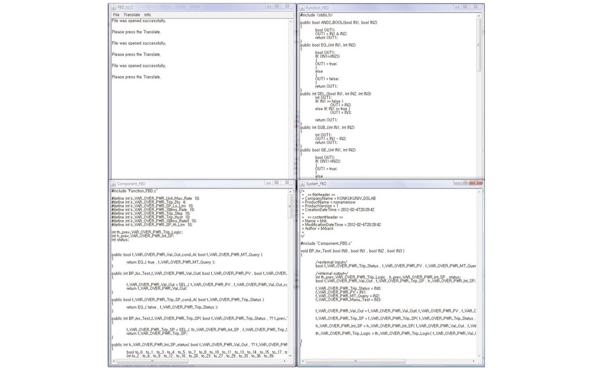
We applied the two translation techniques (the forward and backward translations) to the 6 logics of FBD programs shown in Fig.15, and compared them statically. We first developed a prototype of the FBD-to-C translator as depicted in Fig.16. Then we performed the forward and backward translations, and calculated detailed information such LOC and number of function blocks defined. It includes 4 windows; one for command information and others for three levels of translated C programs (
[Table 1.] Information of the FBDs
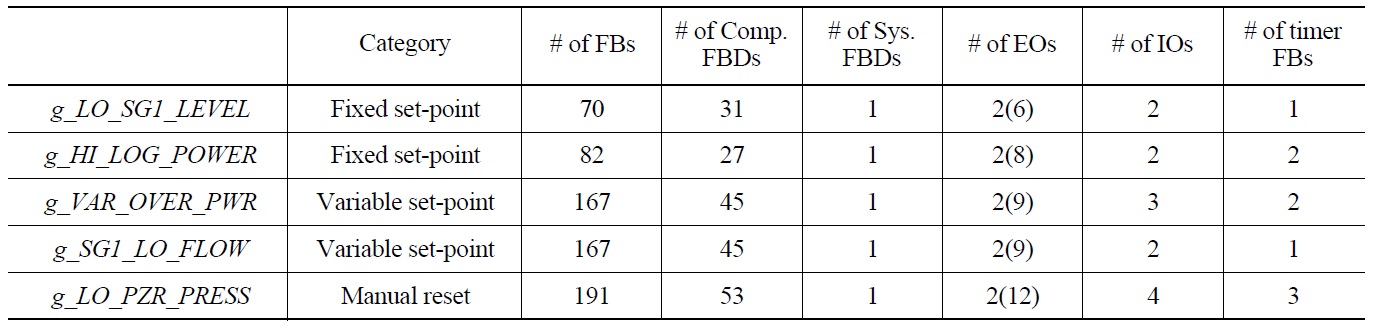
Information of the FBDs
presents the features of FBD programs in the RPS BP, which will be translated into C programs. As described in the table, the
Table 2 compares the two translation techniques. The LOC demonstrates that the forward translation requires more codes than the backward translation, since the latter uses multi-level function calls. The Maximum depth of nested function calls points their difference out clearly. The forward translation calls function at most in a depth of three (3), while the backward translation calls function at most in a depth of six (6). The one needs more lines to unroll the nested function calls while the other needs more endurance for reading and understanding. The Number of the 18 temporary variables used can be understood in a similar way.
'
[Table 2.] A comparison of the Forward and Backward Translations
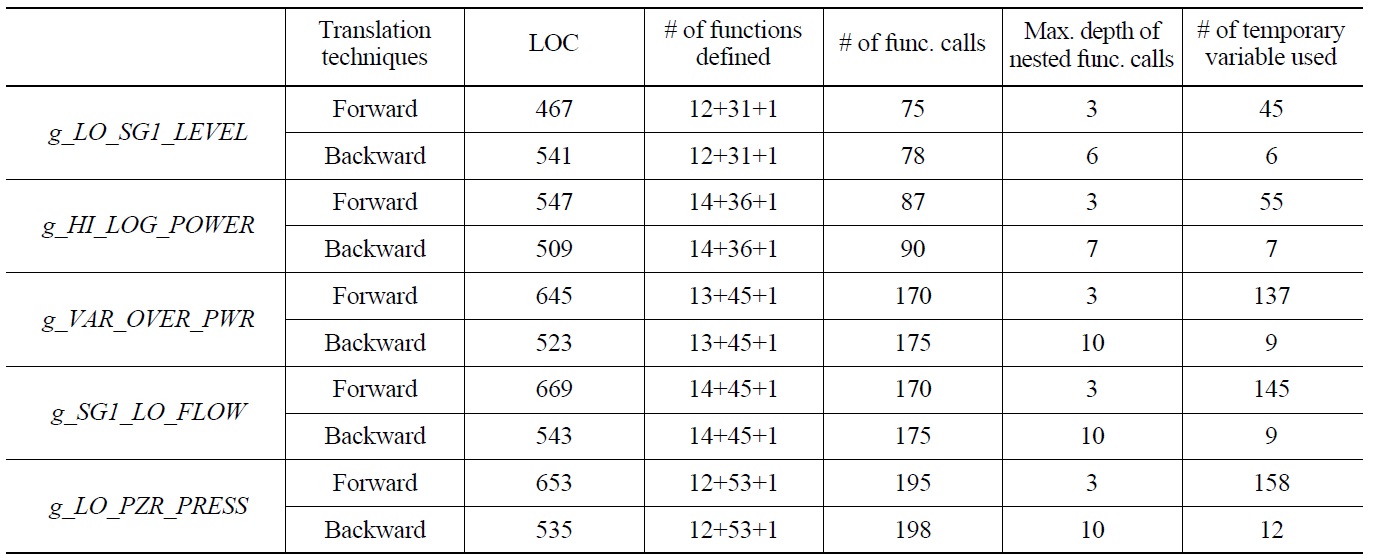
A comparison of the Forward and Backward Translations
with 12 different function blocks, 31 component FBDs and 1 system FBD, the C program is also composed of 44 functions in total.
The Appendix presents two C programs translated from the FBD of the
Embedded software for a nuclear reactor protection system requires rigorous demonstration of safety. This paper proposes two sets of translation algorithms and rules, which translate FBD programs in the design phase into C programs in the implementation phase, while preserving their behavioral equivalence. We used an example of RPS software in a Korean nuclear power plant to demonstrate correctness and to compare the proposed translations.
We are now planning to develop a translator for a specific PLC vendor to evaluate the proposed translation techniques dynamically as well as statically. It, however, will require more elaboration on the translations which this paper proposes, since vendor-specific features should be reconsidered. In addition, we are also planning to embed a prototype of the translator, which does not take into account vendorspecific factors, into our software development framework for RPSs,
A translation example: C programs for fixed set-point shutdown logic
A. The Forward Translation
/*component FBDs*/
...
/*f_LO_SG1_LEVEL_PV_Err*/
BOOL PV_Err_CondA(unsigned int f_LO_SG1_LEVEL_Val_Out){
return LT_BOOL(f_LO_SG1_LEVEL_Val_Out, k_LO_SG1_LEVEL_PV_Max);
}
BOOL PV_Err_CondB(unsigned int f_LO_SG1_LEVEL_Val_Out){
return GT_BOOL(f_LO_SG1_LEVEL_Val_Out, k_LO_SG1_LEVEL_PV_Min);
}
BOOL f_LO_SG1_LEVEL_PV_Err(unsigned int f_LO_SG1_LEVEL_Val_Out){
BOOL to_0;
to_0 = AND2_BOOL(!PV_Err_CondB(f_LO_SG1_LEVEL_Val_Out), !PV_Err_CondA(f_LO_SG1_LEVEL_Val_Out));
return SEL_(to_0, false, true);
}
/*f_LO_SG1_LEVEL_Ptrp_Out*/
BOOL Ptrp_Out_CondA(unsigned int th_LO_SG1_LEVEL_Ptrp_Logic){
return EQ_BOOL(true, th_LO_SG1_LEVEL_Ptrp_Logic);
}
BOOL Ptrp_Out_CondB(BOOL f_LO_SG1_LEVEL_Op_Byp_Init){
return EQ_BOOL(false, f_LO_SG1_LEVEL_Op_ Byp_Init);
}
BOOL Ptrp_Out_CondC(BOOL f_Mod_Err){ return EQ_BOOL(true, f_Mod_Err);
}
BOOL Ptrp_Out_CondD(BOOL f_LO_SG1_LEVEL_Chan_Err){
return EQ_BOOL(true, f_LO_SG1_LEVEL_Chan_Err);
}
BOOL Ptrp_Out_CondE(BOOL f_LO_SG1_LEVEL_PV_Err){
return EQ_BOOL(true, f_LO_SG1_LEVEL_PV_ Err);
}
BOOL f_LO_SG1_LEVEL_Ptrp_Out(unsigned int th_LO_SG1_LEVEL_Ptrp_Logic, BOOL f_Mod_Err, BOOL f_LO_SG1_LEVEL_Op_Byp_Init, BOOL f_LO_SG1_LEVEL _Chan_Err, BOOL f_LO_SG1 _LEVEL_PV_Err){
BOOL to_0, to_1, to_2, to_3, to_4;
to_0 = AND2_BOOL(Ptrp_Out_CondB(f_LO_SG1_LEVEL_Op_Byp_Init), Ptrp_Out_CondA (th_LO_SG1_LEVEL_Ptrp_Logic));
to_1 = OR2_BOOL(Ptrp_Out_CondE(f_LO_SG1_LEVEL_PV_Err), Ptrp_Out_CondD(f_LO_SG1_LEVEL_Chan_Err));
to_2 = OR2_BOOL(to_1, Ptrp_Out_CondC(f_Mod _Err));
to_3 = AND2_BOOL(to_2, to_0);
to_4 = SEL_(to_3, false, true);
return to_4;
}
...
typedef struct{
BOOL trip;
BOOL ptrp;
}Trip_signal;
/*system FBD*/
Trip_signal get_signal(unsigned int IN0, BOOL IN1, BOOL IN2, BOOL IN3, BOOL IN4, BOOL IN5, BOOL IN6, BOOL IN7, BOOL IN8, BOOL IN9, unsigned int IN10, unsigned int IN11, unsigned int IN12, unsigned int IN13){
Trip_signal *signal;
/*external input*/
unsigned int f_LO_SG1_LEVEL_PV;
BOOL f_LO_SG1_LEVEL_MT_Query, f_LO_SG1_LEVEL_AT_Query, f_LO_SG1_LEVEL_PT_Query;
BOOL f_LO_SG1_LEVEL_PT_Val, f_LO_SG1_LEVEL_AT_Val, f_LO_SG1_LEVEL_MT_Val;
BOOL f_LO_SG1_LEVEL_Op_Byp_Init, f_Mod_ Err, f_LO_SG1_LEVEL_Chan_Err;
/*external output variables for testing purposes*/
unsigned int Val_Out;
unsigned int Ptrp_Logic, Trip_Logic;
BOOL PV_Err;
/*assignment for external input values*/
f_LO_SG1_LEVEL_PV = IN0;
f_LO_SG1_LEVEL_MT_Query = IN1;
f_LO_SG1_LEVEL_AT_Query = IN2;
f_LO_SG1_LEVEL_PT_Query = IN3;
f_LO_SG1_LEVEL_PT_Val = IN4;
f_LO_SG1_LEVEL_AT_Val = IN5;
f_LO_SG1_LEVEL_MT_Val = IN6;
f_LO_SG1_LEVEL_Op_Byp_Init = IN7;
f_Mod_Err = IN8;
f_LO_SG1_LEVEL_Chan_Err = IN9;
/*executions of component FBDs*/
Val_Out = f_LO_SG1_LEVEL_Val_Out(f_LO_SG1 _LEVEL_MT_Query, f_LO_SG1_LEVEL_AT_Query, f_LO_SG1_LEVEL_PT_Query, f_LO_SG1_LEVEL_PV, f_LO_SG1_LEVEL_PT_Val, f_LO_SG1_LEVEL _AT_Val, f_LO_SG1_LEVEL_MT_Val);
Ptrp_Logic = th_LO_SG1_LEVEL_Ptrp_Logic (Val_Out); Set_Ptrp_Logic_Status(Val_Out);
PV_Err = f_LO_SG1_LEVEL_PV_Err(Val_Out);
signal->trip = f_LO_SG1_LEVEL_Trip_Out (Trip_Logic, f_LO_SG1_LEVEL_Op_Byp_Init, f_Mod_Err,
f_LO_SG1_LEVEL_Chan_Err, PV_Err);
signal->ptrp = f_LO_SG1_LEVEL_Ptrp_Out (Ptrp_ Logic, f_LO_SG1_LEVEL_Op_Byp_Init, f_Mod_Err,
f_LO_SG1_LEVEL_Chan_Err, PV_ Err);
return signal;
}
B. The Backward Translation
/*component FBDs*/
...
/*f_LO_SG1_LEVEL_PV_Err*/
BOOL PV_Err_CondA(unsigned int f_LO_SG1_LEVEL_Val_Out){
return LT_BOOL(f_LO_SG1_LEVEL_Val_Out, k_LO_SG1_LEVEL_PV_Max);
}
BOOL PV_Err_CondB(unsigned int f_LO_SG1_LEVEL_Val_Out){
return GT_BOOL(f_LO_SG1_LEVEL_Val_Out, k_LO_SG1_LEVEL_PV_Min);
}
BOOL f_LO_SG1_LEVEL_PV_Err(unsigned int f_LO_SG1_LEVEL_Val_Out){
return SEL_(AND2_BOOL(!PV_Err_CondB(f_LO_SG1_LEVEL_Val_Out), !PV_Err_CondA(f_LO_SG1_LEVEL_Val_Out)), false, true);
}
/*f_LO_SG1_LEVEL_Ptrp_Out*/
BOOL Ptrp_Out_CondA(unsigned int th_LO_SG1_LEVEL_Ptrp_Logic){
return EQ_BOOL(true, th_LO_SG1_LEVEL_Ptrp_Logic);
}
BOOL Ptrp_Out_CondB(BOOL f_LO_SG1_LEVEL_Op_Byp_Init){
return EQ_BOOL(false, f_LO_SG1_LEVEL_Op_Byp_Init);
}
BOOL Ptrp_Out_CondC(BOOL f_Mod_Err){ return EQ_BOOL(true, f_Mod_Err);
}
BOOL Ptrp_Out_CondD(BOOL f_LO_SG1_LEVEL_Chan_Err){
return EQ_BOOL(true, f_LO_SG1_LEVEL_Chan_Err);
}
BOOL Ptrp_Out_CondE(BOOL f_LO_SG1_LEVEL_PV_Err){
return EQ_BOOL(true, f_LO_SG1_LEVEL_PV_Err);
}
BOOL f_LO_SG1_LEVEL_Ptrp_Out(unsigned int th_LO_SG1_LEVEL_Ptrp_Logic, BOOL f_Mod_Err, BOOL f_LO_SG1_LEVEL_Op_Byp_Init, BOOL f_LO_SG1_LEVEL_Chan_Err, BOOL f_LO_SG1_LEVEL _PV_Err){
return SEL_(AND2_BOOL(OR2_BOOL( OR2_BOOL (Ptrp_Out_CondE(f_LO_SG1_LEVEL_PV_Err),
Ptrp_Out_CondD(f_LO_SG1_LEVEL_Chan_Err)), Ptrp_Out_CondC(f_Mod_Err)),
AND2_BOOL(Ptrp_Out_CondB(f_LO_SG1_LEVEL_Op_Byp_Init),
Ptrp_Out_CondA(th_LO_SG1_LEVEL_Ptrp_Logic))), false, true);
...
typedef struct{
BOOL trip;
BOOL ptrp;
}Trip_signal;
/*system FBD*/
Trip_signal get_signal(unsigned int IN0, BOOL IN1, BOOL IN2, BOOL IN3, BOOL IN4, BOOL IN5, BOOL IN6, BOOL IN7, BOOL IN8,BOOL IN9){
Trip_signal *signal;
/*external input*/
unsigned int f_LO_SG1_LEVEL_PV;
BOOL f_LO_SG1_LEVEL_MT_Query, f_LO_S G1_LEVEL_AT_Query, f_LO_SG1_LEVEL_PT_Query;
BOOL f_LO_SG1_LEVEL_PT_Val, f_LO_SG1_LEVEL_AT_Val, f_LO_SG1_LEVEL_MT_Val;
BOOL f_LO_SG1_LEVEL_Op_Byp_Init, f_Mod_ Err, f_LO_SG1_LEVEL_Chan_Err;
/*assignments for external input values*/
f_LO_SG1_LEVEL_PV = IN0;
f_LO_SG1_LEVEL_MT_Query = IN1;
f_LO_SG1_LEVEL_AT_Query = IN2;
f_LO_SG1_LEVEL_PT_Query = IN3;
f_LO_SG1_LEVEL_PT_Val = IN4;
f_LO_SG1_LEVEL_AT_Val = IN5;
f_LO_SG1_LEVEL_MT_Val = IN6;
f_LO_SG1_LEVEL_Op_Byp_Init = IN7;
f_Mod_Err = IN8;
f_LO_SG1_LEVEL_Chan_Err = IN9;
/*executions of component FBDs*/
Ptrp_Logic = th_LO_SG1_LEVEL_Ptrp0_Logic (Val _Out);
Set_Ptrp_Logic_Status(Val_Out);
PV_Err = f_LO_SG1_LEVEL_PV_Err(Val_Out);
/*assignments for external output variables*/
signal->trip = f_LO_SG1_LEVEL_Trip_Out( ... );
signal->ptrp = f_LO_SG1_LEVEL_Ptrp_Out( th_ LO_SG1_LEVEL_Ptrp_Logic(
f_LO_SG1_LEVEL_Val_Out(
f_LO_SG1_LEVEL_MT_Query,
f_LO_SG1_LEVEL_AT_Query,
f_LO_SG1_LEVEL_PT_Query,
f_LO_SG1_LEVEL_PV,
f_LO_SG1_LEVEL_PT_Val,
f_LO_SG1_LEVEL_AT_Val,
f_LO_SG1_LEVEL_MT_Val)),
f_Mod_Err,f_LO_SG1_LEVEL_Chan_Err, f_LO_SG1_LEVEL_PV_Err(
f_LO_SG1_LEVEL_Val_Out(
f_LO_SG1_LEVEL_MT_Query,
f_LO_SG1_LEVEL_AT_Query,
f_LO_SG1_LEVEL_PT_Query,
f_LO_SG1_LEVEL_PV,
f_LO_SG1_LEVEL_PT_Val,
f_LO_SG1_LEVEL_AT_Val,
f_LO_SG1_LEVEL_MT_Val)));
return signal;
}