검색 전체 메뉴
PDF
맨 위로
OA 학술지
A RESEARCH ON SEAMLESS PLATFORM CHANGE OF REACTOR PROTECTION SYSTEM FROM PLC TO FPGA
  • 비영리 CC BY-NC
  • 비영리 CC BY-NC
ABSTRACT
A RESEARCH ON SEAMLESS PLATFORM CHANGE OF REACTOR PROTECTION SYSTEM FROM PLC TO FPGA
KEYWORD
Embedded Software Development , PLC , FPGA , FBD , Verilog , Program Transformation
  • 1. INTRODUCTION

    A safety grade PLC is an industrial digital computer used to develop safety-critical systems such as RPS (Reactor Protection System) for nuclear power plants. The software loaded into a PLC is designed using specific PLC programming languages [1] such as FBD (Function Block Diagram) and LD (Ladder Diagram), which are then translated and compiled into a C program and executable machine code of a specific target PLC.

    Since the complexity of new RPSs and the maintenance cost of old RPSs have increased rapidly, we need to find an efficient alternative for the PLC-based RPS implementation. One solution [2,3] proposed is to replace PLC with FPGA, which can provide a powerful computation with lower hardware cost. However, it is a challenge for software engineers in the nuclear domain to abandoning all experience, knowledge and practice, based on PLC and start an FPGA-based development from scratch. Such change is also too risky from the viewpoint of safety. We need to transit to the new development approach safely and seamlessly, allowing all software engineers to become familiar with the processes and procedures required for a proper set up.

    This paper proposes an RPS software development process with a change in the hardware platform from PLC to FPGA.

    Itprovides the fundamentals for a seamless transition from PLC-based to FPGA-based development. We propose the use of FBD programs in the design phase of the existing PLC-based software development to produce the Verilog program, which is a starting point of typical FPGA developments. The 'FBDtoVerilog' mechanically transforms FBDs into behaviorally-equivalent [38] Verilog programs, and all V&V activities and safety analyses applied beforehand are still valid in the new hardware platform - FPGA. In order to demonstrate the effectiveness of the proposed approach, we performed a case study with an example of a preliminary version of RPS in a Korean nuclear power plant, from software requirements of PLC to netlists of FPGA.

    The paper is organized as follows: Section 2 introduces the FBD and Verilog programming languages, which are pertinent to our discussion. It also includes a brief introduction to PLC and FPGA. Section 3 explains the PLCbased RPS development in comparison with the FPGAbased development. It also introduces a typical RPS architecture to aid understanding. Section 4 proposes an RPS development process with changed platform from PLC to FPGA. Section 5 shows a case study, pointing out how the requirements and FBD designs of the existing PLC-based RPS software development can be effectively transformed into a starting point of the FPGA-based development. Related researches are surveyed in Section 6, and Section 7 concludes the paper and gives remarks on future research.

    2. BACKGROUND

       2.1 PLC

    A PLC (Programmable Logic Controller) [4] is a digital computer used in the automation of electromechanical processes. It is designed for multiple input and output arrangements, immunity to electrical noise and resistance to vibration. It is a good example of a hard real-time system, since output results must be produced in response to input conditions within a limited time, otherwise unintended operation will result.

    A PLC has a relatively simple architecture, compared to naive computers and servers using state-of-the-art microprocessors and supporting hardware. Sensors and actuators are plugged in via input and output channels, respectively. The operating system, managing periodic execution of PLC applications, reads all input values at the beginning of each cycle, generates required outputs, and stores system variables. Software embedded in the PLC is programmed with the five PLC programming languages defined by IEC 61131-3 [1], e.g., FBD and LD.

    A safety grade PLC is required for safety-critical systems by IEEE 7-4.3.2 [5], EPRI TR-107330 [6] and etc. Several vendors provide safety-level PLCs for nuclear reactor protection systems, such as AREVA (http://www.areva.com), invensys (http://iom.invensys.com) and POSCO ICT (http://www.poscoict.co.kr). All of these vendors provide their own PLC software engineering tool-sets for modeling, verification, simulation, testing and the generation of executable codes.

       2.2 FPGA

    An FPGA (Field-Programmable Gate Array) [7,8] is an integrated circuit, designed to be configured by a customer or a designer after being manufactured in field. The FPGA configuration (i.e., modeling) is generally specified using a hardware description language (HDL). FPGAs can be used to implement any logical function normally performed by an ASIC. The ability to update the functionality after shipping, partial re-configuration of a portion of the design, and the low non-recurring engineering costs relative to an ASIC design offer advantages for many applications. Many vendors provide various types of FPGA in industry; Xilinx, Altera, Lattice, Semiconductor, Actel, Cypress, QuickLogic and Atmel are some examples. The nuclear industry has tried to use the products of Altera and Actel.

       2.3 FBD

    An FBD, one of the widely used PLC programming languages, consists of an arbitrary number of function blocks, 'wired' together in a manner similar to a circuit diagram. The international standard IEC 61131-3 [1] defines 10 categories and all corresponding function blocks. For example, SUB_INT function block in Fig.1 performs arithmetic subtraction of two integer inputs.

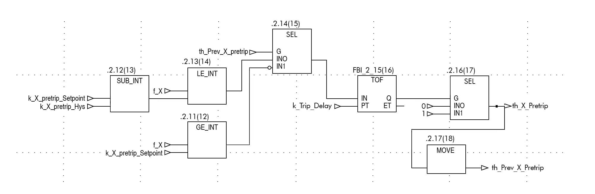
    Fig.1 shows a part of preliminary FBD programs for the KNICS RPS BP (Bistable Processor) [9]. It creates a signal 'th_X_Pretrip' when a trip (i.e., shutdown of nuclear reactor) condition has been satisfied for k_Trip_Delay time units, as implemented in the TOF timer function block. It is a warning signal fired before the real one (i.e., th_X_Trip). The number in parenthesis above each function block denotes its execution order. For example, GE_INT numbered (12) is the first function block executed, while MOVE numbered (18) is the last one. A large number of FBDs similar to Fig.1 are assembled hierarchically and executed according to a predefined sequential execution order. [10] includes a formal definition of function block diagram in details.

       2.4 Verilog

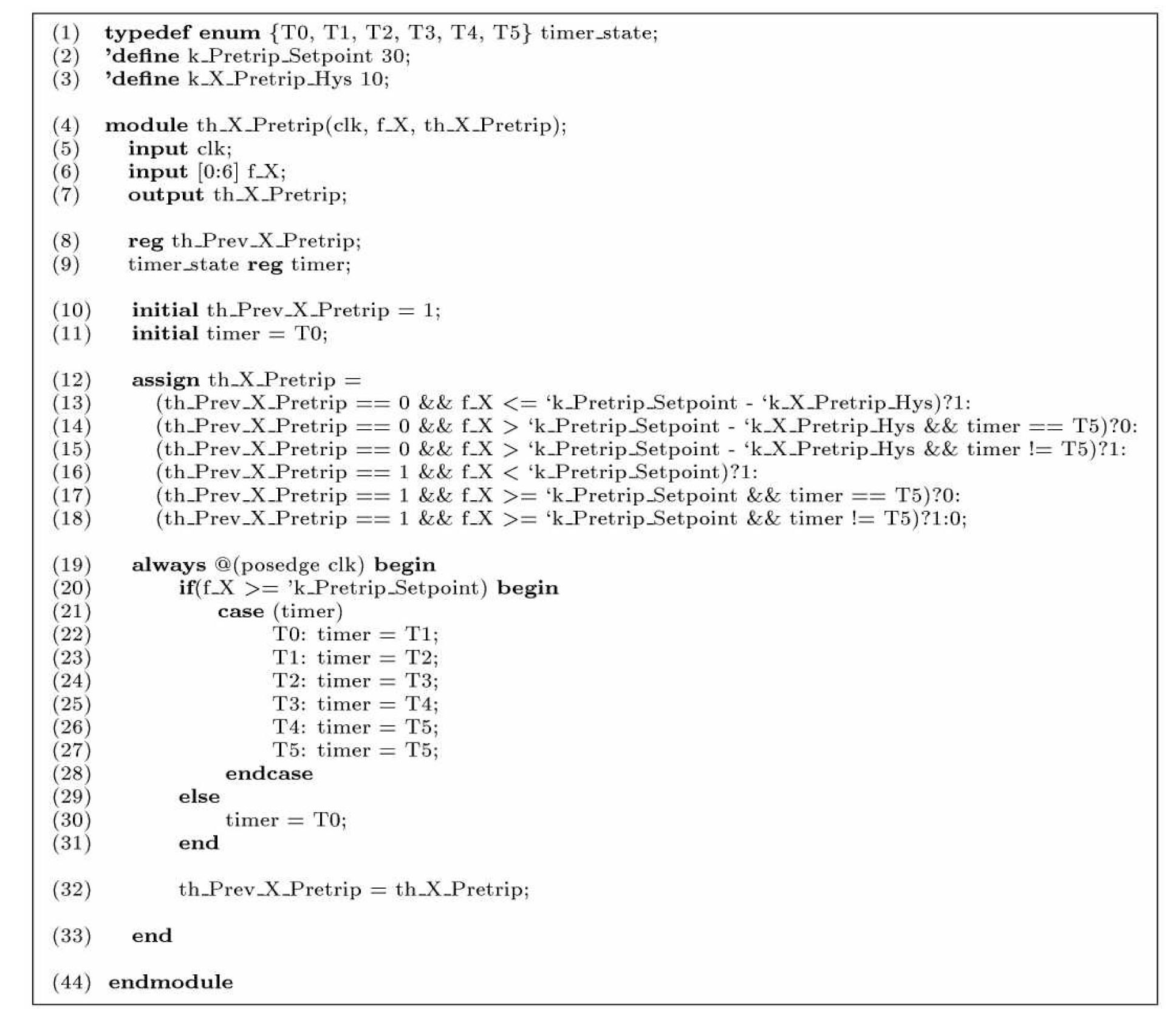
    Verilog is one of the most common HDLs (Hardware Description Languages) used by IC (Integrated Circuit) designers. Designs (i.e., hardware configuration) described in Verilog are technology independent, easy to develop and debug, and considered more readable than schematics for ICs. Fig.2 shows a Verilog program translated from the FBD (Fig.1) according to the translation rules proposed in [10], both showing identical behavior.

    The Verilog program in Fig.2 has two inputs (clk and f_X) and one output (th_X_Pretrip). th_Prev_X_Pretrip stores the value of th_X_Pretrip as defined by the MOVE function block in the FBD. The FBD's output th_X_Pretrip is produced in the assign statement (12) ~ (18). It also uses a reg variable timer to emulate the TOF function block as the always statements (19) ~ (31). This example restricts the number of internal states of TOF to 6, for convenience, as defined in (1). It also uses the clk variable to perform a synchronized operation.

    3. THE RPS SOFTWARE DEVELOPMENT PROCESSES

    This section explains two RPS software development processes, a typical one using PLC and a new approach using FPGA. The new one, however, has not been fully implemented and verified yet [11,12,13]. This section also includes a brief introduction to the KNICS RPS to aid understanding of the RPS development processes.

       3.1 An Overview of the KNICS RPS

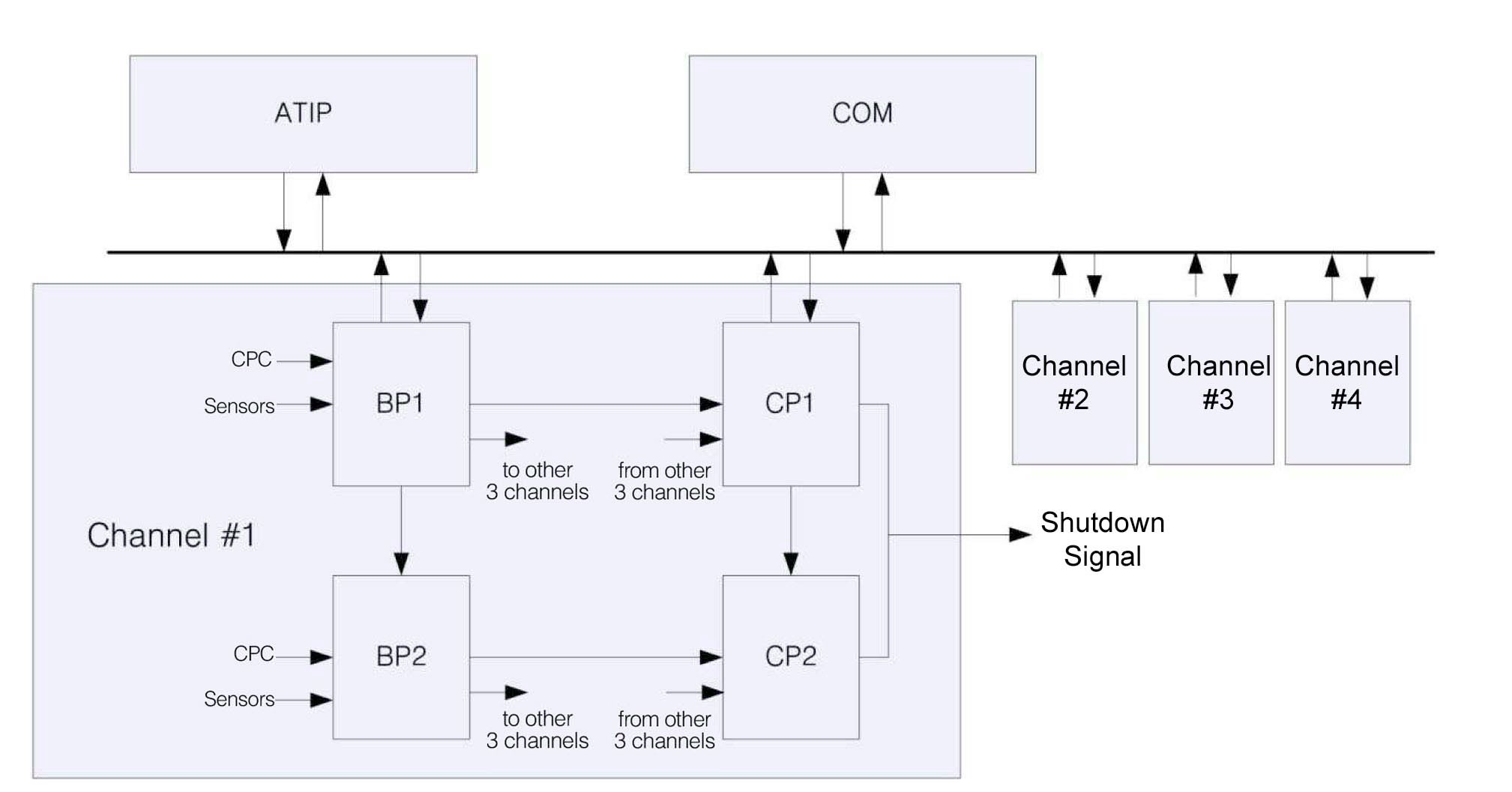
    The KNICS RPS (APR-1400 [14]) is a digital system in charge of safely shutting down a nuclear reactor in case of emergency. It has been approved for operational fitness evaluation tests in two nuclear power plants being built in Korea. As a safety-critical system, it has 4 redundant and physically isolated channels to provide defense in depth. A high-level architecture diagram1 for a single channel, shown in Fig.3, consists of two bistable processors (BPs), two coincidence processors (CPs), an automatic test and interface processor (ATIP) as well as a cabinet operator module (COM). The subsystems are interconnected with different networks. One BP is implemented into one PLC.

    The case study in Section 5 uses 6 representative shutdown logics in use by the BPs.

    A BP generates a trip signal to the CPs by comparing values of 18 process variables against predefined threshold values. There are four different trip logics built in the system: (1) fixed set-point trip (for 10 input variables); (2) variable set-point trip (3 variables); (3) manual reset trip (3 variables); and (4) digital trip (2 variables). The details of the logics will be explained in Section 5.1.2.

    Upon receiving trip signals, CPs execute two-out-offour voting logic to determine if the trip signal should be sent to the hardware actuators. All RPS channels are duplicated, and each one has two independent BPs and CPs respectively. ATIP, primarily used for either manual or automated tests initiated by operators, interacts with BP or CP in a single channel or multiple channels as a whole through the common bus. The COM, located in a operator room and connected to other processors through the common bus, has two parts: (1) a computer-based unit which provides status information regarding the overall RPS equipment, and (2) a hardware unit which performs protectionrelated controls such as channel bypass and initiation circuit reset.

       3.2 A Typical PLC-based RPS Software Development

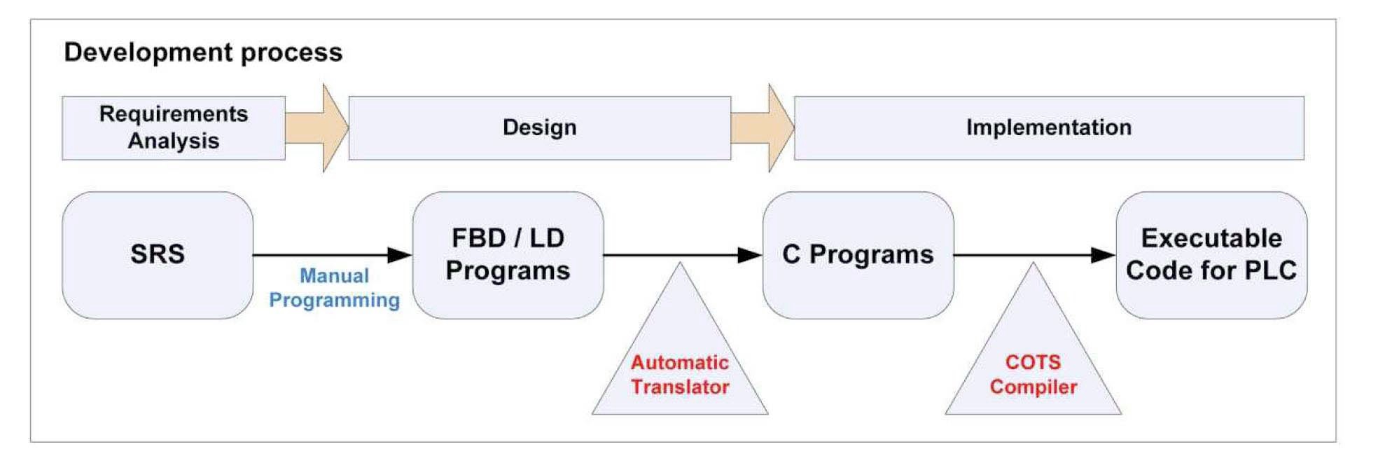
    An RPS is a real-time embedded system implemented on a number of PLCs. The RPS software is designed in FBD/LD languages and then translated into C programs, which will be compiled and loaded on PLCs. Fig.4 explains a typical software development process for RPSs.

    The SRS (Software Requirements Specification) is first written in natural languages or formal specification languages [16,17,18]. Experts on PLC programming languages then manually translate the requirements specification into design models programmed in FBD or LD. In case of the NuSCR [17] formal requirements specification [19], a CASE tool 'NuSCRtoFBD' [20] can translate the requirements into FBD programs mechanically. The mechanical translator, however, cannot encompass design /implementation-specific considerations, which are manually

    performed by software engineers, such as mapping of I/O and memory addresses.

    PLC vendors provide their own automatic translators from the FBD/LD programs into ANSI C programs, while typically using the COTS (Commercial Off-the-Shelf) software such as 'TMS320C55x' of Texas Instruments [21] for the C compilers. The COTS compilers were well verified and certified enough to be used without additional verification effort. However, the vendor-provided automatic translators should rigorously demonstrate functional correctness.

    Vendors such as AREVA, invensys and POSCO ICT have provided safety grade PLCs and their own software engineering tool-sets for nuclear reactor protection systems. 'SPACE' [22] is a software engineering tool-set for AREVA's PLC 'TELEPERM XS' [23]. It stores FBD programs into a database 'INGRES' and generates ANSI C programs to perform code-based testing and simulation ('TXS SIVAT' [24]). For the checking of consistency between FBD programs and generated C programs, the ISTec GmbH (http://www.istec.de) had developed a reverse engineering tool 'RETRANS' [25]. The mechanical translator in 'SPACE' has been validated in such ways, and the software engineering tool-sets have been used successfully for more than a decade.

    PLCs of invensys and its software engineering tool-set 'TriStation 1131' [26] also have been used widely. It provides enhanced emulation-based testing and real-time simulation of FBDs, but does not yet introduce a translator into C programs. KNICS and POSCO ICT in Korea have recently developed a safety-level PLC 'POSAFE-Q' and its software engineering tool-set 'pSET' [27]. The tool-set provides a graphical editor for FBD and LD programming languages and generates ANSI-C programs mechanically. However, sufficient demonstration of correctness and functional safety [57] of the so-called 'FBD-to-C' translator is still in progress. It must be one of the most critical obstacles that should pass through to get permissions for the export of the new Korean nuclear power plant [28] as a whole, i.e., including control software - I&C (Instrumentation & Control).

       3.3 An FPGA-based RPS Development

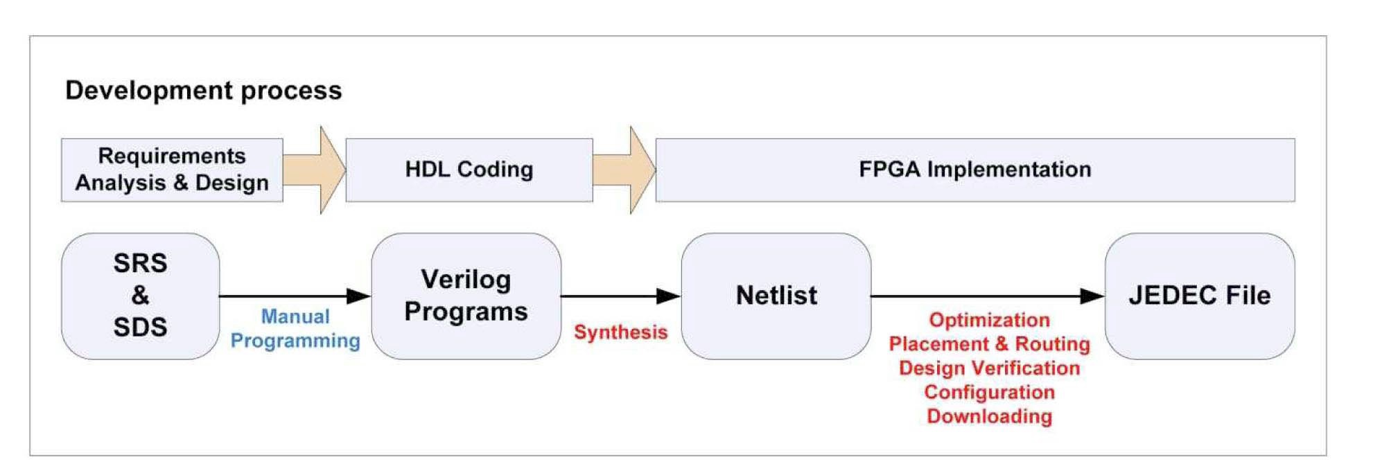
    Fig.5 depicts a whole FPGA development process [7] from the viewpoint of software engineers. Software (i.e., for RPS) requirements are analyzed and refined in requirements analysis and design phases, similar to the PLCbased development. Whereas the PLC-based development uses FBD programs as a design specification, it provides no standard form of requirements and design specifications. In HDL (Hardware Design Language) code phase, we need to manually program the designs in HDLs such as Verilog or VHDL. Some FPGA vendors provide their own high-level design tools [29], which use flow-charts, state machines or block diagrams and can generate HDL designs mechanically.

    After programming the Verilog (or VHDL) programs, an FPGA is produced mechanically thorough several steps: synthesis, optimization, placement & routing, design verification, configuration and downloading. Software synthesis tools provided by FPGA vendors such as 'Xilinx ISE Design Suite' [30] and 'Altera Quartus II' [31] support all steps seamlessly and mechanically. They also provide systematic verification and simulation facilities for each synthesis step.

    FPGA is not widely used for implementing safetycritical controllers in RPS, since software engineers in the nuclear domain are not familiar with its development process and techniques. Implementation of the whole RPS with a number of FPGAs also goes with an all-new architecture. Safety demonstration of FPGA up to the level of PLC is also an obstacle for easy-application of FPGA. Section 5.3 shares our further consideration on the FPGA as a means to implement RPSs.

    1 Fig.3 represents a preliminary design. The certified design was modified.

    4. THE RPS SOFTWARE DEVELOPMENT WITH PLATFORM CHANGE

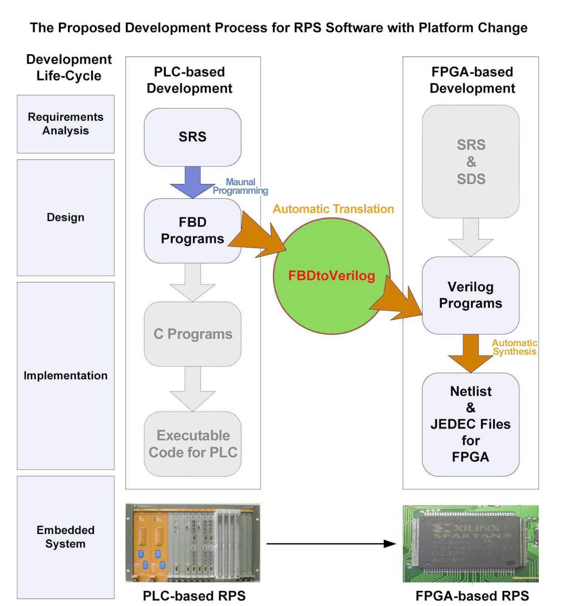
    This paper proposes a new process for the development of software for the use with protection systems designed for nuclear reactors. It aims for the seamless and safe transition from the PLC-based development to the FPGA-based one in case that the embedded hardware platform changes

    from PLC to FPGA. The development process is introduced first and is followed by an explanation on 'FBDtoVerilog,' which brides the two RPS software development processes.

       4.1 A New Software Development Process for RPS

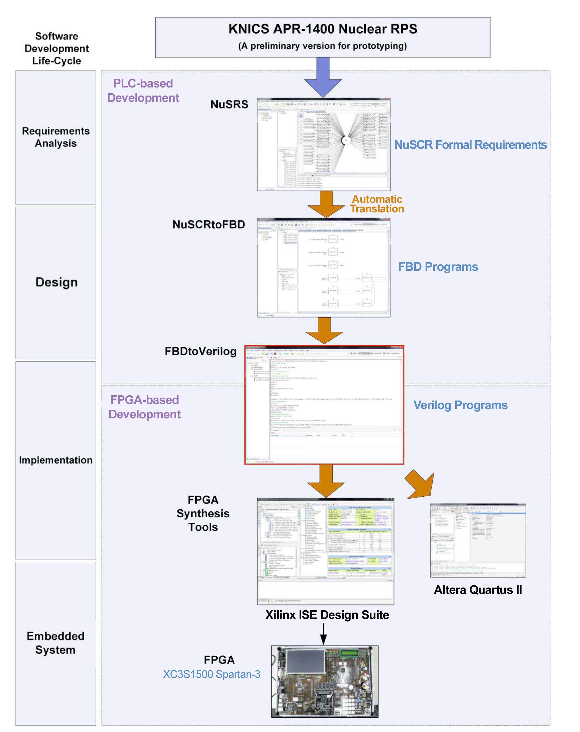
    Our goal is to replace the embedded hardware platform of RPS - PLC with FPGA, while maintaining all knowledge, experience and practice accumulated so far. Another goal of this research is to Prevent potential errors caused by software engineers who are not familiar with the new FPGAbased development. This paper proposes a new RPS software development process, as summarized in Fig.6. It can bridge the two RPS software development processes seamlessly and safely, while using all knowledge of the old PLC-based development and moving to the new FPGA-based development.

    The proposed process first follows the PLC-based software development summarized in Fig.4, up to the design phase. Software requirements are analyzed and specified first, and then design specifications of FBD programs are produced manually, same as before. All V&V activities and safety analyses in the PLC-based development (e.g., those in [18]) are also performed and applied. The 'FBDtoVerilog' translator then transforms the verified FBD program into a behaviorally-equivalent Verilog program, which corresponds to the HDL coding phase in the FPGA-based development depicted in Fig.5. The RPS software development now transits seamlessly from the PLC-based to the FPGA-based development. All activities left in producing an FPGA is the role of FPGA synthesis tools provided by FPGA vendors.

    The 'FBDtoVerilog' enables us to overcome the gap between two different platform-based RPS developments by translating design models of the old into behaviorallyequivalent HDL models of the new. This paper uses a refined and improved version of the 'FBDtoVerilog' translator, which had been developed for several purposes [10,32,33,34]. The following section will focus on the detailed explanation of the above mentioned translator.

       4.2 FBDtoVerilog

    The 'FBDtoVerilog' is an automatic translator, from FBD programs into behaviorally-equivalent Verilog programs. We have developed several versions of the 'FBD toVerilog' for different purposes, such as formal verification of FBD designs and indirect verification of the 'FBDtoC' translator. An overall explanation on the previous versions is introduced first, and new features of the proposed version is then followed.

    Our first work 'FBDVerifier' [33] aimed to verify an FBD program using the SMV model checker [35]. It translates an FBD program into a behaviorally-equivalent Verilog program and executes SMV seamlessly. It also provides a visual analysis on the verification results (i.e., LTL model checking [36] and counter-examples). SMV regards all Verilog programs as Synchronous Verilog (SV) [37], and we had to resolve the concern over the unexpected conversion of synchronous and asynchronous behavior.

    The next versions [10,32] aims to verify FBD programs with the VIS verification system [38]. These also separate the so-called 'FBDtoVerilog' translator from specific FBD formats of PLC vendors. They read FBD programs which follow the de facto standard of PLCopen TC6 [39], not a vendor-specific FBD format. Since VIS is a synthesis and verification tool for IC development, its input programming language - Verilog is more primitive, sensitive and detailed than that of SMV. For example, if two Verilog variables under equivalence checking do not have the same size in bits, VIS often produces a wrong calculation result, not an error.

    The 'FBDtoVerilog' translator in [34] tried to verify the functional correctness of the 'FBDtoC' translator, indirectly. PLC vendors provide their own FBDtoC translator and have verified and demonstrated function correctness of the translators in various ways, as explained in Section 3.1. We tried to translate FBD programs into behaviorallyequivalent Verilog programs first, and performed the HWCBMC [40] verification which checks the functional equivalence between Verilog programs and C programs. The translation rules for the HW-CBMC verification use the Verilog module as a unit of translation, since HWCBMC cannot read the Verilog function which is the basic unit of the previous translations.

    The former 'FBDtoVerilog' translators all aim at the formal verification of FBD programs by translating FBDs into behaviorally equivalent Verilog programs, even if diverse formal verification tools are used such as SMV, VIS and HW-CBMC. Therefore, due to the inherent limitation of model checking techniques [41], the size of FBD program is not large. They all consider about only an individual reactor shutdown logic of 100 ~ 200 function blocks.

    This paper, however, uses the translator for the purpose of development, not formal verification. We had to scale up the translation capability from an individual shutdown logic to a whole RPS BP, structuring with 18 logics. The scale-up accompanies refinement of the translator as follows:

    Variable renaming : Systematic renaming of component FBDs and intermediate/external outputs, and restructuring of internal data structures are required to translate multiple depths of RPS hierarchy.

    Explicit type conversion : With some cases, implicit type conversion does not word correctly. All type conversions now use explicitly function blocks of type conversion (e.g., integer-to-boolean or vise versa).

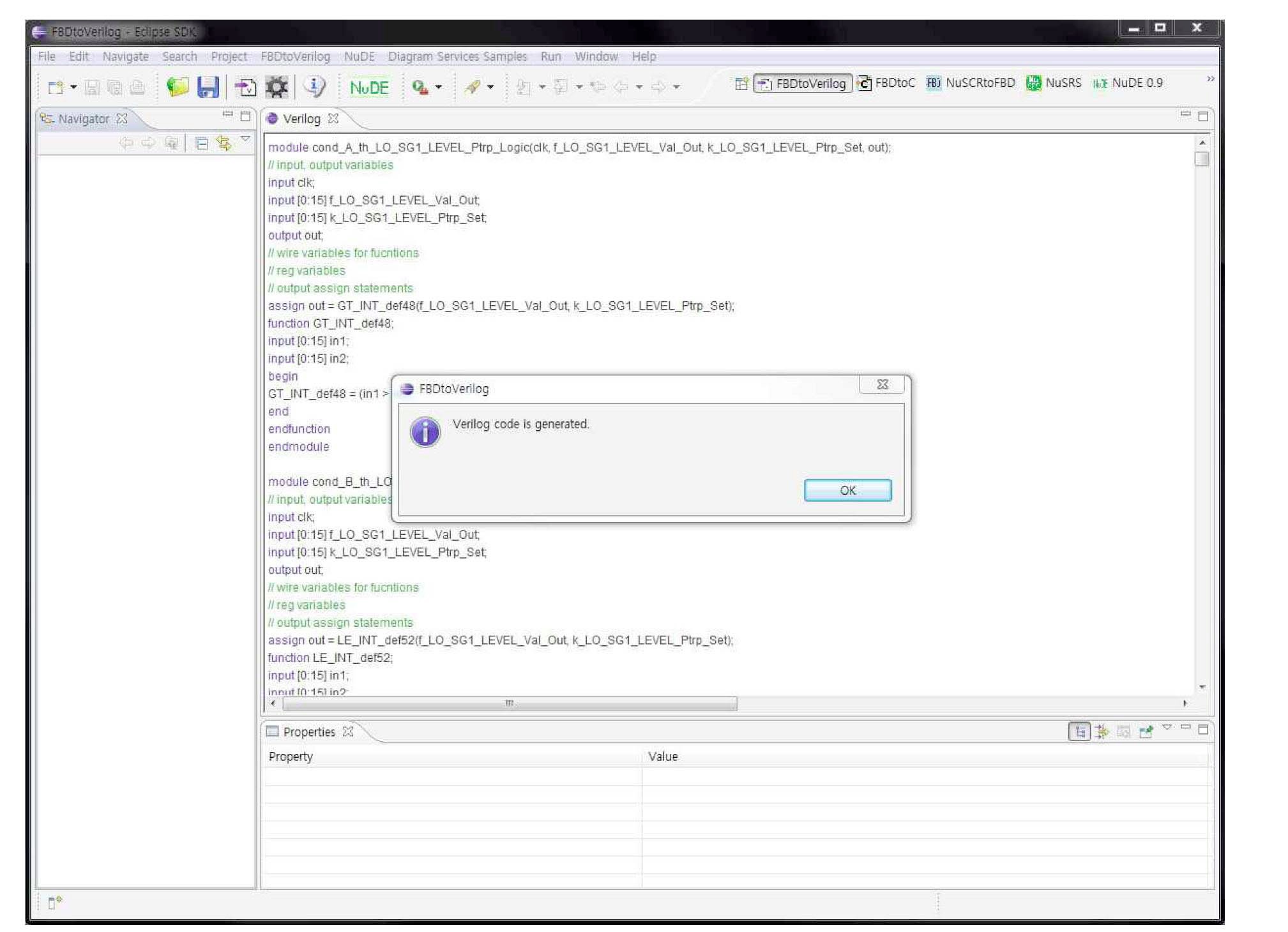
    Eclipse plug-in : The new 'FBDtoVerilog' has been re-implemented as an independent Eclipse plug-in in order to be integrated intimately with other software engineering tools in the 'NuDE' environment [42].

    This paper developed a new version of 'FBDtoVerilog' as shown in Fig.7. It reflects the scale-up issues above all, and was also developed as an Eclipse plug-in. Former versions are all JAVA applications. Whereas former versions were embedded in 'NuSCRtoFBD' [18] or 'FBDVerifier' and called internally for the purpose of formal verification, the current one is an individual and independent tool, supporting the design/implementation phase for FPGA development as well as the FBD verification. It can read an FBD program of standard XML format defined by PLCopen and produce a behaviorally-equivalent Verilog program. Any FBD program which follows the TC6 standard of PLCopen can be translated into an equivalent Verilog program. For example, 'pSET2TC6' [43] is a translator for the software engineering tool 'pSET' of POSCO ICT. It reads an output file of 'pSET' and translates it into an FBD program of the PLCopen TC6. The new 'FBDtoVerilog' also can read an FBD system, which is hierarchically structured with more than 1,000 function blocks, and produces one Verilog program for the whole FBD system.

    5. CASE STUDY

    This section demonstrates the effectiveness of the proposed RPS software development process, which can seamlessly transit from the PLC-based to the FPGA-based development. Section 5.1 explains the whole process of performing the case study, according to the software development life-cycle (SDLC). Section 5.2 includes an explanation of the detailed features of the FPGA synthesis as well as its sources such as FBD and Verilog programs. Section 5.3 includes our further consideration on the proposed process in order to apply it to an actual RPS development.

       5.1 Case Study Plan

    Fig.8 describes the whole process of our case study. We applied the new RPS software development process to a preliminary version of the KNICS APR-1400 RPS BP in Korea [14]. The RPS was developed by the KNICS [9] project consortium and several export contracts have been undergoing. The case study demonstrates that, proceeding with the software development life-cycle, the RPS software development allows for a smooth transition from the PLCbased development to the FPGA-based one.

    5.1.1 Requirements Analysis

    The case study starts from a formal requirements specification [19] written in NuSCR [17]. The KNICS project consortium used the formal requirement specification to achieve diversity of software requirements specifications. It was developed for prototyping purpose, but modeled all shutdown logics of the RPS BP completely. Its supporting tool-sets ('NuSRS' and 'NuSCRtoFBD') generate behaviorally- equivalent FBD programs mechanically [20]. Formal verification techniques (e.g., model checking and equivalence checking) and safety analyses can also be applied to the requirements [18]. The tool-sets have been re-implemented in order to be integrated into a new development environment, called 'NuDE' [42].

    5.1.2 Design

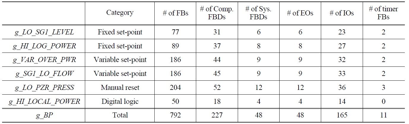
    The mechanically generated FBD is structured with more function blocks than the one developed by experts manually, about 50%. However, it includes all important and fundamental shutdown logics for the RPS BP. This case study uses 6 shutdown logics as the directory information window at the left part of 'NuSCRtoFBD' shows. The whole RPS BP is composed of 18 logics, but the category below encompasses all the logics.

    Fixed set-point logic : It has a fixed set-point of firing a shutdown signal. If an input value crosses the point in rising or falling manner, the shutdown signal is fired.

    (e.g., g_LO_SG1_LEVEL , g_HI_LOG_POWER)

    Variable set-point logic : It has a variable set-point of firing a shutdown signal, varying with the same (rising or falling) rate of the change of input variable until a predefined fixed limit. If the varying rate of the input variable is more than the fixed limit, the shutdown signal is fired.

    (e.g., g_VAR_OVER_PWR , g_SG1_LO_FLOW)

    Manual reset logic : It has a fixed set-point of firing a shutdown signal, but an operator can delay the shutdown by moving the set-point to an upper point (in case of a rising input flow) by pushing a reset button. The operator can push the reset button several times for specific purposes.

    (e.g., g_LO_PZR_PRESS)

    Digital logic : It is called a 'digital trip.' It does not check whether it has to fire or not a shutdown signal, but just passes an input signal (0 or 1) to output. An input or output of 0 will lead to a shutdown signal. Different from other shutdown logics, other logic prior to the BP calculates the shutdown condition and just passes the result to it.

    (e.g., g_HI_LOCAL_POWER)

    5.1.3 Between Design and Implementation

    The actual software development of typical PLC-based approaches is nearly concluded in the design phase, since PLC vendors' software engineering tools translate those FBDs into C programs and compile them into executable machine codes for specific PLCs, mechanically. At the design phase of the PLC-based development, the new development process transits to the FPGA- based development seamlessly thorough the 'FBDtoVerilog.'

    The 'FBDtoVerilog' translates the whole FBD programs into a Verilog program, mechanically. It reads FBD programs in the standard XML format of PLCopen, and produces a behaviorally-equivalent Verilog program which the FPGA synthesis tools can read accurately. As we mentioned in Section 4.2, the new 'FBDtoVerilog' translator is now not a verification-supporting tool but a development (implementation) tool. The scale-up issues were considered carefully and re-implemented as an independent Eclipse plugin as shown in Fig.8.

    5.1.4 FPGA Implementation

    The Verilog program translated from the FBD programs by the new 'FBDtoVerilog' is a starting point of the FPGAbased development. The case study uses two automatic synthesis tools, 'Xilinx ISE Design Suite' [30] and 'Altera Quartus II' [31], to produce netlists and JEDEC files. The research also used an FPGA development platform of 'Xilinx XC3S1500 Spartan' and produced an FPGA for

    [Table 1.] A Feature of the FBD Program used

    label

    A Feature of the FBD Program used

    the 6 logics of the KNICS RPS BP. Detailed features of the FPGA synthesis are explained in the next section.

       5.2 The Case Study Summary

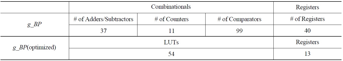
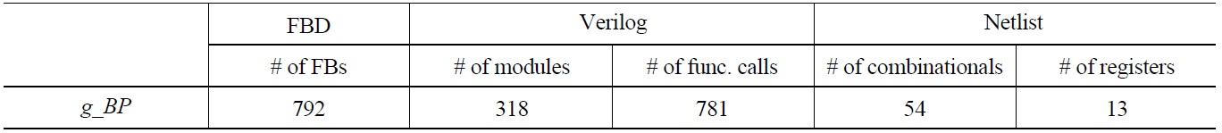
    Table1 summarizes features of the FBD programs, translated from the formal requirements specification by 'NuSCRtoFBD,' as shown in Fig.8 The actual starting point of the case study, the NuSCR formal requirements specification [19], is beyond the scope of this paper and a detailed description of its features can be found in [19]. The formal requirements specification includes 6 shutdown logics in the KNICS RPS BP. These are all translated into an FBD program 'g_BP' with 792 function blocks in 4 levels of depth. Since an FBD is a sequential program, the FBD program of 792 function blocks sequentially executes all function blocks once every execution cycle. Complexity of the translated FBDs varies according to the category of shutdown logics. For example, the digital logic is translated into the simplest FBD program with no timer function block, while the manual reset logic into the longest one with a number of EOs, IOs and timer function blocks. EO means external outputs while IO does intermediate/internal outputs used for storing information to use later. Many-IOs indicate high-complexity of the shutdown logic, indirectly.

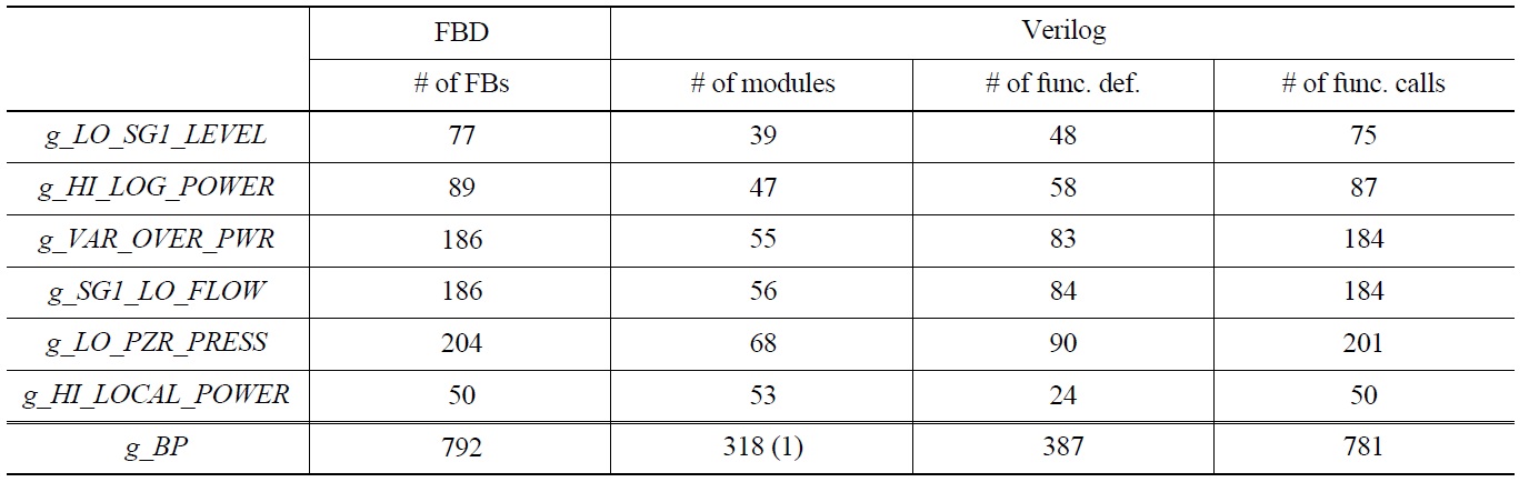
    Table 2 explains the features of the Verilog program translated from the FBD, which is summarized in Table 1 by the new 'FBDtoVerilog.' The FBD program of 792 function blocks is translated into a Verilog program 'g_BP' of 8,258 lines. It calls the 318 Verilog modules sequentially according to their execution orders, while all modules call Verilog functions 781 times. A Verilog function corresponds to a function block in FBD, such as ADD_INT or SEL. A Verilog module also corresponds to a component FBD. Since all Verilog functions used in a Verilog module should be defined within the definition of the Verilog module, the same Verilog functions are redundantly defined several times in different modules.

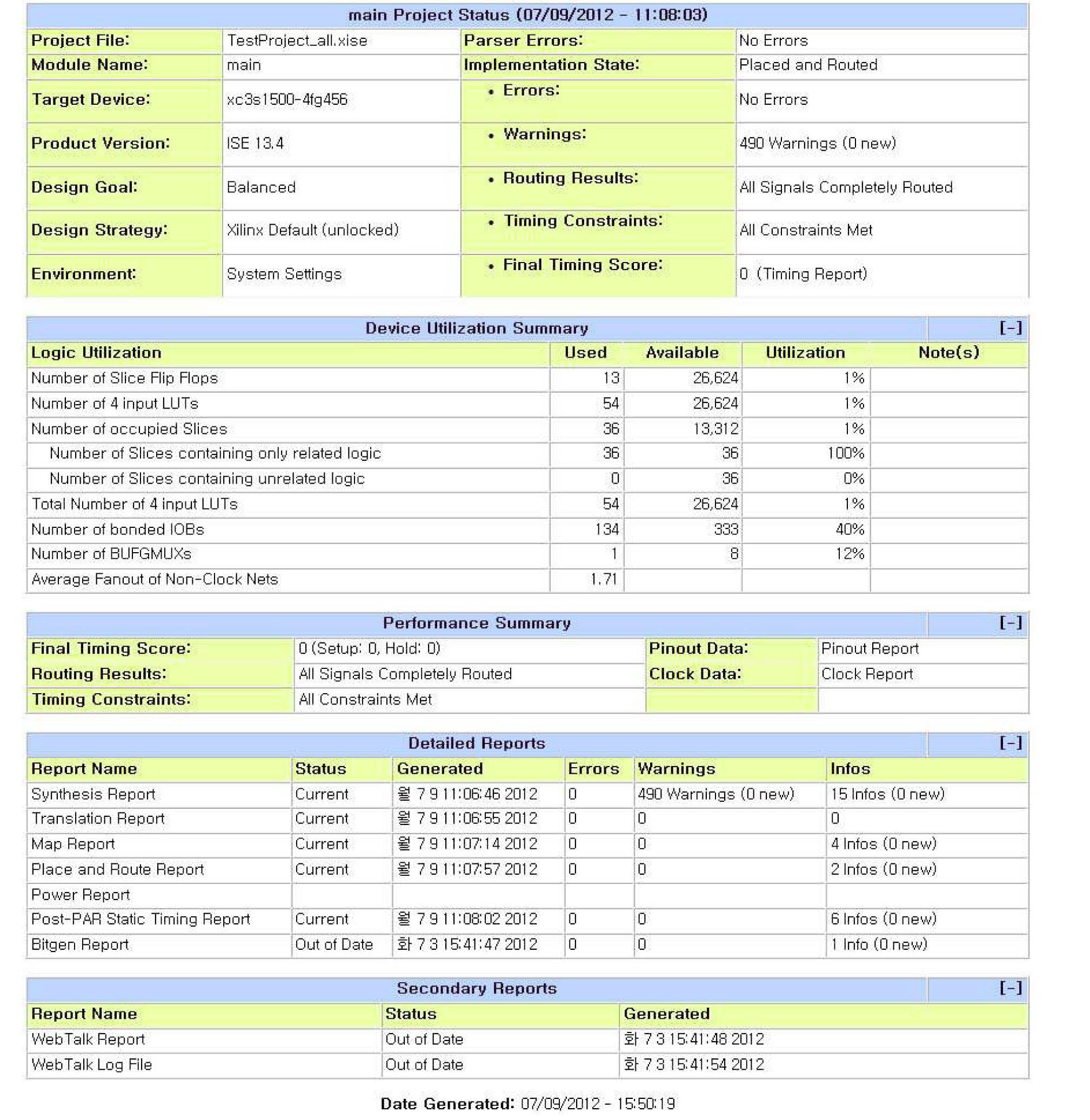
    The Verilog program analyzed in Table 2 is the starting point of the FPGA-based development. Two FPGA synthesis tools, Xilinx ISE Design Suite' and 'Altera Quartus II,' read the Verilog program and synthesized FPGA programs (i.e., a set of netlists and registers). Table 3 is the result of the FPGA synthesis by using 'Xilinx ISE Design Suite.' It produced 147 combinationals and 40 registers, but optimization step produced 54 LUTs and 13 registers. Fig. 9 is a report summarizing the whole FPGA synthesis, produced by the tool.

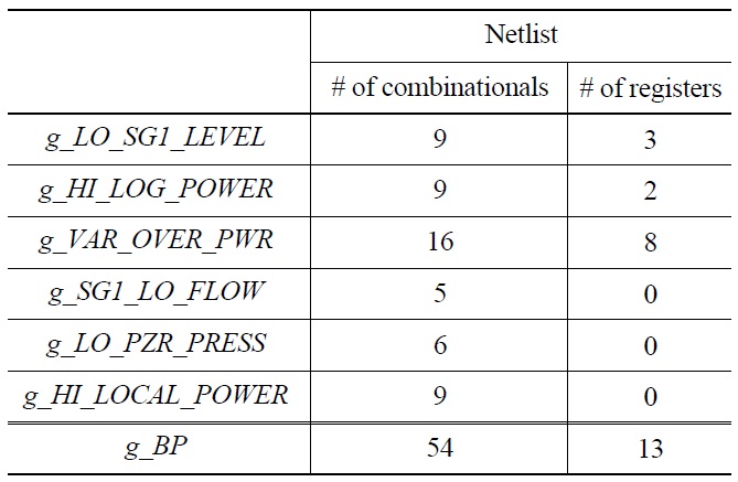
    Table 4 is the synthesis result of the'Altera Quartus II' synthesis tool, after the optimization step. Compared with the 'Xilinx ISE Design Suite,' it provides more detailed numbers of combinationals and registers for individual modules. They both, however, use the same number of netlists (i.e., combinationals and registers). This paper used the 'Xilinx ISE Design Suite' to download the configuration into an FPGA.

    Table 5 summarizes important features of all outputs, from the PLC design phase to the FPGA implementation. It is not an exact analysis, but it is obvious that the FPGA implementation consists of fewer elements than the more abstract ones such as FBD and Verilog programs.

       5.3 Further Consideration

    We are now considering the following issues carefully to apply the proposed RPS development process to an actual RPS development:

    Radiation Resistance of FPGA : Recent research [44,45] has reported that a specific type of FPGA using

    [Table 2.] A Feature of the Verilog Program Translated by the New 'FBDtoVerilog'

    label

    A Feature of the Verilog Program Translated by the New 'FBDtoVerilog'

    [Table 3.] A Feature of the FPGA Synthesized by 'Xilinx ISE Design Suite'

    label

    A Feature of the FPGA Synthesized by 'Xilinx ISE Design Suite'

    SRAM is vulnerable to radiation. It is obvious that this type of FPGA is inappropriate in the implementation of RPSs. The FPGA of 'Xilinx,' which the case study

    used, is the type vulnerable to radiation, and we need to find an appropriate FPGA for RPS.

    VHDL Generator : 'Mentor Graphics's HDL Designer Series' [29] is an example of VHDL generator, widely used to implement FPGA and ASIC mechanically. It models system behavior with various tools, such as FSM (Finite State Machine), flow-chart and block diagrams, and mechanically generates a behaviorallyequivalent VHDL program. It corresponds to 'FBDto Verilog' in our approach. However, it is the tool of hardware designers not of software engineers.

    RTL Optimization : The optimization step of FPGA synthesis tools produced several warnings worth looking into carefully. For example, it warned that some wire variables in the Verilog program were not used and it deleted them, even if they were all used correctly. We need to analyze the optimization process and potential threats to the functional correctness of the RPS BP.

    Functional Safety of FBDtoVerilog : Functional safety and correctness of the 'FBDtoVerilog' translator should be demonstrated thoroughly in various ways. Whereas it was a supporting CASE tool for formal verification using SMV, VIS and HW-CBMC, it is now a development tool bridging PLC-based and FPGA-based development. More rigorous demonstration of functional safety and correctness is highly required.

    Functional Safety of FPGA Synthesis Tools : Functional safety and correctness of FPGA synthesis tools (e.g., 'Xilinx ISE Design Suite' and 'Altera Quartus II') is also one of key issues in overcoming the wide-spread commercialization of the FPGA-based RPS development.

    [Table 4.] A Feature of the FPGA Synthesized by 'Altera Quartus II'

    label

    A Feature of the FPGA Synthesized by 'Altera Quartus II'

    [Table 5.] Important Features of the FBD, Verilog and FPGA Program in a Sequence

    label

    Important Features of the FBD, Verilog and FPGA Program in a Sequence

    Highly Integrated RPS Components : As depicted in Fig. 3, an RPS is structured with many components such as BPs and CPs, which were implemented in an individual PLC with a network-based communication. We are now going to implement a channel (consisting of 2 BPs, 2 CPs and communication networks) in an FPGA. Communication between components in a channel and with ones in other channels should be designed in an FPGA. I/O is also an issue to be resolved, since the PLC provides with convenient ways to interface with I/O devices.

    6. RELATED WORK

    There are several approaches to implement RPSs with Programmable logic device (PLD) such as an FPGA. PLD has been widely used by many industries such as aviation, space, chemical, military and other highly safety-critical industries. Nuclear industry has also been interested in the approach and technology [46,47]. The IAEA workshop on 'Application of Field-Programmable Gate Array in Nuclear Power Plants' was held for 3 years from 2008, and attempts to implement I&C systems in NPPs with FPGA were presented as follows.

    Radiy [48] in Ukraine has developed a few FPGAbased safety-critical digital I&C systems [13,49]. CS Innovation [50] in USA provides an FPGA development platform - 'ALS' (Advanced Logic System) for implementing safety-critical I&C systems. Wolf Creek Nuclear Operating Corporation used it to modify a main steam and feed water isolation system [51]. Several researches and prototypes also have been under development by KAERI (Korea Atomic Energy Research Institute) in Korea [11,12].

    7 . CONCLUSION AND FUTURE WORK

    This paper proposes an RPS software development process with a platform change from PLC to FPGA, while retaining all outputs from the established development. The new 'FBDtoVerilog' translator transforms FBD designs of the PLC-based software development into a behaviorally-equivalent Verilog program which is a starting point of typical FPGA-based development. In order to confirm the effectiveness of the proposed approach, we performed a case study with an example of a preliminary prototype version of the KNICS RPS BP, and demonstrated a seamless transition from the PLCbased development to the FPGA-based one.

    This paper used an example of FBD programs, which were mechanically translated from a formal requirements specification and have different features from the ones programmed manually. We are planning to apply the proposed development process to an actual FBD program designed by FBD programmers. Rigorous demonstration of functional correctness and safety of 'FBDtoVerilog' and the FPGA synthesis tools is also an ongoing research issue to resolve for the wide use of the FPGA-based RPSs. We are planning to apply to 'FBDtoVerilog' the 'safety/dependablilty case' approach [52] as well as compiler verification techniques [53]. Our recent survey on the translator verification [54] suggests that the credible compilation [55] and translation validation [56] techniques would be good candidates for the verification. We are currently focusing on analyzing the effect of the RTL optimization by FPGA synthesis tools.

참고문헌
  • 1. (1993) International standard for programmable controllers: Programming languages, part 3 google
  • 2. She J. (2012) "Investigation on the Benefits of Safety Margin Improvement in CANDU Nuclear Power Plant Using an FPGA-based Shutdown System" google
  • 3. (2009) Survey of the CPLD/FPGA Technology for Application to NPP Digital I&C System, Tech. Rep. google
  • 4. Programmable logic controller google
  • 5. (2010) "IEEE 7-4.3.2: Standard Criteria for Digital Computers in Safety Systems of Nuclear Power Generating Stations" google
  • 6. (1996) "Generic Requirements Specification for Qualifying a Commercially Available PLC for Safety-Related Application in NPPs" google
  • 7. Stephen Brown J. R. (1996) FPGA and CPLD Architectures: A Tutorial, vol. 13 google
  • 8. Field-programmable gate array google
  • 9. Korea nuclear instrumentation and control system r&d center google
  • 10. Yoo J., Cha S., Jee E. (2009) "Verification of PLC Programs written in FBD with VIS" [Nuclear Engineering and Technology] Vol.41 P.79-90 google cross ref
  • 11. Choi J. G. (2008) "Experiences of an FPGA-based Safety-Critical System Development for an Application to Nuclear Power Plants in Korea" [1st Workshop on the Applications of Field-Programmable Gate Arrays in Nuclear Power Plants] google
  • 12. Lee J.-K. (2008) "Design and Verification Process for Developing the FPGA-based Firmware for NPPs" [1st Workshop on the Applications of Field-Programmable Gate Arrays in Nuclear Power Plants] google
  • 13. Siora A. (2008) "Experience of RPC "Radiy" in Designing, Manufacturing and Implementation of FPGA based NPP I&C Systems" [1st Workshop on the Applications of Field-Programmable Gate Arrays in Nuclear Power Plants] google
  • 14. (2006) "Software Design Specification for Reactor Protection System" google
  • 15. Mishra S., Kushwaha D., Misra A. (2012) "Hybrid Reliable Load Balancing with Mosix as Middleware and its Formal Verification using Process Algebra" [Future Generation Computer System] Vol.28 P.1272-1282 google cross ref
  • 16. Heitmeyer C. L., Jeffords R. D., Labaw B. G. (1996) "Automated Consistency Checking of Requirements Specifications" [IEEE Transactions on Software Engineering] Vol.5 P.231-261 google
  • 17. Yoo J., Kim T., Cha S., Lee J.-S., Son H. S. (2005) "A Formal Software Requirements Specification Method for Digital Nuclear Plants Protection Systems" [Journal of Systems and Software] Vol.74 P.73-83 google
  • 18. Yoo J., Jee E., Cha S. (2009) "Formal Modeling and Verification of Safety-Critical Software" [IEEE Software] Vol.26 P.42-49 google cross ref
  • 19. (2003) "SRS for Reactor Protection System" google
  • 20. Yoo J., Cha S., Kim C. H., Song D. Y. (2005) "Synthesis of FBDbased PLC Design from NuSCR Formal Specification" [Reliability Engineering and System Safety] Vol.87 P.287-294 google cross ref
  • 21. (2003) "TMS320C55x Optimizing C/C Compiler Users Guide" google
  • 22. (1996) "Space, Engineering System of Teleperm XS PLC" google
  • 23. (1998) "Teleperm XS, Brief Description" google
  • 24. Richter S., Wittig J. (2003) "Verification and Validation Process for Safety I&C Systems" [Nuclear Plant Journal] P.36-40 google
  • 25. (1997) "Reverse Engineering Tool for FBD Programming of Teleperm XS PLC, Tech. Rep. google
  • 26. Safety software suite, TriStation 1131 (TS1131) google
  • 27. Cho S., Koo K., You B., Kim T.-W., Shim T., Lee J. S. (2007) "Development of the Loader Software for PLC programming" [Conference of the the Institute of Electronics Engineers of Korea] Vol.30 P.959-960 google
  • 28. Nuclear power in south korea google
  • 29. (2008) "HDL Designer Series User Manual" google
  • 30. Xilinx ise design suite google
  • 31. Altera quartus ii google
  • 32. Yoo J., Lee J.-H., Jeong S., Cha S. (2011) "FBDtoVerilog: A Vendor-Independent Translation from FBDs into Verilog Programs" [The 23rd international Conference on Software Engineering and Knowledge Engineering (SEKE 2011)] P.48-51 google
  • 33. Jee E., Jeon S., Cha S., Koh K., Yoo J., Park G., Seong P. (2010) "FBDVerifier: Interactive and Visual Analysis of Counterexample in Formal Verification of Function Block Diagram" [Journal of Research and Practice in Information Technology] Vol.42 P.255-272 google
  • 34. Lee D.-A., Yoo J., Lee J.-S. (2011) "Equivalence Checking between Function Block Diagrams and C Programs using HW-CBMC" [The 30th International Conference on Computer Safety, Reliability and Security (SAFECOMP 2011)] P.397-408 google
  • 35. McMillan K. L. (1993) Symbolic Model Checking google
  • 36. Clarke E. M., Grumberg O., Peled D. A. (1999) Model Checking google
  • 37. Synchronous verilog google
  • 38. Brayton R. K., Hachtel G. D., Sangiovanni-Vincentelli A., Somenzi F., Aziz A., Cheng S.-T., Edwards S. A., Khatri S. P., Kukimoto Y., Pardo A., Qadeer S., Ranjan R. K., Sarwary S., Shiple T. R., Swamy G., Villa T. (1996) "VIS: A System for Verification and Synthesis" [The 8th International Conference on Computer Aided Verification (CAV '96)] P.428-432 google
  • 39. Plcopen for efficiency in automation google
  • 40. Clarke E. M., Kroening D. (2003) "Hardware Verification using ANSI-C Programs as a Reference" [Proceedings of the 2003 Asia and South Pacific Design Automation Conference] P.308-311 google
  • 41. Clarke E. M., Emerson E. A., Sistla A. P. (1986) "Automatic Verification of Finite-State Concurrent Systems using Temporal Logic Specifications" [ACM Trans. Programming Languages and Systems] Vol.8 P.244-263 google cross ref
  • 42. Lee J.-H., Yoo J. (2012) "NuDE: Development Environment for Safety-Critical Software of Nuclear Power Plant" [Transactions of the Korean Nuclear Society Spring Meeting 2012] P.114-1155 google
  • 43. Lee D.-A., Yoo J. (2011) "pSET2TC6: A Translation Tool to Standardize the Output Format of pSET" [KIISE Spring Meeting 2011] P.105-107 google
  • 44. Dangla D. (2008) "FPGA for Space Applications" [1st Workshop on the Applications of Field-Programmable Gate Arrays in Nuclear Power Plants] google
  • 45. Wang J. (2003) "Radiations Effects in FPGAs" [9th Workshop on Electronics for LHC Experiments] google
  • 46. (2010) Review guidelines for field-programmable gate arrays in nuclear power plants safety systems google
  • 47. (2009) "Guidelines on the Use of Field Programmable Gate Arrays in Nuclear Power Plant I*8C Systems" google
  • 48. Radiy google
  • 49. Siora A. (2008) "FPGA Properties and Safety Assurance of NPP I&C Systems" [1st Workshop on the Applications of Field-Programmable Gate Arrays in Nuclear Power Plants] google
  • 50. CS Innovation google
  • 51. Dittman B. F. (2009) "Regulatory Experience with FPGA-based Digital I&C Review" [2nd Workshop on the Applications of Field-Programmable Gate Arrays in Nuclear Power Plants] google
  • 52. Jackson D. (2009) "A Direct Path to Dependable Software" [Communications of the ACM] Vol.52 P.78-88 google cross ref
  • 53. Dave M. A. (2003) "Compiler Verification: A Bibliography" [ACM SIGSOFT Software Engineering Notes] Vol.28 P.2-2 google
  • 54. Lee E.-S., Lee D.-A., Yoo J. (2013) "A Survey on the Verification Methods for Translator" [Proceeding of Korea Conference on Software Engineering (KCSE 2013)] google
  • 55. Rinard M., Marinov D. (1999) "Credible Compilation with Pointers" [Proceedings of FLoC Workshop on Run-Time Result Verification] google
  • 56. Pnueli A., Siegel M., Singerman E. (1998) "Translation Validation", Tools and Algorithms for the Construction and Analysis of Systems P.151-166 google
  • 57. 2005 Functional safety of electrical/electronic/programmable electronic safety-related systems, IEC 61508 google
OAK XML 통계
이미지 / 테이블
  • [ Fig. 1. ]  An FBD for th_X_Pretrip Logic in KNICS RPS BP
    An FBD for th_X_Pretrip Logic in KNICS RPS BP
  • [ Fig. 2. ]  A Verilog Program Translated from the FBD in Fig.1
    A Verilog Program Translated from the FBD in Fig.1
  • [ Fig. 3. ]  A Simplified Architecture of the KNICS RPS [15]
    A Simplified Architecture of the KNICS RPS [15]
  • [ Fig. 4. ]  A Typical RPS Software Development Process using PLCs
    A Typical RPS Software Development Process using PLCs
  • [ Fig. 5. ]  An RPS Software Development Process using FPGA
    An RPS Software Development Process using FPGA
  • [ Fig. 6. ]  The Proposed RPS Software Development Process with Platform Change
    The Proposed RPS Software Development Process with Platform Change
  • [ Fig. 7. ]  A Screen-dump of the New 'FBDtoVerilog' (An Eclipse Plug-in)
    A Screen-dump of the New 'FBDtoVerilog' (An Eclipse Plug-in)
  • [ Fig. 8. ]  An Overview of the Case Study Performed
    An Overview of the Case Study Performed
  • [ Table 1. ]  A Feature of the FBD Program used
    A Feature of the FBD Program used
  • [ Table 2. ]  A Feature of the Verilog Program Translated by the New 'FBDtoVerilog'
    A Feature of the Verilog Program Translated by the New 'FBDtoVerilog'
  • [ Table 3. ]  A Feature of the FPGA Synthesized by 'Xilinx ISE Design Suite'
    A Feature of the FPGA Synthesized by 'Xilinx ISE Design Suite'
  • [ Fig. 9. ]  A synthesis Summary Report from 'Xilinx ISE Design Suite'
    A synthesis Summary Report from 'Xilinx ISE Design Suite'
  • [ Table 4. ]  A Feature of the FPGA Synthesized by 'Altera Quartus II'
    A Feature of the FPGA Synthesized by 'Altera Quartus II'
  • [ Table 5. ]  Important Features of the FBD, Verilog and FPGA Program in a Sequence
    Important Features of the FBD, Verilog and FPGA Program in a Sequence
(우)06579 서울시 서초구 반포대로 201(반포동)
Tel. 02-537-6389 | Fax. 02-590-0571 | 문의 : oak2014@korea.kr
Copyright(c) National Library of Korea. All rights reserved.