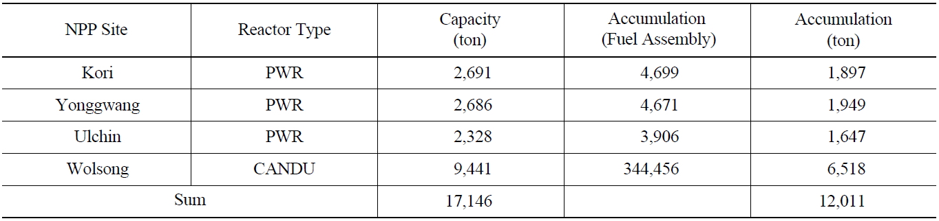
In Korea, seventeen PWRs (Pressurized Water Reactors) and four CANDU reactors are in operation, as of March 2012. Seven reactors are under construction. Among them, one more PWR is scheduled to start operation shortly. The amount of spent fuel remarkably increases as the number of nuclear reactors increases. Nowadays, around 300 MtU of PWR spent fuel and 400 MtU of CANDU spent fuel are discharged annually. The current amount of spent fuel stored at each nuclear power plant site is given in Table 1. As shown in Table 1, the total amount of spent fuel in Korea is more than 11,000 MtU. According to the current projection, it is expected that more than 60,000 MtU of spent fuel will be generated from 40 nuclear reactors by the end of 2089.
In 2006, KAERI proposed a conceptual design of a geological disposal system (called KRS, Korean Reference disposal System for spent fuels) for PWR and CANDU spent fuel, as a product of a 4-year research project from 2003 to 2006 [1]. KRS was designed for the direct disposal of spent fuel, similar to that of the Swedish KBS-3V concept [2]. The design was made using representative data on granite in Korea. The major result of the research was that it was feasible to construct a direct disposal system for 20,000 MtU of PWR spent fuel and 16,000 MtU of CANDU spent fuel in the Korean peninsula. At the start of the project, KAERI understood the necessity of an underground research facility to improve the research technology and collect geological data, and therefore constructed a research tunnel called KURT (KAERI Underground Research Tunnel) [3].
Since no decision was made for the CANDU spent fuel, KAERI improved the disposal density of KRS by introducing new concepts for a disposal canister. Also, the authors tried to apply a new technique, called a cold spray coating, to manufacture a thinner copper outer shell of the disposal canister to remarkably save the amount of copper [4]. Geological data had been collected from KURT since the beginning of operation, which were used for the design of a disposal system and a performance assessment instead of the representative data.
KAERI and MEST launched a project to develop an advanced fuel cycle, based on the pyroprocessing of PWR spent fuel, to reduce the amount of HLW and reuse the valuable fissile material. Thus, KAERI has developed a geological disposal system for high-level waste from the pyroprocessing of PWR spent fuel since 2007. In this paper, the geological disposal systems developed so far are briefly outlined. The amount and characteristics of spent fuel and HLW, four kinds of disposal canisters, the characteristics of a buffer with Korean domestic Ca-bentonite, and the results of a thermal design of the deposition holes and disposal tunnels are described.
[Table 1.] Amount of Spent Fuels at the Sites (as of end of 2011).

Amount of Spent Fuels at the Sites (as of end of 2011).
[Table 2.] Amount of Spent Fuels used for the Design of KRS [1]
Amount of Spent Fuels used for the Design of KRS [1]
2. DIRECT DISPOSAL OF PWR AND CANDU SPENT FUEL
KAERI was asked to develop a geological disposal system for PWR and CANDU spent fuel, to determine whether it was feasible to construct a geological disposal system in the Korean peninsula, through the Nuclear Research and Development Program of the Korea Ministry of Science and Technology. KAERI carried out a conceptual design of a geological disposal system, called KRS, from 2003 to 2006. In this paper, the major characteristics of the KRS are briefly outlined.
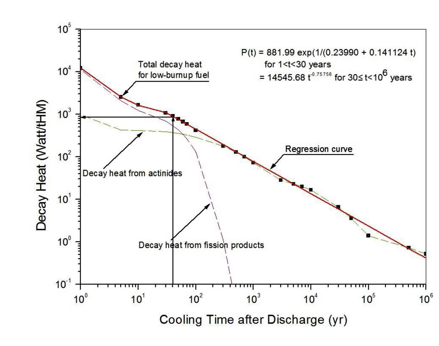
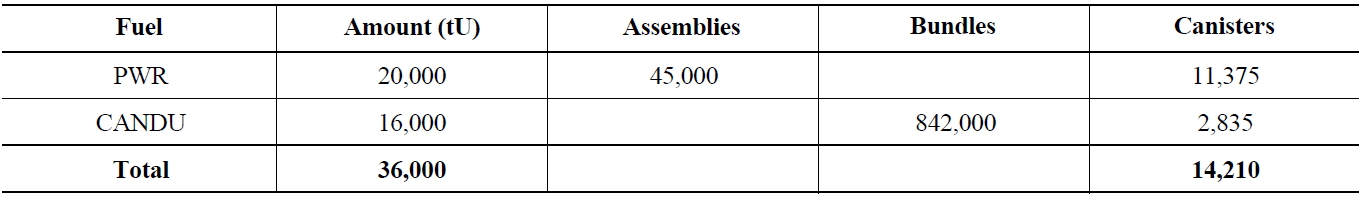
The KRS was designed to accommodate the spent fuels from the 4 CANDU reactors at the Wolsong site, and a total of 16 PWR reactors at the Kori, Yonggwang, and Ulchin. The total amount of spent nuclear fuel expected from twenty reactors is presented in Table 2. If four PWR spent fuel assemblies are put in one disposal canister, around 11,000 disposal canisters are needed to accommodate 20,000 MtU of PWR spent fuel. Similarly, 297 CANDU spent fuel bundles in a disposal canister means around 2,800 disposal canisters for all CANDU spent fuel. The reference spent fuel is characterized for the design of the KRS, as given in Table 3 [5]. The decay heat from the reference PWR spent fuel (Table 3) is calculated using the ORIGEN-ARP program [6], and the results are shown in Fig. 1 [7]. As shown in Fig. 1, the decay heat from the PWR spent fuel was around 890 W/tHM at 40 years after the discharge, which was equivalent to a 1.6 kW/canister. The decay heat for a CANDU spent fuel canister was around 760 W/canister.
Since a repository site had never been discussed in Korea, the design of the KRS was based on the representative geological data on granite, which is a candidate rock for a disposal system. In this paper, we assume that the repository will be constructed into a granite rock mass. A geo-thermal gradient of 30℃/km is used as a basis for the design [7].
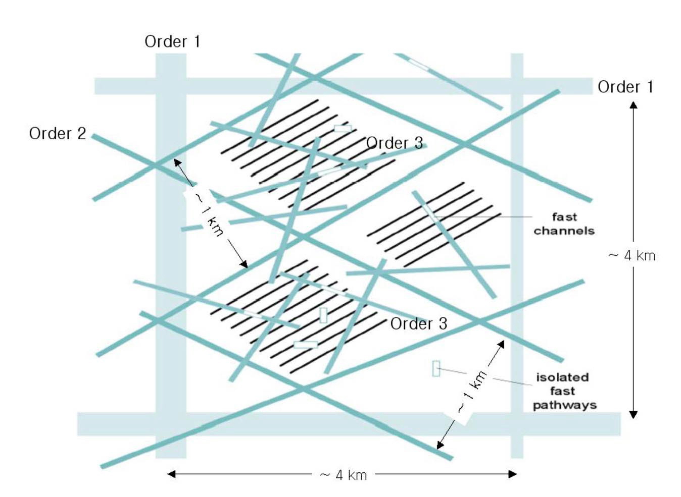
The fracture zones are divided into four main classes (see Table 4 and Fig. 2) [1]. The repository is designed
[Table 3.] Characteristics of the Reference Spent Fuel for KRS [5]
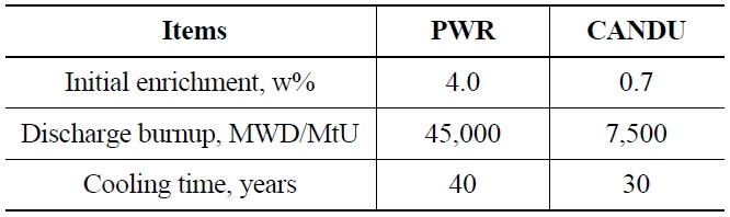
Characteristics of the Reference Spent Fuel for KRS [5]
[Table 4.] Classification of the Fracture Zones [1, 7]
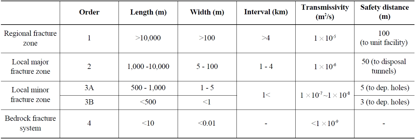
Classification of the Fracture Zones [1, 7]
so that the whole repository fits inside an intact bedrock block, bordered by regional fracture zones (order 1). The disposal tunnel panels should be placed so that they have a 50 m safety distance to the local major fracture zones (order 2). The disposal tunnels can penetrate the local fracture zones (order 3), but there should be certain safety distances to the nearest disposal holes. In addition, all potential fast radionuclide pathways will be isolated from the tunnel with plug structures.
2.3 Disposal Canisters and Buffer
The main function of the canister is the containment of the radionuclides during the specified period. The canisters consist of two parts. One is an outer shell for corrosion resistance, and the other is an insert for mechanical strength. This kind of canister was introduced in countries such as Sweden and Finland. In Table 5, the design requirements for the disposal canisters in KRS are compared with those of Finland [8].
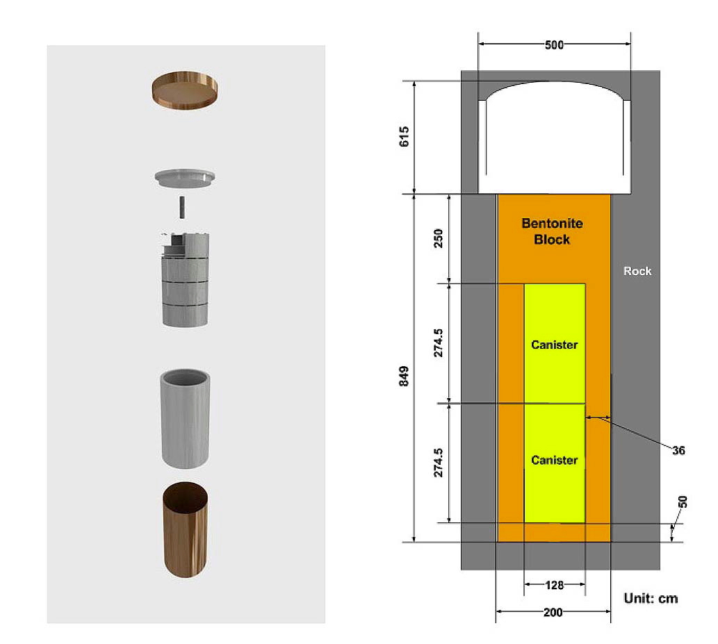
Four kinds of disposal canisters for high-level radioactive wastes were designed by the authors [7]. Nodular cast iron is selected as the material for the insert, and copper as the outer shell material. The thickness of the copper outer shell is 5 cm. A disposal canister called KDC-1 is selected for the disposal of PWR spent fuel [9]. A preconceptual design of the KRS is based on KDC-1, which contains four PWR spent fuel assemblies. The canister size is determined mainly by the diameter of the insert, and the diameter of the insert is determined through a structural analysis [10]. The insert has to be designed to withstand the hydrostatic pressure and a swelling pressure from the bentonite buffer. Similarly, a disposal canister for the CANDU spent fuel, KDC-CANDU, was designed. A KDC-CANDU canister contains 297 CANDU spent fuel bundles (Fig. 3).
In a geological disposal system, the major function of a buffer is to protect the disposal canister under the expected geological conditions. Generally, the material for a buffer is selected to prevent groundwater from flowing through the buffer, which means a very low hydraulic conductivity. Domestic Korean Ca-bentonite has been characterized as a candidate buffer material for the KRS. The design requirements set for the design of a KRS buffer are given in Table 6 [7]. A dry density of 1.6 g/cm3 gives a thermal conductivity of around 1.0 W/m℃. The thickness of the buffer is designed to be 50 cm to minimize the release rates of the radionuclides [11]. The size of the buffer for the PWR and CANDU spent fuel is shown in Fig. 4.
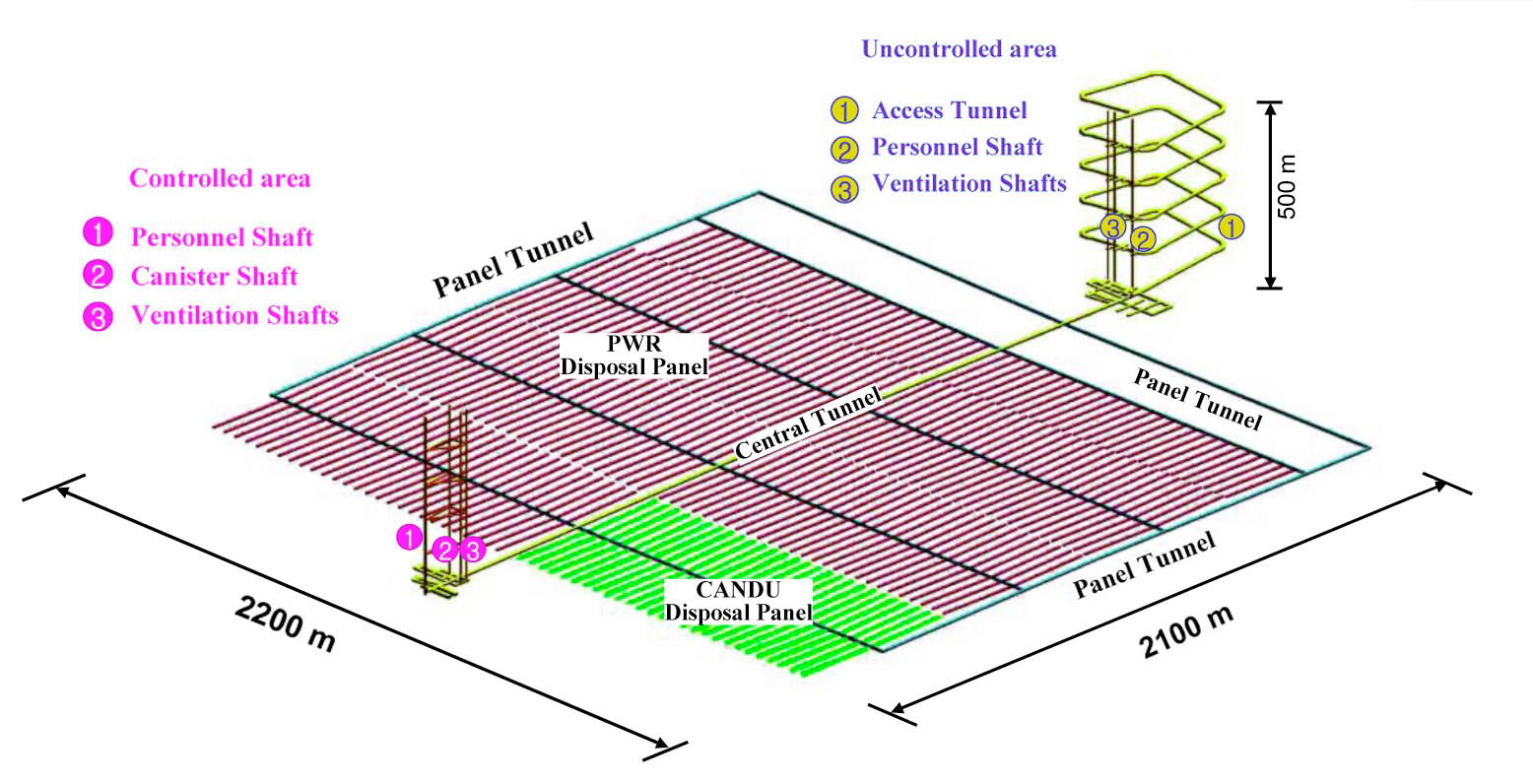
2.4 Layout of a Disposal System
The depth of the repository is set to be 500 m below the surface. The repository consists of the following three sections: a disposal area, technical rooms in the controlled area, and technical rooms in the uncontrolled area. The disposal area consists of disposal tunnels, panel tunnels, and a central tunnel, as shown in Fig. 5. The number of
[Table 5.] Design Requirements for a Disposal Canister
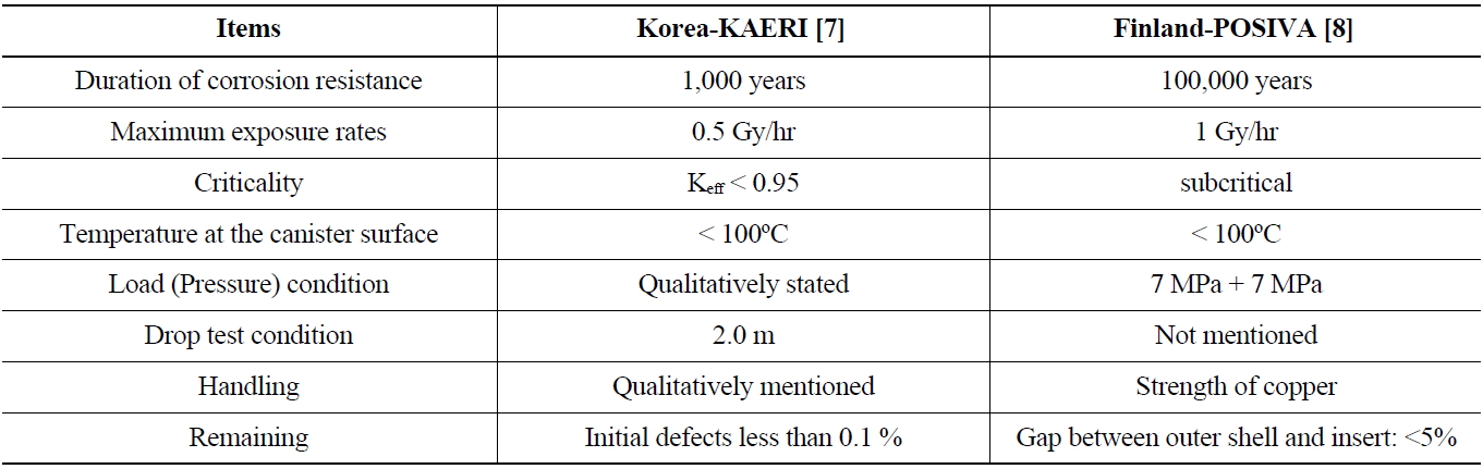
Design Requirements for a Disposal Canister
deposition holes in a disposal tunnel is determined to be 37 holes for PWR spent fuel and 55 holes for CANDU spent fuel [1]. The number and length of the disposal
[Table 6.] Design Requirements for a Buffer [7]
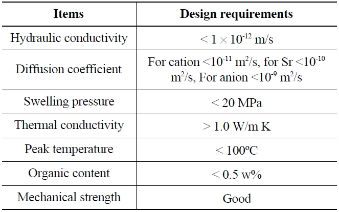
Design Requirements for a Buffer [7]
tunnels are given in Table 7. The distance between the deposition holes was determined through a thermal analysis [12]. The peak temperature in a buffer did not exceed 100℃. For the disposal of PWR spent fuel, the spacing of 40 m for tunnels and a distance of 6 m between deposition holes showed a peak temperature of 98.6℃. The thermal conductivity of a buffer with a dry density of 1.6 g/cm3 was 1.0 W/m℃ [7].
3. IMPROVEMENT OF A CANDU SPENT FUEL DISPOSAL SYSTEM
3.1 New CANDU Spent Fuel Disposal Canister
Since the reuse of CANDU spent fuels had not been considered in Korea, direct disposal of them was still a promising option for long-term management. According to the KRS design, the disposal density of CANDU spent fuels was around 297 bundles in 160 m2, which was
equivalent to around 0.035 MtU/m2. The disposal density was enhanced by improving the CANDU disposal canister.
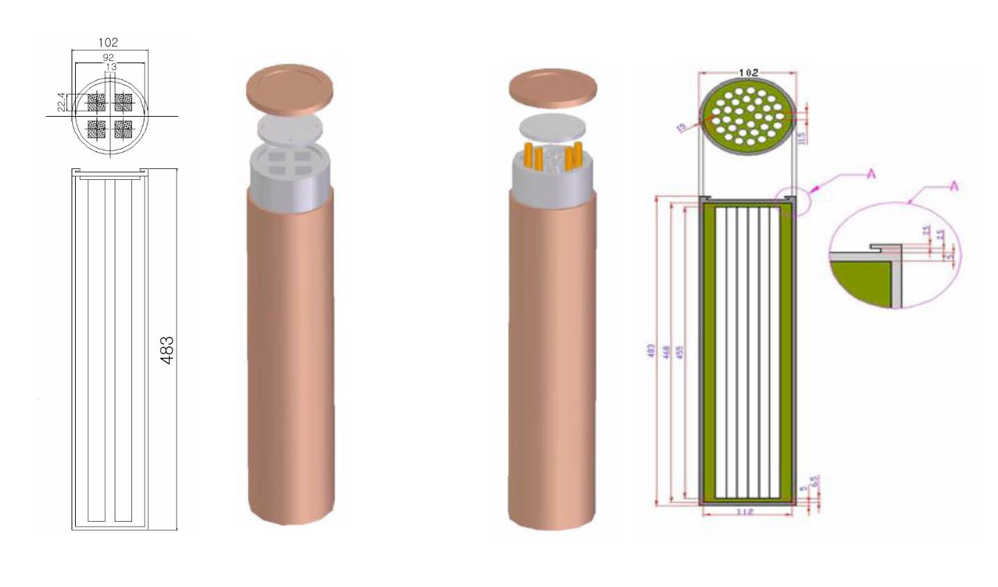
The thermal analysis showed that the peak temperature occurred at the middle of the canister, due to the symmetry. Thus, we propose a new canister, called A-KDC-CANDU, which contains four CANDU baskets (Fig. 6) [13]. One
[Table 7.] Number and Length of Disposal Tunnels [1, 7]
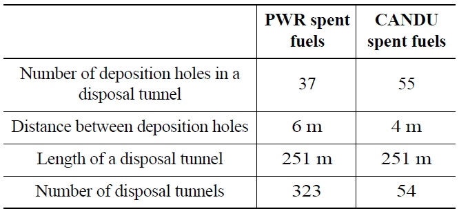
Number and Length of Disposal Tunnels [1, 7]
CANDU basket contains sixty CANDU spent fuel bundles. Thus, one A-KDC-CANDU canister contains 240 CANDU spent fuel bundles. Also, a new cold spray technique is introduced to fabricate the thinner copper outer shell [4,14]. With the cold spray technique, the thickness of the copper shell can be remarkably reduced from 5 cm to 1 cm. The specifications of the canisters are compared in Table 8 [13].
Whereas the geological data for the design of the KRS
[Table 8.] Comparison of Disposal Canisters [13]
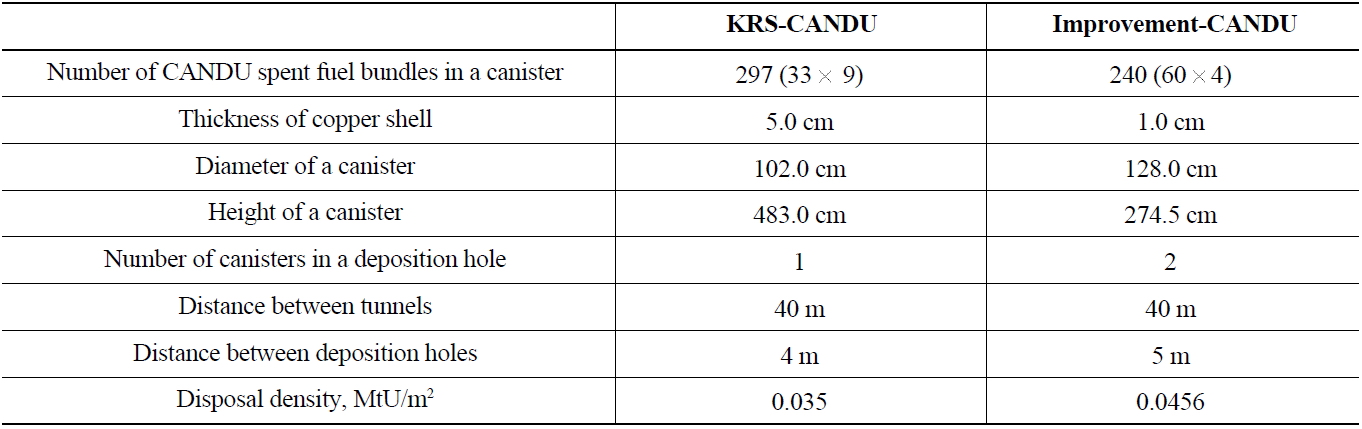
Comparison of Disposal Canisters [13]
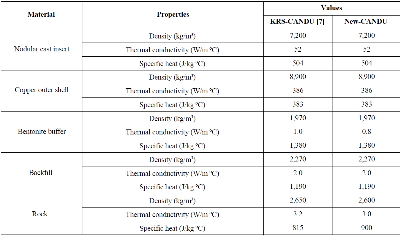
[Table 9.] Thermal Properties of Disposal System

Thermal Properties of Disposal System
was obtained mainly from the literature, the improvement is based on the geological data measured at KURT [3]. The thermal properties of granite are slightly changed, as shown in Table 9. Also, the thermal conductivity of the Ca-bentonite buffer changed a little from 1.0 W/m℃ to 0.8 W/m℃. The thickness of the buffer changed from 50 cm to 36 cm. As given in Table 8, the improvement increases the disposal density around 30 % (from 0.035 MtU/m2 to 0.0456 MtU/m2).
3.2 Thermal Analysis for a CANDU Spent Fuel Disposal System
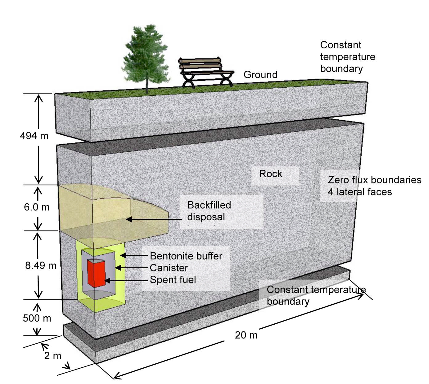
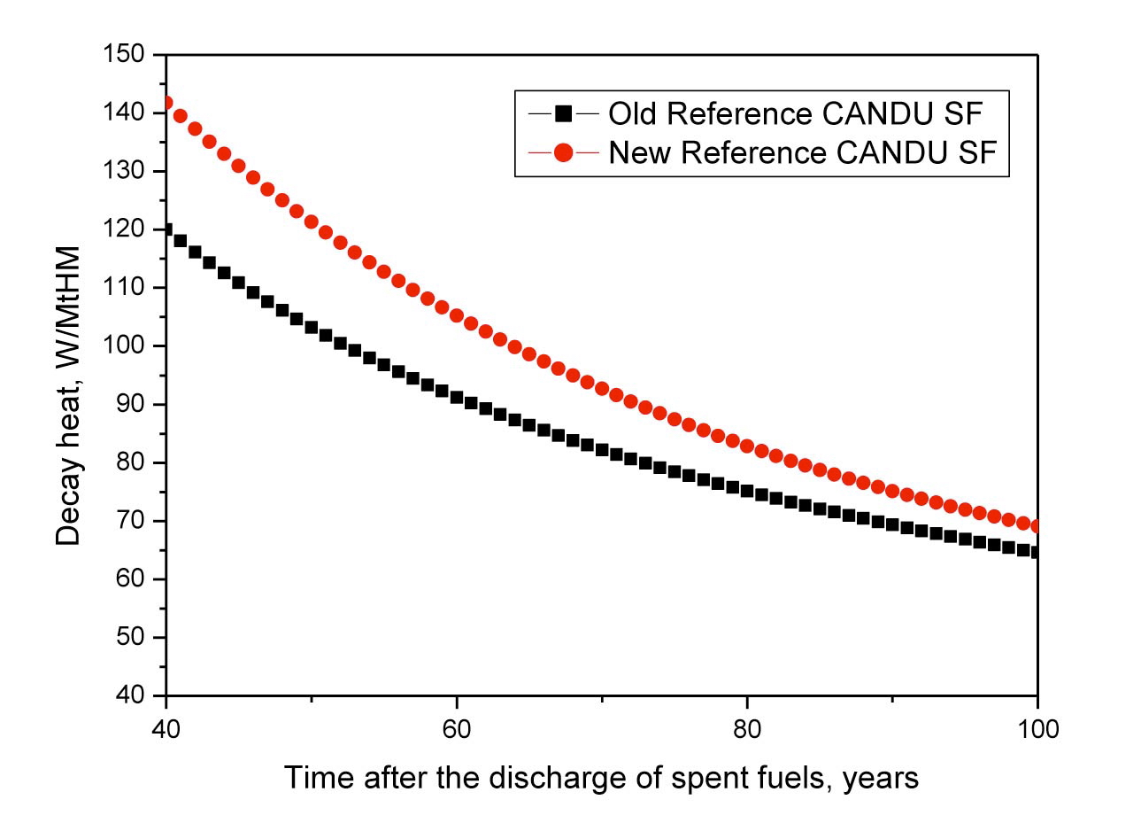
For the design of a disposal system with new canisters, a thermal analysis is carried out using the ABAQUS program [15]. The reference CANDU spent fuel is modified to conservatively assess the thermal performance. According to Cho et al. [16], the updated reference spent fuel showed a discharge burnup of 8,100 MWD/MtU. The decay heat from the old reference CANDU spent fuel and the new reference is compared in Fig.7. The thermal analysis is carried out at the unit-cell scale. Once the spent fuel is disposed of in a repository, the heat transfer in the crystalline rock and buffer is mainly through conduction. A schematic view of the calculation domain for a quarter of one canister, including the deposition hole and disposal tunnel, is given in Fig. 8 [14]. The disposal tunnel is
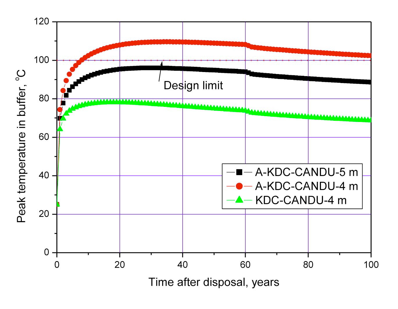
located at 500 m below the surface. The spacing between the disposal tunnels is 40 m, and the distance between the deposition holes is 4 m for KRS and 5 m for the new canister, respectively. For the thermal analysis, the bottom boundary is set at 500 m from the bottom of the deposition hole. Due to the symmetry of the disposal system, only a quarter of one deposition hole is modeled for the thermal analysis. That is, the heat transfer through the four lateral sides is neglected (zero heat flux). It is assumed that the temperatures of the ground surface and the bottom of the boundary remain constant at 10℃ and 40℃, respectively. The geo-thermal gradient of the site is 30℃/km based on the KURT measurements [17]. The results of the thermal analysis are shown in Fig. 9. The peak temperature for a distance of 4 m between the deposition holes exceeds the temperature design limit of 100℃.
4. DISPOSAL SYSTEM FOR HLW FROM THE PYROPROCESSING OF PWR SPENT FUEL
Pyroprocessing is a new recycling process for extracting reusable uranium and transuranium elements (TRU) from spent nuclear fuel [18]. The process uses molten salt, not an aqueous solution, for the reaction medium, to adhere to the nuclear non-proliferation treaty. Various nuclides are dissolved in molten salt, and are electrochemically extracted by a cathode electrode in consecutive order of their reduction potentials. The pyroprocessing consists of four main processes: de-cladding and voloxidation, electrolytic reduction, electro-refining, and electro-winning. Each process handles high radioactive materials and inevitably generates radioactive waste. Most uranium is recovered for reuse or is disposed of as low-level waste, and TRU, including plutonium, will be separated together and used as fuel material for fast reactors. Iodine and technetium will be separated during the voloxidation process, and are expected to be transmuted in the future. Cesium and strontium will be separated through the voloxidation and electrolytic reduction process, stored temporarily to decay, and then disposed of as low-level waste. A small amount of TRU and strontium will be generated from the electrowinning process and treated with a monazite ceramic, which is the only form of HLW from the pyro-processing of PWR spent fuel [18].
4.1 High-level Waste form and a Disposal Module
The characterization of the waste form should be carried out for the design of a geological disposal system. The waste characteristics strongly depend on the material
balance of the pyroprocess and the reference spent fuel. The source terms of HLW from the pyroprocess are analyzed using the A-SOURCE program [19]. In this paper, a storage canister and a disposal canister are designed, taking into account the mass and decay heat of the monazite ceramic waste.
It is anticipated that around 665 kg of monazite ceramic waste will be produced from the pyroprocess of 10 MtU of PWR spent fuel, as given in Table 10. In this paper, a disposal module means a unit system comprising waste storage canisters, disposal canisters, a buffer, a deposition hole, and a disposal tunnel. Considering the waste treatment process, the size and weight of the ceramic waste block is determined, as given in Table 11. Around 14 ceramic waste blocks are produced from the pyroprocess of 10 MtU of PWR spent fuel. If a waste block is fabricated, as
[Table 10.] Characteristics of High-level Wastes from Pyroprocessing of 10 MtU PWR Spent Fuels [20]
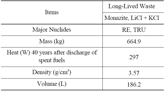
Characteristics of High-level Wastes from Pyroprocessing of 10 MtU PWR Spent Fuels [20]
[Table 11.] Specifications of the Waste Block and Storage Canister [20]
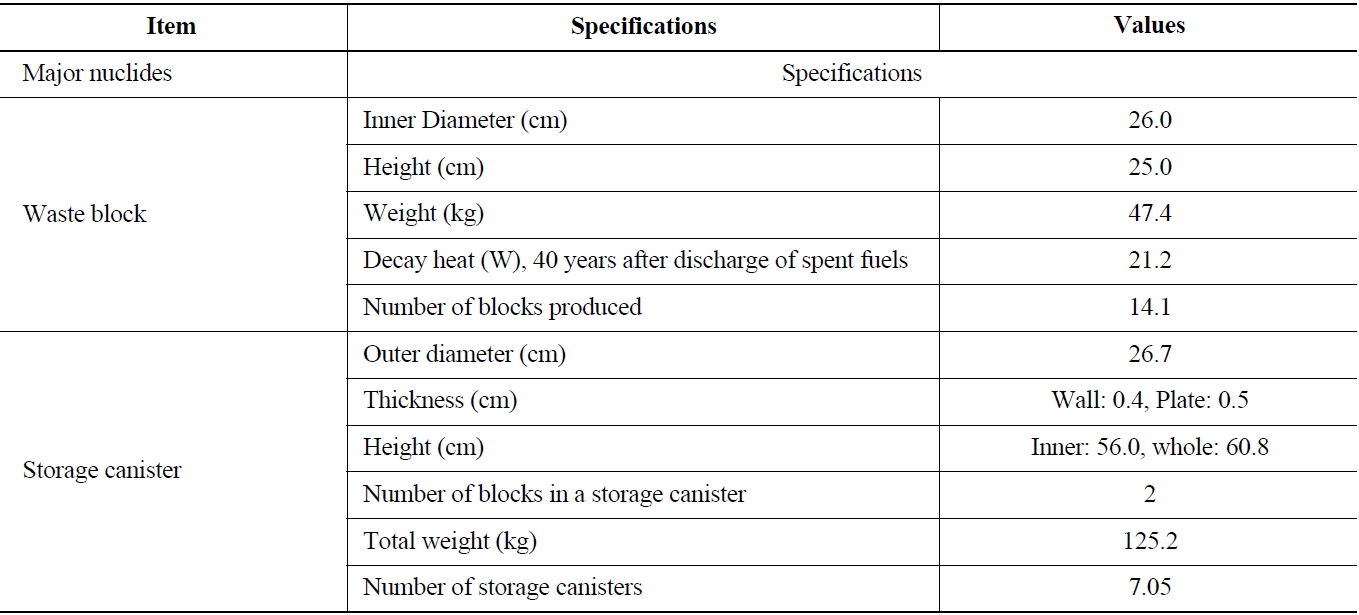
Specifications of the Waste Block and Storage Canister [20]
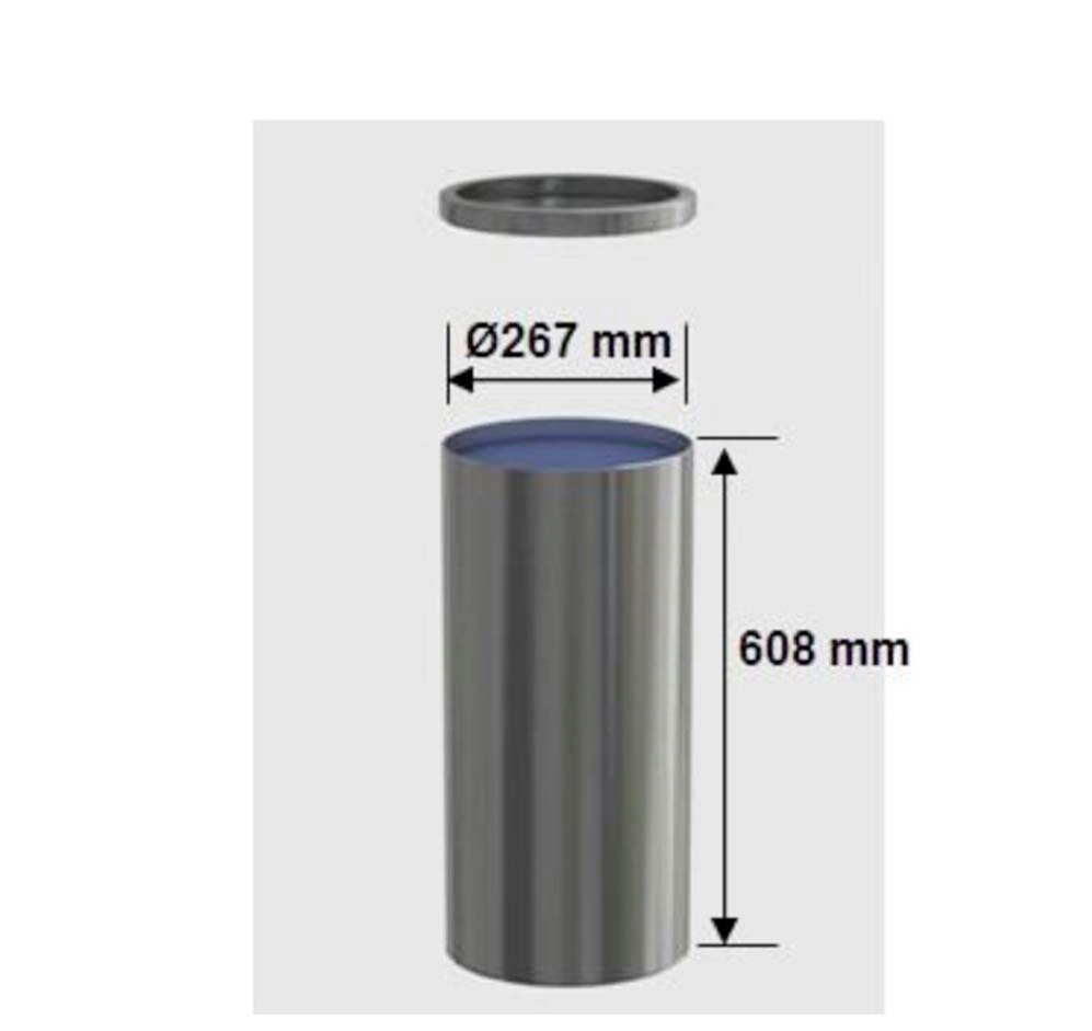
given in Table 11, the decay heat is around 21.2 W per waste block 40 years after the discharge of the reference PWR spent fuel. The storage canister shown in Fig. 10 is designed to accommodate two waste blocks. Thus, around 7 storage canisters are needed for the ceramic waste for the pyroprocess of 10 MtU of PWR spent fuel. The storage canister material is STS304L.
A disposal canister is designed with the specifications for waste blocks and storage canisters. The disposal
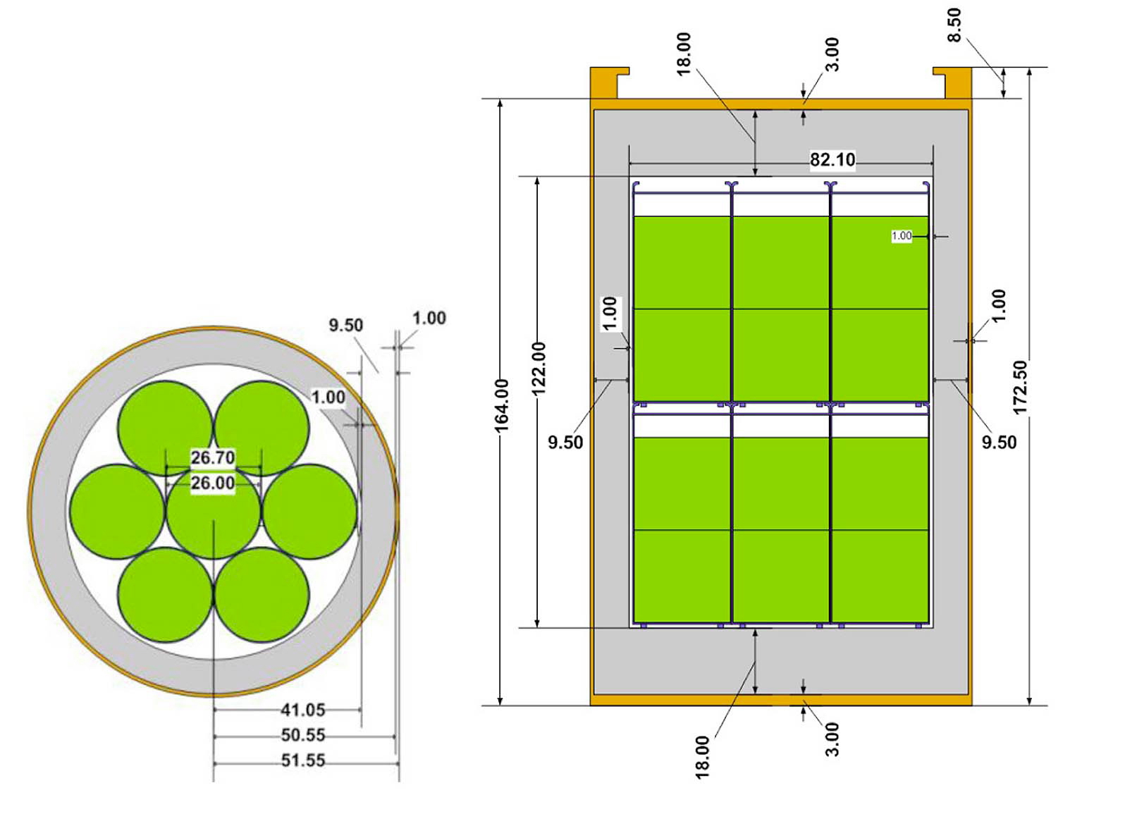
canister is a copper-nodular cast iron container. The lifetime of the copper shell is set to be 1,000 years. The thickness of the outer copper shell is 1.0 cm, as in an AKDC- CANDU canister, which will also be manufactured using a cold spray technique. According to a previous study [14], a 1.0 cm copper shell can persist for much longer than 1,000 years. The size of a disposal canister is designed in consideration of the decay heat and ease of handling. Fourteen storage canisters are stacked in one disposal canister, as shown in Fig. 11. Thus, the decay heat is around 600 W per disposal canister at the disposal moment, 40 years after the discharge.
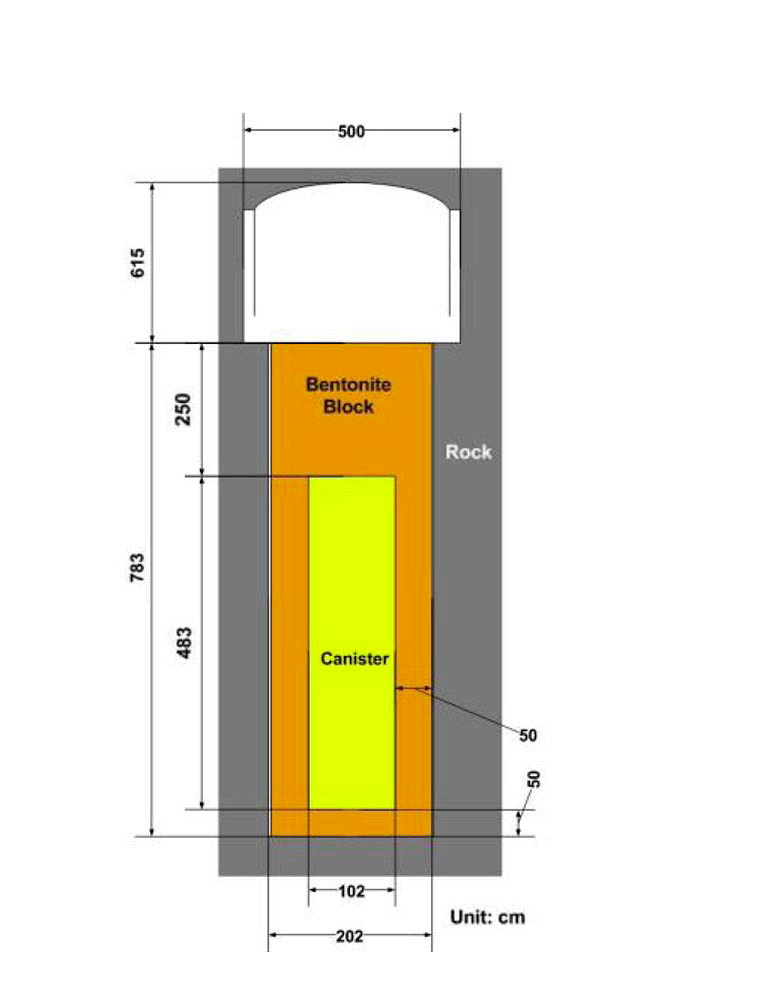
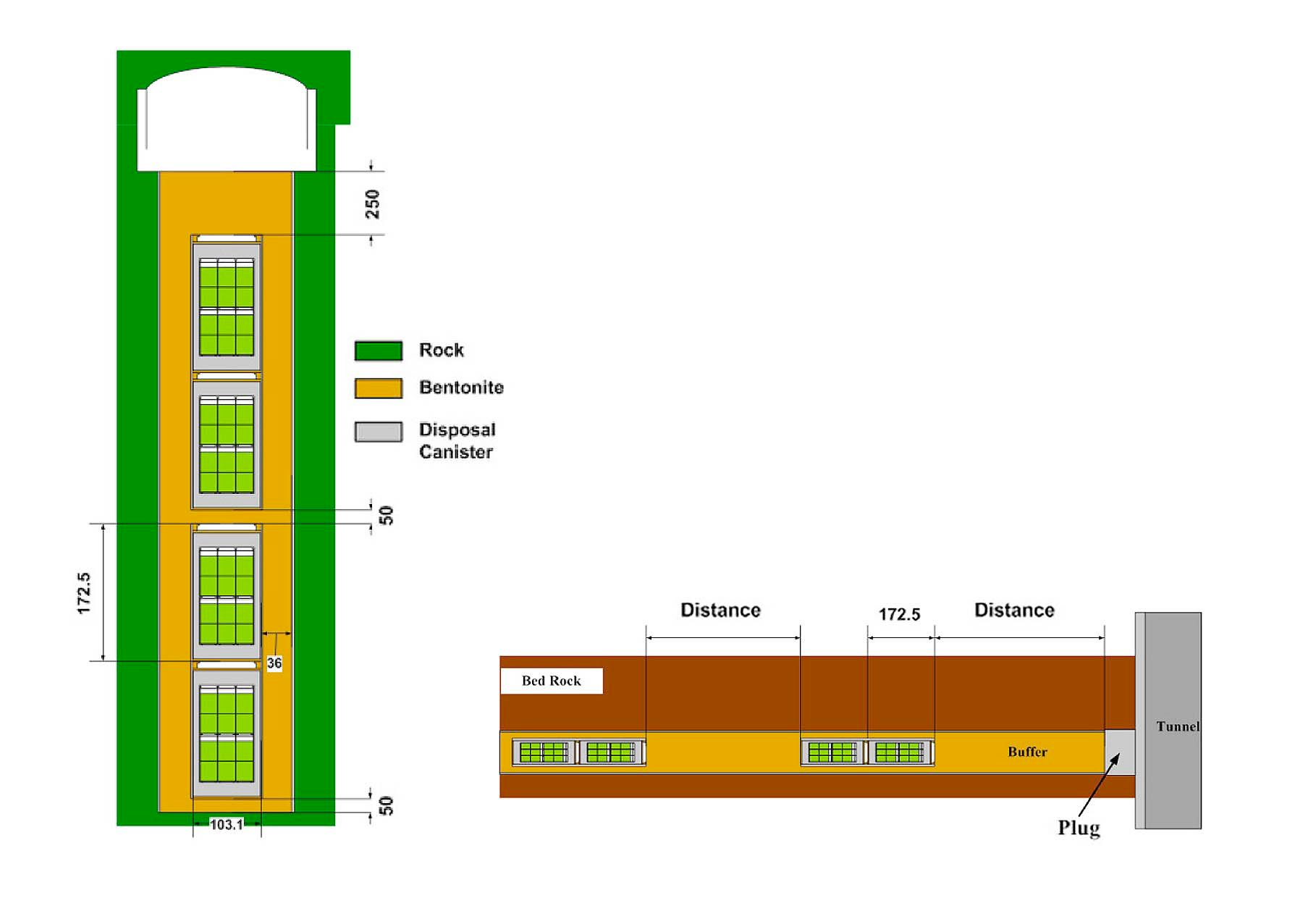
Two kinds of disposal methods are proposed and compared: one for a vertical deposition and the other for a horizontal deposition. Four disposal canisters are deployed in a vertical borehole as shown in Fig. 12. The domestic Ca-bentonite with a dry density of 1.6 g/cm3 is proposed as a buffer material. The distance between the deposition holes is determined through a thermal analysis. For the horizontal deployment, a horizontal tunnel with 32 disposal canisters is illustrated in Fig. 12.
4.2 Thermal Design of a Disposal System
According to the thermal analysis with the geological data from KURT [20], the distance between the boreholes for the vertical deposition of four disposal canisters is determined to be 8 m, not to exceed 100℃. Thus, the length of each tunnel is determined based on this distance. Also, the 5 % loss of boreholes due to fractures passing them is considered in determining the length. For the horizontal deposition, the distance between the disposal canisters is determined to be 2 m, for a tunnel spacing of 25 m, as given in Table 12. A comparison of the disposal areas between the pyroprocessing and direct disposal of spent
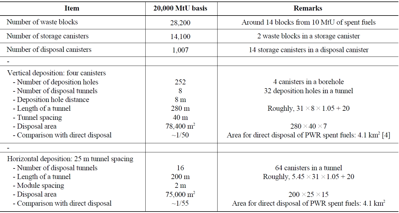
Comparison of the Disposal System for the Pyroprocess of 20,000 MtU of PWR Spent fuel [20]
fuel is also given in Table 12. The results show that the disposal area of the pyroprocessing reduces to around 1/50 of the direct disposal case.
Geological disposal systems have been developed to provide final solutions for the long-term management of spent fuel from nuclear power plants. The major features of geological disposal systems depend on the characteristics of the high-level waste and the geological system. The Korean Reference disposal System (KRS) was developed for the direct disposal of PWR and CANDU spent fuel. To provide more realistic geological data, a research tunnel, KURT, was constructed and supplied the data.
Taking into account the fissile material in CANDU spent fuel and the geological data from KURT, in this paper, the geological disposal system for CANDU spent fuel is improved to enhance the disposal density by introducing a new disposal canister, called A-KDCCANDU. With these new disposal canisters, the disposal density can be improved by 30%, and probable retrievability of the disposed canister is enhanced by reducing the weight of the canister, which helps in its handling.
A geological disposal system is proposed for highlevel waste from the pyroprocessing of spent fuel, based on geological data obtained from KURT. The amount and characteristics of high-level waste are analyzed based on the material balance of the pyroprocessing. The preliminary conceptual design of two disposal methods, one for vertical deposition and the other for horizontal deposition, is proposed for the thermal analysis. Through the thermal analysis, it was determined that the optimum distance between the vertical deposition holes with 4 overpacks is 8 m when the disposal tunnel spacing is 40 m, and an optimum distance of 2 m between the overpacks for a horizontal disposal tunnel with 25 m tunnel spacing. The ratio of disposal areas between the pyro-processing and direct disposal of spent fuel is around 1/50.

![Decay Heat from the Reference PWR Spent Fuel [7].](http://oak.go.kr/repository/journal/12576/OJRHBJ_2013_v45n1_29_f001.jpg)
![Amount of Spent Fuels used for the Design of KRS [1]](http://oak.go.kr/repository/journal/12576/OJRHBJ_2013_v45n1_29_t002.jpg)
![Characteristics of the Reference Spent Fuel for KRS [5]](http://oak.go.kr/repository/journal/12576/OJRHBJ_2013_v45n1_29_t003.jpg)
![Fracture Zone Classification and Repository Layout [1, 7]](http://oak.go.kr/repository/journal/12576/OJRHBJ_2013_v45n1_29_f002.jpg)
![Classification of the Fracture Zones [1, 7]](http://oak.go.kr/repository/journal/12576/OJRHBJ_2013_v45n1_29_t004.jpg)
![Schematic of a KDC-1 Canister (Left) and a KDC-CANDU Canister (Right) [7].](http://oak.go.kr/repository/journal/12576/OJRHBJ_2013_v45n1_29_f003.jpg)

![Design Requirements for a Buffer [7]](http://oak.go.kr/repository/journal/12576/OJRHBJ_2013_v45n1_29_t006.jpg)
![Schematic of a Buffer and Canister for Spent Fuels [7]](http://oak.go.kr/repository/journal/12576/OJRHBJ_2013_v45n1_29_f004.jpg)
![Schematic of the KRS Underground Disposal System [1, 7].](http://oak.go.kr/repository/journal/12576/OJRHBJ_2013_v45n1_29_f005.jpg)
![Number and Length of Disposal Tunnels [1, 7]](http://oak.go.kr/repository/journal/12576/OJRHBJ_2013_v45n1_29_t007.jpg)
![Schematic of an A-KDC-CANDU Canister and a Disposal System [13].](http://oak.go.kr/repository/journal/12576/OJRHBJ_2013_v45n1_29_f006.jpg)
![Comparison of Disposal Canisters [13]](http://oak.go.kr/repository/journal/12576/OJRHBJ_2013_v45n1_29_t008.jpg)
![Schematic of a Domain for the Thermal Analysis [14]](http://oak.go.kr/repository/journal/12576/OJRHBJ_2013_v45n1_29_f008.jpg)

![Characteristics of High-level Wastes from Pyroprocessing of 10 MtU PWR Spent Fuels [20]](http://oak.go.kr/repository/journal/12576/OJRHBJ_2013_v45n1_29_t010.jpg)
![Specifications of the Waste Block and Storage Canister [20]](http://oak.go.kr/repository/journal/12576/OJRHBJ_2013_v45n1_29_t011.jpg)
![Schematic of the Storage Canister [20].](http://oak.go.kr/repository/journal/12576/OJRHBJ_2013_v45n1_29_f010.jpg)
![Schematic of the Disposal Canister for Ceramic Wastes [20].](http://oak.go.kr/repository/journal/12576/OJRHBJ_2013_v45n1_29_f011.jpg)
![Schematic of the Disposal System, Vertical and Horizontal Depositions [20].](http://oak.go.kr/repository/journal/12576/OJRHBJ_2013_v45n1_29_f012.jpg)
![Comparison of the Disposal System for the Pyroprocess of 20,000 MtU of PWR Spent fuel [20]](http://oak.go.kr/repository/journal/12576/OJRHBJ_2013_v45n1_29_t012.jpg)