There are enormous asteroids formed at the beginning of the solar system. Most of them are rich in minerals, and some of them are dangerous to the Earth [1,2]. Thus, exploring the asteroids is of great significance, with the purpose of obtaining great economic effectiveness, and protecting the Earth. Landing on an asteroid is a great step towards exploring these asteroids, and its merits include: 1) learning about asteroids
Presently, most of the landing dynamic models are designed for lunar landing mechanisms, but are not suited to small body landing mechanisms, because of different landing environments, with different landing strategies [5-11]. The Europe Space Agency (ESA), National Aeronautics and Space Administration (NASA), and Japan Aerospace Exploration Agency (JAXA) have developed small body landing mechanisms, but the landing dynamic model is rarely used to evaluate the landing performance, and to guide the design of the landing mechanism [12-16]. They just evaluate the landing performance by simulation with the given value of the parameters, but don’t show how these values are educed [17].
In this paper, an Asteroid Landing and
2. The ALISE landing mechanism
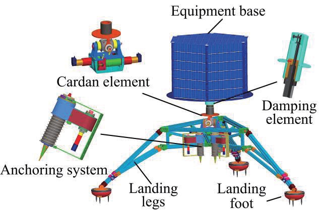
The ALISE landing mechanism aims at asteroids with soft surface(especially C type asteroid), which are softer than other asteroids, because of containing organic materials and amino acids [18,19], and the design is inspired by the Rosetta lander and the ST4/Champollion lander [20-22]. The ALISE landing mechanism includes a three-leg landing gear, and an anchoring system that is designed to avoid the flying away of the lander under low gravity. The landing gear contains landing foot, landing legs, cardan element, damping element, and equipment base. The damping element is realized by electromagnetic damping, which is a new technology in deep space exploration. This damping mode has the merits of high efficiency, easy control, adjustable damping, and so on, and has been used in the Rosetta landing mechanism [20]. The anchoring system contains anchoring element, propulsion element, rewinding element, and cushion element. The schematics and the performance parameters are shown
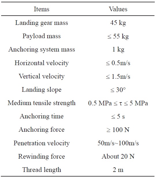
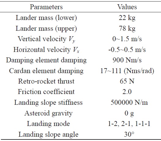
[Table 1.] Mechanical and landing performance parameters

Mechanical and landing performance parameters
separately in Fig. 1 and Table 1. Besides, the retro-rocket is fixed on the upper surface of the equipment base, to supply thrust towards the landing slope, to prevent the rebound of the landing mechanism, when landing. There is no sign of the retro-rocket in the schematics, because it is a part of the control system, but not a part of the mechanical structure.
There are awls beneath the landing feet to preventing sliding, and contact switches inside the landing feet, to generate landing signals. The cardan element has the functions of both absorbing the horizontal impact when landing, and adjusting the attitude of the equipment base after landing, while the damping element is just used to absorb the vertical impact. The anchoring element, which connects to the rewinding element via a thread, will be pushed rapidly into the asteroid by the propulsion element. At the time of penetration of the anchoring element, the rewinding element will quickly rewind the thread. When the thread is instantaneously tense, the cushion element, which is composed of a compression spring, will absorb the impact, to protect the rewinding motor. The retro-rocket will be activated at the time of landing, and supply a constant force lasting about 5 seconds toward the equipment base, to prevent the landing mechanism from rebounding.
The surface of the asteroid with soft surface is soft. When landing, the awls will penetrate the asteroid some depth, to prevent sliding of the landing mechanism, and the retrorocket would be activated, to counteract the rebound of the landing mechanism. Then, the landing mechanism will turn clockwise or counterclockwise around the feet’s anchoring points. The interaction between the awls and the surface is three-dimensional and very complicated, and few reasonable models can express this interaction accurately. Furthermore, the dynamic parameters in the first turning stage are enough to express the landing performance. Thus, the paper only develops the landing dynamic of the first turning stage. There are two-dimensional and three-dimensional landing dynamic models. But considering that the two-dimensional model is successfully adopted by the lunar lander, and that it is simpler than the three-dimensional model, a twodimensional landing dynamic is built for the ALISE landing mechanism.
Some hypotheses are made in building the landing dynamic model: 1) the gravity on the asteroid is of the order of magnitude about 10-4 m/s2, therefore the gravity is ignored; 2) the friction between the landing feet and landing legs is ignored; 3) The stiffness of the landing gear is far greater than that of the damping element vertically, and of the cardan element horizontally. So the flexibility of the landing gear is ignored; 4) the impulse acting on the landing mechanism when shooting the anchoring system is ignored; 5) the overturning of the landing mechanism is over, before the anchoring system tenses the thread.
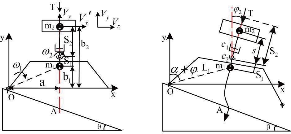
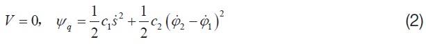
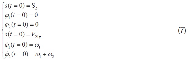
As shown in the right part of Fig. 2, the landing mechanism will turn around the point O when landing. The whole system has three degrees of freedom: rotational DOF of m1; rotational DOF of m2; and translational DOF of m2. The Lagrange equation is introduced, to buildng dynamic model. The kinetic energy
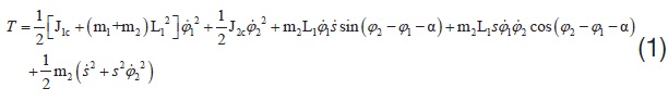
Then, the Lagrange dynamic equations are deduced, as shown in equations (3), (4) and (5).
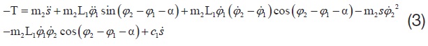
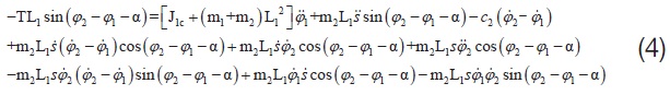

The parameters

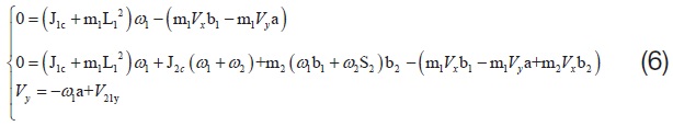
of landing dynamic characteristics can be solved by equations (3), (4) and (5) with the initial values. However, in a complicated landing impact, the initial values are difficult, or impossible to solve accurately - they can only be estimated. A schematic of the impact is shown in the left part of Fig. 2. Firstly, the impacting force acting on m1 at point O is far larger than the other external force, thus the impulse of m2 acting on m1 can be ignored. So the angular momentum of m1 around O is conservational. Secondly, ignoring the retro-rocket thrust T, the angular momentum of the system composed of m1 and m2 is conservational. Thirdly, there is a damping element between the m1 and m2 vertically, therefore the vertical velocity of the m2 changes continuously. Therefore the following equation (6) can be deduced. Meanings and values of the parameters in equation (6) are shown in Table 2.
where,
4. Estimations of the key parameters T, c1 and c2
From the landing dynamic model, as shown in equations (3), (4) and (5), it can be found that the landing performance parameters

are determined by
4.1 Estimation of retro-rocket thrust T
The retro-rocket supplies constant force T towards the upper surface of the equipment base, to prevent the landing mechanism from rebounding and overturning. In order to find the safe thrust, it is assumed that the landing mechanism is a rigid body, and its initial kinetic energy is
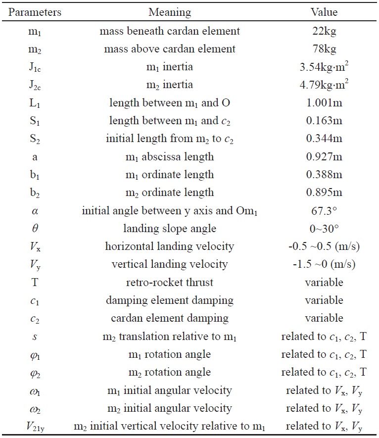
[Table 2.] 2 Meanings and values of the parameters

2 Meanings and values of the parameters
counteracted entirely by the retro-rocket thrust. There are counterclockwise overturning, and clockwise overturning. They need different values of thrust, to prevent overturning. Thus, it is necessary to estimate the thrust separately for the two types of overturning, and then the largest value is taken as the retro-rocket thrust value.
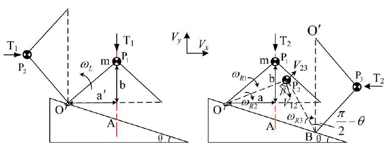
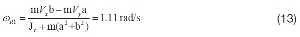
4.1.1 Counterclockwise overturning
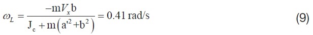
When landing with the initial velocity
The landing mechanism turns around the O point counterclockwise after impact, and the initial overturn angular velocity

The solution of equation (8) is:
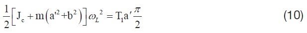
The largest allowable turning range of the landing mechanism without overturning is from P1 to P2. So the initial kinetic energy of the landing mechanism after impact should be counteracted totally by the retro-rocket thrust T1 during the angle ∠P1OP2, which equals π/2. Therefore, the following equation is obtained:
Obtaining:
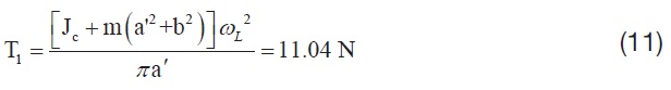
where, T1 is the retro-rocket thrust preventing the landing mechanism from counterclockwise overturning.
4.1.2 Clockwise overturning
When landing with the initial velocity
The landing mechanism turns around the O point clockwise after impact, and the initial turning angular velocity

Obtaining:
When the landing mechanism turns to the P2 position with the retro-rocket thrust T2, the angular velocity
be calculated by the energy conversion.
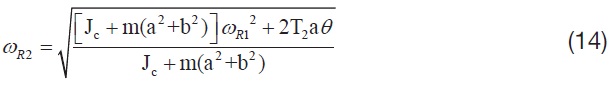
The tangential velocity of m in the P2 position is:

Then the landing mechanism will turn continuously around point B. It is assumed that the recovery coefficient

Then the initial angular velocity
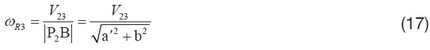
The largest allowable turning range of the landing mechanism, without overturning, is from P2 to P3. So the kinetic energy of the landing mechanism after P2 position should be counteracted totally by the retro-rocket T2 during the angle ∠P2BP3, which equals π/2-

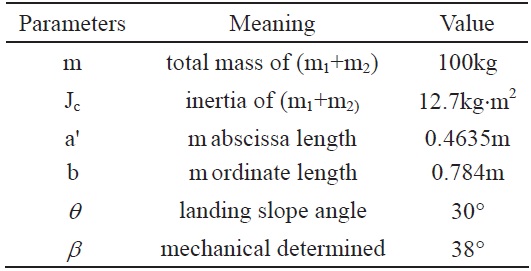
[Table 3.] Meanings and values of the parameters

Meanings and values of the parameters
Combining equations (13-18) yields the retro-rocket thrust T2 :
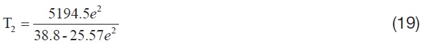
Substituting e with 0.6, we obtain:

The final retro-rocket thrust T should be no less than T1 or T2. In the paper, the retro-rocket thrust T is set to 65 N.
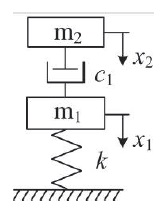
4.2 Estimation of the damping element damping c1
The dynamic model of the landing mechanism in the vertical direction could be simply expressed as Fig. 4 and equation (21), in which k is the stiffness of the landing mechanism.
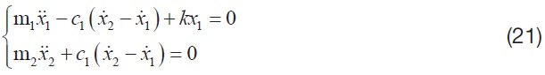
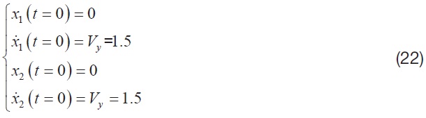
The initial conditions of equation (21) can be written as follows:
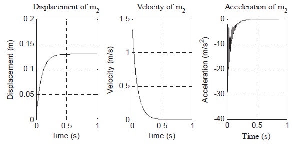
The overloading accelerations of m2 are different, on account of different
It can be found that the overloading acceleration of m2 is 30m/s2, and the stroke of the damping is 0.13m. These overloading acceleration and stroke are feasible for the landing mechanism. Thus, the parameters of the damping element are set to
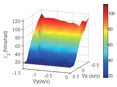
4.3 Calculation of cardan element damping c2
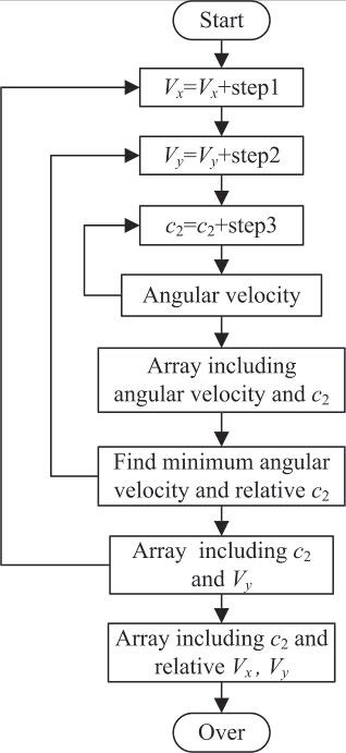
The
The value of
In the landing dynamic model, it can be found that during the turning,
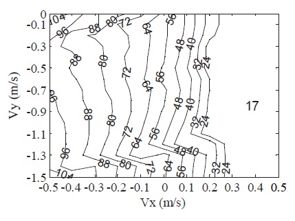
The values of
relationship shown in Fig. 7 or Fig. 8. The varying range of
The validities of the landing dynamic model and the parameters T,
5.1 Verification of the key parameters
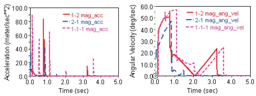
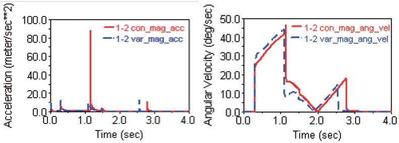
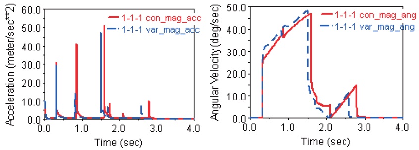
The landing performances in extreme landing conditions (
5.2 Influence of c2 on the landing performance
There are two modes of
[Table 4.] Simulation parameters

Simulation parameters
landing velocities), the other is optimal
which is shown in Fig. 7 and Fig. 8. The landing performance simulation results are shown in Fig. 10, Fig. 11 and Fig. 12, respectively, and the maximum overloading accelerations and stability times shown in these figures are summarized in Table 5. It can be found that both the maximum overloading accelerations and stability times with constant
A landing mechanism for asteroid with soft surface is presented. Reasonable values of the three key parameters (retro-rocket thrust T, damping element damping
In future, the landing mechanism will be manufactured, and then the validities of the landing mechanism and its parameters will be tested physically, under microgravity.
[Table 5.] Landing performances with constant and optimal c2 in three landing modes
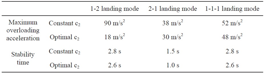
Landing performances with constant and optimal c2 in three landing modes